AIRCONDITIONINGCOMPRESSOR1-7
PressureReliefValve
Whena faultypressurereliefvalve,locatedintherear
headcasting,isencountered,thevalveassemblyshould
beremovedafterpurgingthesystemanda newvalveand
gasketinstalled.Theentiresystemshouldthenbe
evacuatedandrecharged.
CompressorRearHeadandInternalMechanism
Serviceoperationstotherearheadorinternalmech-
anismofthecompressorshouldbeperformedwiththe
compressorremovedfromthevehicletoinsurethatthe
necessarydegreeofcleanlinessmaybemaintained.
Cleanhandsanda cleanbench,preferablycoveredwith
cleanpaper,areofextremeimportance.
RearHead,OilPumpandValveAssemblies
Removal
1.
Removethecompressorfromthevehicle,drain
compressoroilintoa cleancontainer,cleanthe
exteriorofthecompressorcaseandrearheadcast-
ingwitha suitablesolventandmountthecompres-
sor,rearheadup,inholdingFixtureJ-9396which
shouldthenbemountedsecurelyina vise.
2.
Removethefournutsfromtheshellstuds.
3.
Removetherearhead.Examinetheteflonsurface
onthecastingwebs.Ifthissurfaceisdamagedby
nicksorscratches,theheadshouldbereplaced.
4.
Examinethesuctionscreenintherearheadforany
damageorcontamination.Cleanorreplacethe
screenasnecessary.
5.
Removeandexaminetheoilpumpgears.Ifeitherof
thegearsshowsanywearordamage,replaceboth
gears.
NOTE:Keeptheendsofthetwooilpumpgears
matchedandreplacethesameendtowardthe
dischargeplateuponreassembly.
6.Removetherearhead-to-shell"O"ringanddis-
card.
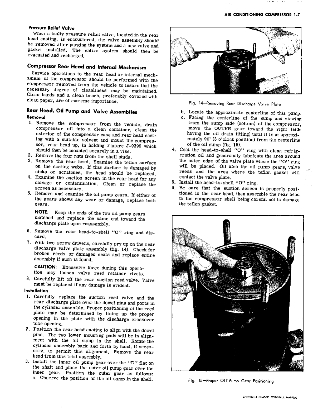
7.
Withtwoscrewdrivers,carefullypryupontherear
dischargevalveplateassembly(fig.14).Checkfor
brokenreedsordamagedseatsandreplaceentire
assemblyifsuchisfound.
CAUTION:Excessiveforceduringthisopera-
tionmayloosenvalvereedretainerrivets.
8.Carefullyliftofftherearsuctionreedvalve.Valve
mustbereplacedifanydamageisevident.
Installation
1.
Carefullyreplacethesuctionreedvalveandthe
reardischargeplateoverthedowelpinsandportsin
thecylinderassembly.Properpositioningofthereed
platemaybedeterminedbylininguptheproper
openingintheplatewiththedischargecrossover
tubeopening.
Positiontherearheadcastingtoalignwiththedowel
pins.
Thetwolowermountingpadswillbeinalign-
mentwiththeoilsumpintheshell.Rotatethe
cylinderassemblybackandforthbyhand,ifneces-
sary,topermitthisalignment.Removetherear
headfromthistrialassembly.
Installtheinneroilpumpgearoverthe"D"flaton
theshaftandplacetheouteroilpumpgearoverthe
innergear.Positiontheoutergearasfollows:
a.Observethepositionoftheoilsumpintheshell.
2.
3.
Fig.
14—RemovingRearDischargeValvePlate
5.
6.
b.
Locatetheapproximatecenterlineofthispump.
c.Facingthecenterlineofthesumpandviewing
fromthesumpside(bottom)ofthecompressor,
movetheOUTERgeartowardtheright(side
havingthe^oildrainfitting)untilitisatapproxi-
mately90°(3o'clockposition)fromthecenterline
oftheoilsump(fig.15).
Coatthehead-to-shell"O"ringwithcleanrefrig-
erationoilandgenerouslylubricatetheareaaround
theouteredgeofthevalveplatewherethe"O"ring
willbeplaced.Oilalsotheoilpumpgears,valve
reedsandtheareawheretheteflongasketwill
contactthevalveplate.
Installthehead-to-shell"O"ring.
Besurethatthesuctionscreenisproperlyposi-
tionedintherearhead,thenassembletherearhead
tothecompressorshellbeingcarefulnottodamage
theteflongasket.
Fig.
15—ProperOil"PumpGearPositioning
CHEVROLETCHASSISOVERHAULMANUAL