ChezRadio PROCASTER User manual

© 2020 Chezradio Inc.
PROCASTER
AM Transmitter Rev C
User Manual
March 2020
Before you start
Safety Warning
Never mount near electrical power lines! If the transmit-
ter falls down, it could contact the high voltage wires.
Safety Ground Warning
For the built-in lightning protection to work properly, the
Procaster grounding lug must be properly ground-
ed. Consult your local electrical safety standards.
Transmitter RF Ground
For maximum range, the Procaster grounding lug must
also be connected to a good RF (radio frequency)
ground. What makes a good electrical ground may be
a poor RF ground. A good RF ground will cause maxi-
mum current to flow in the antenna resulting in greater
radiation and best range.
IF YOU ARE NOT GETTING SUFFICIENT RANGE,
YOU MAY HAVE TO EXPERIMENT WITH DIFFER-
ENT RF GROUNDING – SEE THE GROUNDING
SECTION AT THE END OF THIS USER MANUAL!
Antes de empezar...
Advertencia de seguridad
¡Nunca monte cerca de las líneas eléctricas! Si el
transmisor se cae, podría ponerse en contacto con
los cables de alta tensión.
Advertencia de tierra de seguridad
Para que la protección contra rayos incorporada
funcione correctamente, la asa de puesta a tierra
Procaster debe estar correctamente conectada a
tierra. Consulte sus normas locales de seguridad
eléctrica.
Transmisor RF Ground
Para un rango máximo, la asa de puesta a tierra
Procaster también debe estar conectada a un buen
suelo de RF (radiofrecuencia). Lo que hace que un
buen suelo eléctrico puede ser un mal suelo de RF.
Un buen suelo de RF hará que la corriente máxima
fluya en la antena, lo que resulta en una mayor radi-
ación y mejor rango.
SI NO ESTÁ OBTENIENDO SUFICIENTE RANGO,
ES POSIBLE QUE TENGA QUE EXPERIMENTAR
CON DIFERENTES RF GROUNDING – VER LA
SECCIÓN DE PUESTA A TIERRA AL FINAL DE
ESTE MANUAL DE USUARIO!
© 2020 Chezradio Inc. 2
PROCASTER
AM Transmitter Rev C
User Manual
March 2020
Contents
• Procaster transmitter
• Studio interface
• 3-section antenna rods
• Power supply
• 4-conductor shielded cable (50ft or
100ft)
• U-bolts (2)
• Tuning tool
• Stainless hose clamps (2)
• Stainless lock nuts (2)
• User manual
Contenido
• Transmisor Procaster
• Interfaz de studio
• Barras de antena de 3 secciones
• Fuente de alimentación
• Cable blindado de 4 conductores (50 pies o
100 pies)
• Pernos en U (2)
• Herramienta de ajuste
• Abrazaderas de manguera inoxidable (2)
• Tuercas de fijación inoxidables (2)
• Manual de usuario
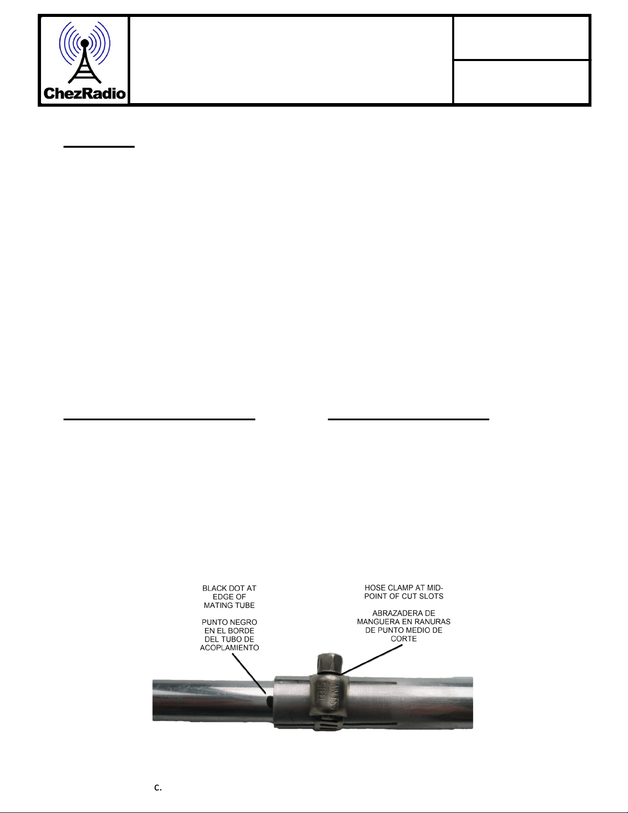
Assembling the Antenna
STEP 1
Assemble the 3 antenna sections by lining up
the black dot on one section with the edge of
the mating section. Each tube fits inside the
next larger size. Secure sections with the pro-
vided hose clamps at the mid-point of the cut
slots as shown below.
Montaje de la antena
PASO 1
Montar las 3 secciones de la antena alineando
el punto negro en una sección con el borde de
la sección de acoplamiento. Cada tubo cabe
dentro del siguiente tamaño más grande.
Asegure las secciones con las abrazaderas de
manguera proporcionadas en el punto medio de
las ranuras de corte, como se muestra a contin-
uación.

© 2020 Chezradio Inc. 3
PROCASTER
AM Transmitter Rev C
User Manual
March 2020
STEP 2
Remove the protective plastic shipping tubes
from the antenna mounting studs located on
the transmitter and discard them and attach the
antenna with the longest side pointing upwards
using the 2 nuts provided. The transmitter is
now ready for installation.
PASO 2
Retire los tubos de envío de plástico protectores de los
pernos de montaje de la antena situados en el transmisor
y deséchelos y conecte la antena con el lado más largo
apuntando hacia arriba utilizando las 2 tuercas propor-
cionadas. El transmisor ya está listo para su instalación.
Installation
STEP 3 MOUNTING LOCATION
Mount the transmitter vertically. The Procaster
comes with U-bolts that can accommodate up
to a 1-5/8in mast. The antenna must be in the
open away from items such as walls, fences,
masts, trees, power lines and other obstruc-
tions – see mounting methods below. For ex-
ample, a good location would be on the roof
of a 2-storey building at the end of a mast.
Note: you need to be able to reach the trans-
mitter for antenna tuning when in its final posi-
tion. You cannot tune the transmitter on the
ground and then raise it up.
Instalación
PASO 3 UBICACIÓN DE MONTAJE
Monte el transmisor verticalmente. El Procaster viene
con pernos en U que pueden acomodar hasta un mástil
de 1-5/8 pulgadas. La antena debe estar a la distancia
de elementos tales como paredes, cercas, mástiles,
árboles, líneas eléctricas y otras obstrucciones – ver
métodos de montaje a continuación. Por ejemplo, una
buena ubicación estaría en el techo de un edificio de 2
plantas al final de un mástil. Nota: usted necesita ser
capaz de alcanzar el transmisor para el ajuste de la
antena cuando está en su posición final. No se puede
afinar el transmisor en el suelo y luego subirlo.

© 2020 Chezradio Inc. 4
PROCASTER
AM Transmitter Rev C
User Manual
March 2020
Mast installation – correct installation of U-bolts
Instalación del mástil – correcta instalación de los pernos en U
STEP 4 CONNECT THE 4-CONDUCTOR CABLE
TO THE TRANSMITTER
The shielded cable has four conductors and a shield
(bare wire). Insert the cable into the bottom water-tight
bushing and connect to the green terminal block in-
side the transmitter as follows:
• Shield to SHLD (bare wire)
• RED to +12V
• BLACK to 0V
• GREEN to AUD-
WHITE to AUD+
Tighten the water-tight bushing (don’t over-tighten).
Use electrical tape where the wires exit from the
sheath to prevent accidental shorting to other compo-
nents inside the Procaster.
PASO 4 CONECTE EL CABLE DE 4 CONDUC-
TORES AL TRANSMISOR
El cable blindado tiene cuatro conductores y un escu-
do (cable desnudo). Inserte el cable en el casquillo
hermético inferior y conéctelo al bloque de terminales
verde dentro del transmisor de la siguiente manera:
• Escudo a SHLD (cable desnudo)
• ROJO a +12V
• NEGRO a 0V
• VERDE a AUD-
• BLANCO a AUD+
Apriete el casquillo hermético (no apriete demasiado).
Utilice cinta eléctrica donde los cables salgan de la
vaina para evitar cortocircuitos accidentales a otros
componentes dentro de la Procaster.
© 2020 Chezradio Inc. 5
PROCASTER
AM Transmitter Rev C
User Manual
March 2020
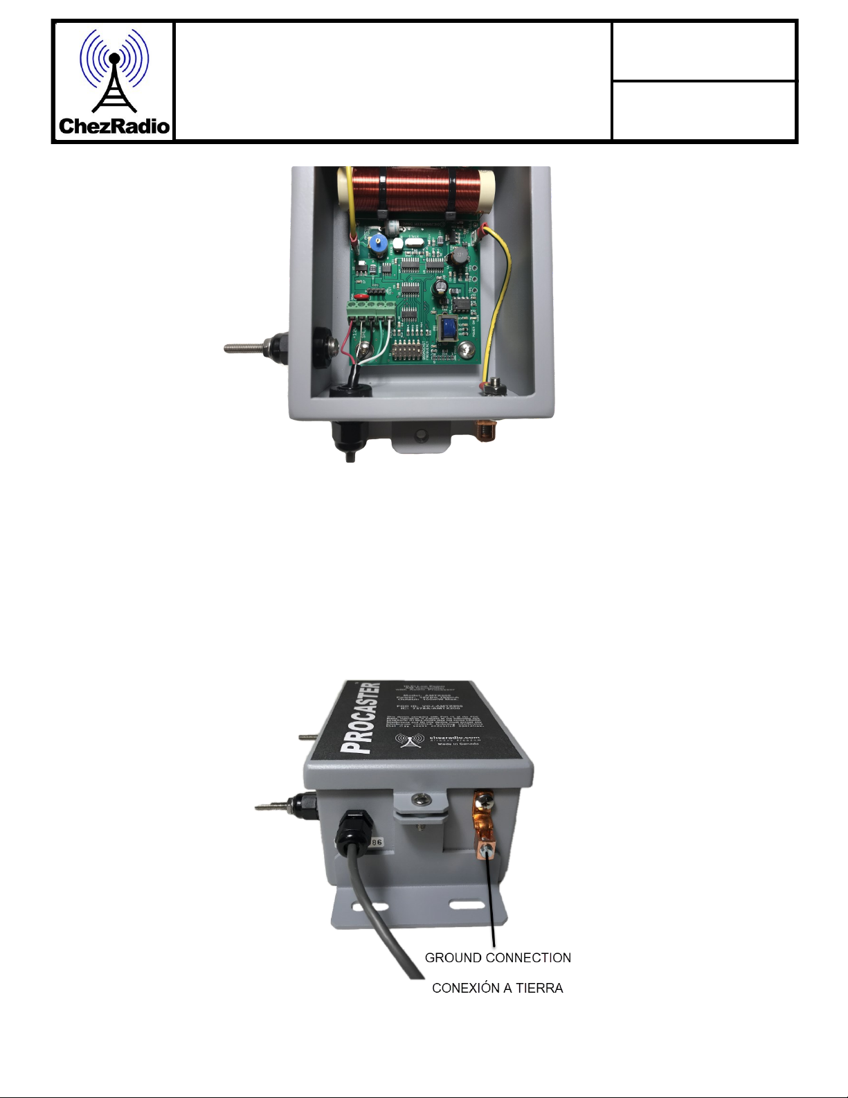
STEP 5 CONNECT THE GROUND LEAD
Connect a 12-gauge wire (recommended minimum
size) from the ground lug to a suitable ground (more
information on grounds is covered in the grounding
section). You can use an insulated 12-gauge wire
found at most hardware stores. The ground lead
should run as direct as possible to the ground.
PASO 5 CONECTE EL CABLE DE TIERRA
Conecte un cable de calibre 12 (tamaño mínimo
recomendado) desde la asa de tierra a un terreno
adecuado (más información sobre los terrenos se
cubre en la sección de puesta a tierra). Puede utiliz-
ar un cable aislado de calibre 12 que se encuentra
en la mayoría de las ferreterías. El cable de tierra
debe correr lo más directo posible al suelo.

© 2020 Chezradio Inc. 6
PROCASTER
AM Transmitter Rev C
User Manual
March 2020
STEP 6 CONNECT THE 4-CONDUCTOR CA-
BLE TO THE STUDIO INTERFACE
The Procaster connects to the studio interface
with the supplied 4 conductor shielded cable. Be-
cause the audio is balanced and the power con-
sumption is low, up to 250ft of 22-gauge shielded
wire (Belden 8723 or equivalent) can be used. Sys-
tem comes with 50ft standard – optional 100ft.
Bring the other end of the four-conductor shielded
cable inside the building. Add electrical tape to the
end of the cable to prevent shorting and keep the
wiring length similar as shown below. Connect to
the studio interface as follows:
RED to +12V
BLACK to 0V
GREEN to AUD-
WHITE to AUD+
Note: the shield is only connected at the trans-
mitter end. At the studio interface – simply cut
the shield off.
PASO 6 CONECTE EL CABLE DE 4 CONDUC-
TORES A LA INTERFAZ DE ESTUDIO
El Procaster se conecta a la interfaz del estudio con
el cable blindado de 4 conductores suministrado.
Debido a que el audio está equilibrado y el consumo
de energía es bajo, se puede utilizar hasta 250 pies
de cable blindado de calibre 22 (Belden 8723 o
equivalente). El sistema viene con estándar de 50
pies : opcional de 100 pies.
Lleve el otro extremo del cable blindado de cuatro
conductores dentro del edificio. Agregue cinta eléc-
trica al extremo del cable para evitar el cortocircuito
y mantener la longitud del cableado similar como se
muestra a continuación. Conéctese a la interfaz del
estudio de la siguiente manera:
ROJO a +12V
NEGRO a 0V
VERDE a AUD-
BLANCO a AUD+
Nota: el escudo sólo está conectado en el ex-
tremo del transmisor. En la interfaz del estudio,
simplemente corte el escudo.
© 2020 Chezradio Inc. 7
PROCASTER
AM Transmitter Rev C
User Manual
March 2020
STEP 7 CHOOSING YOUR BROADCAST FRE-
QUENCY
Drive around your chosen broadcast area and listen
for clear channels. Note: car radios are usually more
sensitive than portables (range also depends on the
quality of the receiver). If you want to broadcast at
night, you will have to check if the channel is clear
then. It's more difficult to broadcast at night be-
cause sky-waves from higher-powered radio sta-
tions reach into your broadcast area and will reduce
your effective transmit range; so, bear that in mind.
PASO 7 ELEGIR SU FRECUENCIA DE TRANS-
MISIÓN
Conduzca alrededor de su área de transmisión ele-
gida y escuche canales claros. Nota: las radios de
los coches son generalmente más sensibles que los
portátiles (el rango también depende de la calidad
del receptor). Si desea transmitir por la noche,
tendrá que comprobar si el canal está claro entonc-
es. Es más difícil de transmitir por la noche porque
las ondas del cielo de las estaciones de radio de
mayor potencia llegan a su área de transmisión y
reducirán su rango de transmisión efectivo; así que,
tenlo en cuenta.
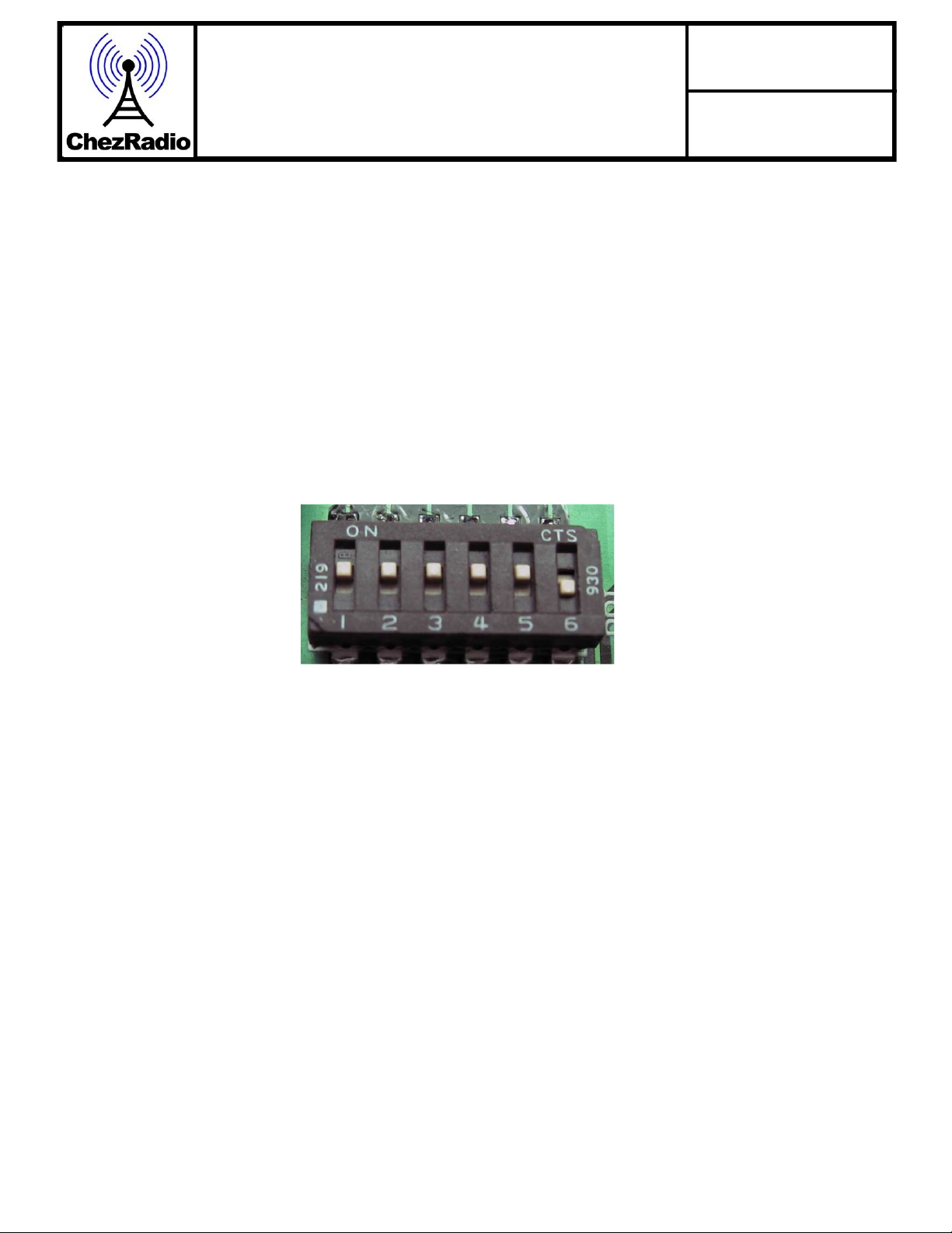
1610kHz shown
1610kHz mostrado
Determine the highest clear frequency available
in your area and select one of the 42 channels
available using the ‘Broadcast Frequency’
switches. Because of the short restrictive an-
tenna length mandated by the authorities, you
will get the best range by choosing the highest
frequency (shown in the shaded section).
Determine la frecuencia clara más alta dis-
ponible en su área y seleccione uno de los 42
canales disponibles utilizando los interruptores
'Frecuencia de difusión'. Debido a la corta lon-
gitud restrictiva de la antena exigida por las
autoridades, obtendrá el mejor rango eligiendo
la frecuencia más alta (que se muestra en la
sección sombreada).

© 2020 Chezradio Inc. 8
PROCASTER
AM Transmitter Rev C
User Manual
March 2020
Broadcast Frequency Settings
Ajustes de frecuencia de difusión
Freq
kHz S1 S2 S3 S4 S5 S6
1290 ON ON ON ON ON ON
1300 OFF ON ON ON ON ON
1310 ON OFF ON ON ON ON
1320 OFF OFF ON ON ON ON
1330 ON ON OFF ON ON ON
1340 OFF ON OFF ON ON ON
1350 ON OFF OFF ON ON ON
1360 OFF OFF OFF ON ON ON
1370 ON ON ON OFF ON ON
1380 OFF ON ON OFF ON ON
1390 ON OFF ON OFF ON ON
1400 OFF OFF ON OFF ON ON
1410 ON ON OFF OFF ON ON
1420 OFF ON OFF OFF ON ON
1430 ON OFF OFF OFF ON ON
1440 OFF OFF OFF OFF ON ON
1450 ON ON ON ON OFF ON
1460 OFF ON ON ON OFF ON
1470 ON OFF ON ON OFF ON
1480 OFF OFF ON ON OFF ON
1490 ON ON OFF ON OFF ON
1500 OFF ON OFF ON OFF ON
1510 ON OFF OFF ON OFF ON
1520 OFF OFF OFF ON OFF ON
1530 ON ON ON OFF OFF ON
1540 OFF ON ON OFF OFF ON
1550 ON OFF ON OFF OFF ON
1560 OFF OFF ON OFF OFF ON
1570 ON ON OFF OFF OFF ON
1580 OFF ON OFF OFF OFF ON
1590 ON OFF OFF OFF OFF ON

© 2020 Chezradio Inc. 9
PROCASTER
AM Transmitter Rev C
User Manual
March 2020
Best Range Frequency Settings
Mejor conguración de frecuencia de rango
Freq
kHz S1 S2 S3 S4 S5 S6
1600 OFF OFF OFF OFF OFF ON
1610 ON ON ON ON ON OFF
1620 OFF ON ON ON ON OFF
1630 ON OFF ON ON ON OFF
1640 OFF OFF ON ON ON OFF
1650 ON ON OFF ON ON OFF
1660 OFF ON OFF ON ON OFF
1670 ON OFF OFF ON ON OFF
1680 OFF OFF OFF ON ON OFF
1690 ON ON ON OFF ON OFF
1700 OFF ON ON OFF ON OFF
1710* ON OFF ON OFF ON OFF
* outside the AM band but most receivers
can tune to this frequency – this is usually a
quiet spot (band officially ends at upper side
band limit of 1705kHz)
* fuera de la banda AM, pero la mayoría de los
receptores pueden sintonizar esta frecuencia –
esto es generalmente un punto tranquilo (la
banda termina oficialmente en el límite de la
banda lateral superior de 1705 kHz)
Initial power on and antenna
tuning
STEP 8 POWER UP
The Procaster is designed to be powered from
12VDC and consumes approximately 100mA. The
output of the power supply supplied is about 15VDC
with the transmitter system connected. This higher
voltage is required to compensate for the voltage
loss in up to 250ft (maximum permitted) of connect-
ing cable.
For remote locations with no power available, the
entire system can easily be run from a 12V battery
charged by a solar panel. If the power source is
fixed at around 12VDC, then the connecting cable
needs to be shorter to make sure that voltage drop
in the wiring does not go below 12VDC at the trans-
mitter otherwise transmit power will be reduced.
Encendido inicial y sin-
tonización de antena
STEP 8 POWER UP
El Procaster está diseñado para ser alimentado
desde 12VDC y consume aproximadamente
100mA. La salida de la fuente de alimentación su-
ministrada es de aproximadamente 15VDC con el
sistema transmisor conectado. Esta tensión más
alta es necesaria para compensar la pérdida de
tensión en hasta 250 pies (máximo permitido) del
cable de conexión.
Para ubicaciones remotas sin alimentación dis-
ponible, todo el sistema se puede ejecutar fácilmen-
te desde una batería de 12V cargada por un panel
solar. Si la fuente de alimentación se fija en al-
rededor de 12VDC, entonces el cable de conexión
debe ser más corto para asegurarse de que la caída
de tensión en el cableado no vaya por debajo de
12VDC en el transmisor de lo contrario se reducirá
la potencia de transmisión.
© 2020 Chezradio Inc. 10
PROCASTER
AM Transmitter Rev C
User Manual
March 2020
STEP 9 ANTENNA TUNING
Go outside to the transmitter and place the re-
cessed end of the tuning tool over the brass slotted
screw of the antenna tuning capacitor a (this is the
yellow or blue circular component labeled C18 near
the yellow antenna wire) and turn in either direction
until a maximum reading is seen on the tuning me-
ter. Stand away from the antenna when tuning
as your body will affect the results.
Do not adjust the METER TRIMMER POTENTI-
OMETER! – this is only adjusted if the meter reads
fully to the right off-scale – in this case you will not
be able to see a maximum. The only purpose of the
tuning meter is to indicate a MAXIMUM – the num-
bers are not important.
Failing to tune the antenna tuning capacitor
properly is the leading cause of poor range! The
antenna must be tuned after the Procaster is
installed in its final position – you cannot tune
the antenna and then raise up the Procaster!
The carrier fine frequency is adjusted at time of
manufacture to ensure that the carrier is as accu-
rate as possible and does not need adjusting.
The only time this trimmer may have to be adjusted
is when the Procaster is near another Procaster on
the same frequency. When the frequencies are very
close, adjust the trimmer of one Procaster such that
the resulting ‘beating’ will becomes as slow as pos-
sible.
This trimmer can be adjusted using a small jewelers
flat-bladed screwdriver and it turns continuously.
Phase differences in the carriers cannot be adjust-
ed.
PASO 9 AJUSTE DE LA ANTENA
Salga al transmisor y coloque el extremo empotra-
ble de la herramienta de ajuste sobre el tornillo
ranurado de latón del condensador de ajuste de la
antena a (este es el componente circular amarillo o
azul etiquetado C18 cerca del cable de la antena
amarillo) y gire en cualquier dirección hasta un
máximo lectura se ve en el medidor de afinación.
Alétate de la antena cuando afinas, ya que tu
cuerpo afectará los resultados.
¡No ajuste el POTENCIÓMETRO DE RECORTA-
DOR DE MEDIDOR! – esto sólo se ajusta si el me-
didor se lee completamente a la derecha fuera de
escala - en este caso usted no será capaz de ver
un máximo. El único propósito del medidor de afi-
nación es indicar un MAXIMUM – los números no
son importantes.
¡No ajustar el condensador de ajuste de antena
correctamente es la causa principal de un rango
deficiente! La antena debe ser sintonizada
después de que el Procaster se instala en su
posición final - no se puede afinar la antena y
luego levantar el Procaster!
La recortadora de afinación fina del portador se
ajusta en el momento de la fabricación para
asegurarse de que el portador es lo más preciso
posible y no necesita ajuste.
La única vez que esta recortadora puede tener que
ser ajustada es cuando el Procaster está cerca de
otro Procaster en la misma frecuencia. Cuando las
frecuencias estén muy cerca, ajuste la recortadora
de un Procaster de modo que la "paliza" resultante
se vuelva lo más lenta posible.
Esta recortadora se puede ajustar con un pequeño
destornillador de hoja plana joyeros y gira continua-
mente. Las diferencias de fase en los portadores
no se pueden ajustar.

© 2020 Chezradio Inc. 11
PROCASTER
AM Transmitter Rev C
User Manual
March 2020
STEP 10 ATTACH TRANSMITTER COVER
Close up the Procaster. Tighten the 2 cover
screws evenly – don’t over-tighten!
PASO 10 FIJAR LA CUBIERTA DEL TRANSMISOR
Cierra el Procaster. Apriete los 2 tornillos de la cubierta uni-
formemente - ¡no apriete demasiado!
STEP 11 CONNECT AUDIO
The Procaster is fitted with a universal
3.5mm input jack. It has been designed to
accept stereo left and right audio channels
and mix them into a mono signal. If you only
have a mono signal, you can apply it to ei-
ther the left or the right input connection.
The built-in audio processor has a fairly
wide accommodation range and will auto-
matically adjust audio level for optimum
sound quality. If you use an external audio
processor you can turn off the built-in audio
processor by moving the jumper to the ‘off’
position. In addition, there is an input audio
level adjustment control (normally set at mid
-point) accessible through the studio inter-
face front panel.
STEP 11 CONECTAR AUDIO
El Procaster está equipado con un conector de entrada
universal de 3,5 mm. Ha sido diseñado para aceptar
canales de audio estéreo izquierdo y derecho y mezclar-
los en una señal mono. Si solo tiene una señal mono,
puede aplicarla a la conexión de entrada izquierda o
derecha.
El procesador de audio incorporado tiene un rango de
alojamiento bastante amplio y ajustará automáticamente
el nivel de audio para una calidad de sonido óptima. Si
utiliza un procesador de audio externo, puede apagar el
procesador de audio integrado moviendo el puente a la
posición de apagado. Además, hay un control de ajuste
de nivel de audio de entrada (normalmente establecido
en el punto medio) accesible a través del panel frontal
de la interfaz del estudio.

© 2020 Chezradio Inc. 12
PROCASTER
AM Transmitter Rev C
User Manual
March 2020
STEP 12 STUDIO INTERFACE ADJUSTMENTS PASO 12 AJUSTES DE LA INTERFAZ DE ESTUDIO
There are various adjustments within the studio
interface as follows:
Input Gain Adjust
Turning CW increases sensitivity for line level in-
puts.
Audio Processor on/off
The internal audio processor can be bypassed
when an external audio processor is used.
Compression adjustment
Compression boosts quieter parts of the audio to
be more equal to the louder parts. This makes the
overall audio louder resulting in a stronger signal
and greater range. The tradeoff is the subjective
audio quality depending on the level of compres-
sion. Settings are 1:1, 2:1, 5:1 and 10:1. Default is
2:1.
1:1
2:1 (default)
5:1
10:1
Hay varios ajustes dentro de la interfaz del
estudio de la siguiente manera:
Ajuste de ganancia de entrada
Girar CW aumenta la sensibilidad para las
entradas de nivel de línea.
Procesador de audio activado/desactivado
El procesador de audio interno se puede
omitir cuando se utiliza un procesador de au-
dio externo.
Ajuste de compresión
La compresión aumenta las partes más si-
lenciosas del audio para que sean más
iguales a las partes más ruidosas. Esto hace
que el audio general sea más fuerte, lo que
resulta en una señal más fuerte y un mayor
alcance. La contrapartida es la calidad de au-
dio subjetiva dependiendo del nivel de com-
presión. Los ajustes son 1:1, 2:1, 5:1 y 10:1.
El valor predeterminado es 2:1.
1:1
2:1 (predeterminado)
5:1
10:1

© 2020 Chezradio Inc. 13
PROCASTER
AM Transmitter Rev C
User Manual
March 2020
Modulation depth
This is only active when the internal audio pro-
cessor is used. Turning the modulation depth
control CW increases the audio modulation
level of the AM signal. Some additional over
modulation (depending on your application)
adds 'punch' to the received audio resulting in
a stronger, louder signal and greater range.
Default is midway.
Input Isolation
Sometimes the building ground voltage is dif-
ferent from earth ground resulting in an audible
hum in the receiver. In the DIR position, the
source equipment ground is connected to the
Procaster ground. In the ISOL position the sig-
nal is isolated from the Procaster ground via a
transformer. This eliminates the hum, but low
frequency response may be reduced some-
what. Only use ISOL if hum is present to en-
sure best low frequency response.
Limiting
Limiting is automatic to prevent sideband
'splatter' and is always active when the internal
audio processor is being used.
Profundidad de modulación
Esto sólo está activo cuando se utiliza el procesador
de audio interno. Al girar el control de profundidad de
modulación CW aumenta el nivel de modulación de
audio de la señal AM. Algunas modulaciones adicion-
ales (dependiendo de su aplicación) añaden
"puñetazo" al audio recibido, lo que resulta en una
señal más fuerte, más fuerte y mayor alcance. El val-
or predeterminado es a mitad de camino.
Aislamiento de entrada
A veces la tensión de tierra del edificio es diferente
de la tierra, lo que resulta en un zumbido audible en
el receptor. En la posición DIR, el suelo del equipo
de origen está conectado al suelo de Procaster. En la
posición ISOL la señal se aísla del suelo Procaster a
través de un transformador. Esto elimina el zumbido,
pero la respuesta de baja frecuencia puede reducirse
un poco. Utilice solamente ISOL si el zumbido está
presente para asegurar la mejor respuesta de baja
frecuencia.
Limitar
La limitación es automática para evitar la
"salpicadura" de banda lateral y siempre está activa
cuando se utiliza el procesador de audio interno.
STEP 13 CONNECTING TO GROUND
AM transmitters are ground-based systems
and need a good ground for optimum range
and signal strength as well as protection from
lightning. Lightning will usually take the easiest
path to ground thus preventing accidental entry
into the home.
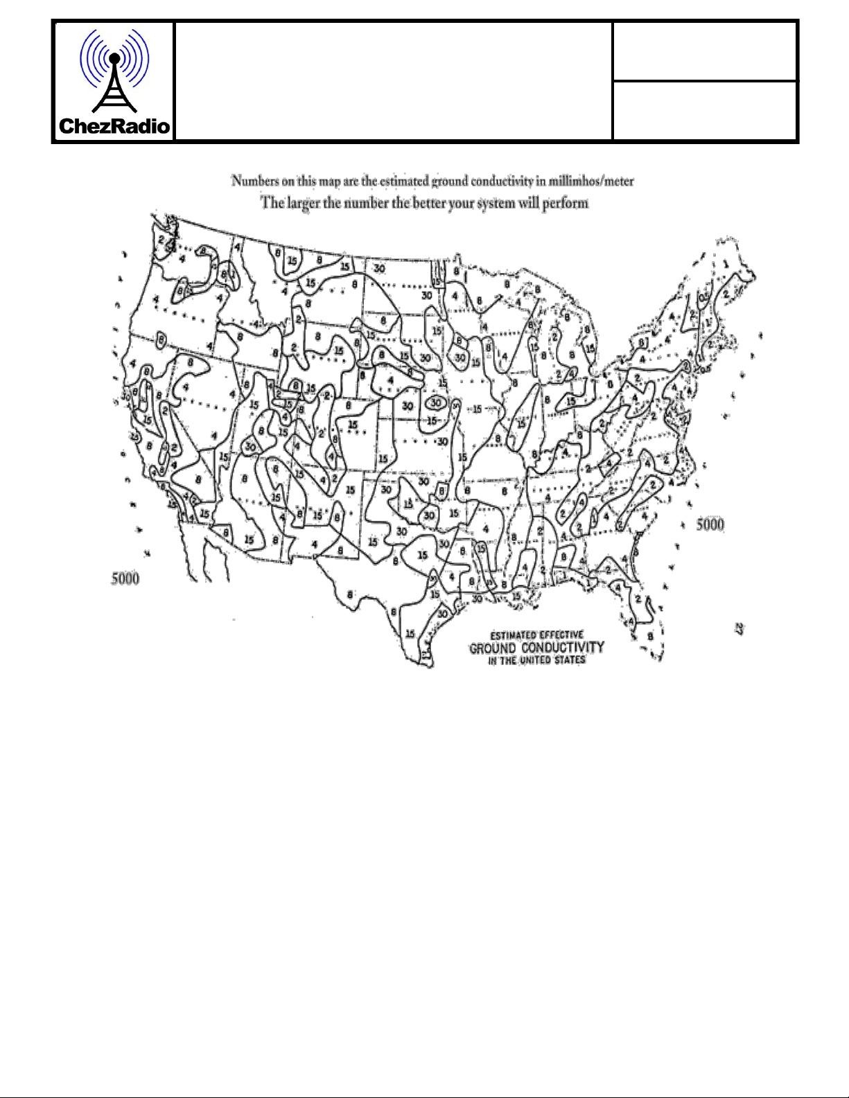
Ground conductivity varies with geographical
location as shown in this US ground map be-
low. If you are unfortunate to be in a poor con-
ductivity area, you may need to enhance your
ground system such as adding sodium benton-
ite into the earth where the ground rods are
located. Sand and gravel even when wet, often
result in poor grounds. Saltwater marshes are
best.
Performance is also dictated by your range
requirement – if your range is not required to
be very far (for example, a truck depot), the
quality of your grounding is not as important,
but you still have to be vigilant concerning light-
ning.
PASO 13 CONEXIÓN A TIERRA
Los transmisores AM son sistemas basados en tier-
ra y necesitan un buen terreno para un rango y po-
tencia de señal óptimos, así como protección contra
rayos. Los rayos generalmente toman el camino
más fácil al suelo evitando así la entrada accidental
en el hogar.
La conductividad del suelo varía con la ubicación
geográfica como se muestra en este mapa terrestre
de EE. UU. a continuación. Si usted es desafortuna-
do de estar en un área de conductividad pobre, es
posible que tenga que mejorar su sistema de tierra,
como la adición de bentonita de sodio en la tierra
donde se encuentran las varillas de tierra. Arena y
grava incluso cuando está mojado, a menudo re-
sultan en terrenos pobres. Las marismas de agua
salada son las mejores.
El rendimiento también está dictado por su requisito
de alcance - si su gama no está obligada a estar
muy lejos (por ejemplo, un depósito de camiones),
la calidad de su puesta a tierra no es tan im-
portante, pero todavía tiene que estar atento a los
rayos.
© 2020 Chezradio Inc. 14
PROCASTER
AM Transmitter Rev C
User Manual
March 2020
There are several methods of grounding the Pro-
caster. We recommend using a ground rod as the
most straightforward method.
Ground rod
The simplest and most popular method is to use a
5/8in x 8ft ground rod (steel core surrounded by
copper) driven into the ground full length. Several
ground rods spaced 6ft apart and joined together
can further reduce the resistance to ground. Keep-
ing the ground moist by locating rods near an air
conditioner drip point or run-off from a roof down-
spout can also reduce overall ground resistance.
The following parts may be obtained from your
local hardware store:
Hay varios métodos para atierrar el Procaster.
Recomendamos utilizar una varilla de tierra como
el método más sencillo.
Barra de tierra
El método más simple y popular es utilizar una
varilla de tierra de 5/8" x 8 ft (núcleo de acero
rodeado de cobre) accionada en toda la longitud
del suelo. Varias varillas de tierra separadas a 6
pies y unidas pueden reducir aún más la resisten-
cia al suelo. Mantener el suelo húmedo localizan-
do varillas cerca de un punto de goteo del aire
acondicionado o escorrente desde un techo hacia
abajo también puede reducir la resistencia general
al suelo. Las siguientes piezas se pueden obtener
de su ferretería local:

© 2020 Chezradio Inc. 15
PROCASTER
AM Transmitter Rev C
User Manual
March 2020
5/8in x 8ft copper clad steel ground rod
5/8in x 8ft de cobre relado de acero atraviado varilla de
5/8in bronze clamp
Abrazadera de bronce de 5/8
#6-gauge 7 strand copper wire
#6 calibre de 7 hilos de alambre de cobre
#12-gauge plastic covered copper wire
alambre de cobre recubierto de plástico de calibre
If you need to connect several ground rods to-
gether, simply continue the wire through the
clamp and onto the next rod and clamp and so
on. Smear clamp with automotive grease to re-
duce corrosive effects.
If your ground is hard or has clay, you can use
the water drill method instead of pounding with a
sledgehammer. This method uses a hollow tube
(copper preferably) with a hose attached at one
end. The flowing water washes away earth and
allows the tube to penetrate into the ground.
There are several examples on YouTube ex-
plaining how to do this.
Si necesita conectar varias varillas de tierra jun-
tas, simplemente continúe el cable a través de la
abrazadera y en la siguiente varilla y abrazadera
y así sucesivamente. Abrazadera de frotis con
grasa automotriz para reducir los efectos corro-
sivos.
Si su tierra es dura o tiene arcilla, puede utilizar
el método de perforación de agua en lugar de
golpear con un mazo. Este método utiliza un
tubo hueco (cobre preferiblemente) con una
manguera conectada en un extremo. El agua
que fluye lava la tierra y permite que el tubo pen-
etre en el suelo. Hay varios ejemplos en
YouTube que explican cómo hacerlo.
Run the copper wire down from the Procaster
as straight and directly as possible to the
ground rod trying to avoid sharp turns. Attach
ground wire using a 5/8in bronze clamp as
shown below:
Ejecute el cable de cobre desde la Procaster
tan recto y directamente como sea posible a
la varilla de tierra tratando de evitar giros
bruscos. Fije el cable de tierra con una abra-
zadera de bronce de 5/8" como se muestra a
continuación:

© 2020 Chezradio Inc. 16
PROCASTER
AM Transmitter Rev C
User Manual
March 2020
Other grounding methods include (more infor-
mation can be found online)
Radial ground system
The Procaster should be positioned in the centre of
the radial pattern and the ground radials should be as
long as your antenna is high (examples online).
Metal roof
A metal roof can provide an effective elevated ground
system if the metal panels are electrically connected
to one another. The Procaster can be mast-mounted
on a tripod which is attached to the roof with bolts or
is held in position with concrete blocks. The ad-
vantage of the elevated ground system is that the
transmitter is higher and more likely to have better
range. Connect to the ground lug of the Procaster with
a 12-gauge or thicker copper wire.
Underground metal water pipes
(CAUTION – lightning could enter building using
this method)
Electrical panels usually ground to the copper water
pipe very near to where it comes out from the ground
inside the building. It is unknown how well these pipes
are connected electrically, and the electrical system
may induce noise into the Procaster which will be
heard on the receiving radio. Connect to the ground
lug of the Procaster with 12-gauge or thicker copper
wire.
Building electrical ground
(CAUTION – lightning could enter building using
this method)
Building electrical grounds can work quite well, but
there is the risk of electrical noise from household ap-
pliances getting picked up by the Procaster and trans-
mitted to the receiving radio. This is something you
have to try out and see - all situations are different.
Connect to the ground lug of the Procaster with a 12-
gauge or thicker copper wire.
STEP 14 FINAL CHECKOUT
Check your sound level and range by listening on a
radio. The broadcast signal should be clear and
strong when closer to the transmitter, with more noise
heard the further you move away.
Otros métodos de puesta a tierra incluyen (más in-
formación se puede encontrar en línea)
Sistema de tierra radial
El Procaster debe colocarse en el centro del patrón
radial y los radiales de tierra deben ser siempre y cuan-
do su antena sea alta (ejemplos en línea).
Techo metálico
Un techo de metal puede proporcionar un sistema de
tierra elevado eficaz si los paneles metálicos están
conectados eléctricamente entre sí. El Procaster se
puede montar en un trípode que está unido al techo
con pernos o se mantiene en posición con bloques de
hormigón. La ventaja del sistema de tierra elevado es
que el transmisor es más alto y más propenso a tener
un mejor alcance. Conéctese a la asa de tierra del Pro-
caster con un cable de cobre de calibre 12 o más grue-
so.
Tuberías subterráneas de agua metálica
(CAUTION – un rayo podría entrar en el edificio
usando este método)
Los paneles eléctricos generalmente se atierran a la
tubería de agua de cobre muy cerca de donde sale del
suelo dentro del edificio. Se desconoce qué tan bien
estas tuberías están conectadas eléctricamente, y el
sistema eléctrico puede inducir ruido en el Procaster
que se escuchará en la radio receptora. Conéctese a la
asa de tierra del Procaster con alambre de cobre de
calibre 12 o más grueso.
Construcción de terreno eléctrico
(CAUTION – un rayo podría entrar en el edificio
usando este método)
Los terrenos eléctricos de construcción pueden fun-
cionar bastante bien, pero existe el riesgo de ruido
eléctrico de los electrodomésticos que son recogidos
por el Procaster y transmitidos a la radio receptora. Es-
to es algo que tienes que probar y ver - todas las situ-
aciones son diferentes. Conéctese a la asa de tierra del
Procaster con un cable de cobre de calibre 12 o más
grueso.
PASO 14 CHECKOUT FINAL
Compruebe su nivel de sonido y rango escuchando en
una radio. La señal de difusión debe ser clara y fuerte
cuando está más cerca del transmisor, con más ruido
escuchado cuanto más se aleja.

© 2020 Chezradio Inc. 17
PROCASTER
AM Transmitter Rev C
User Manual
March 2020
Optimizing your range
Overview
The original intention of the FCC was to allow
broadcasting around the home. Their regulations
achieved this by specifying low input power and
electrically short antennas. The purpose of this
was to minimize any interference with commercial
radio stations and their listeners.
What is the range?
This is probably the #1 question asked. Range for
low power transmitters can vary greatly due to
many factors:
• Interfering radio signals from other stations on
the same frequency
• Obstructions such as buildings and trees
• Transmitter height
• Quality of the grounding
• Electrical interference from power lines
• Sensitivity of the radio receiver
Optimización de su gama
Visión general
La intención original de la FCC era permitir la radiodi-
fusión en todo el hogar. Sus regulaciones lograron
esto especificando baja potencia de entrada y antenas
eléctricamente cortas. El propósito de esto era minimi-
zar cualquier interferencia con las estaciones de radio
comerciales y sus oyentes.
¿Cuál es el alcance?
Esta es probablemente la #1 pregunta. El alcance de
los transmisores de baja potencia puede variar mucho
debido a muchos factores:
• Interferencia de señales de radio de otras es-
taciones en la misma frecuencia
• Obstrucciones como edificios y árboles
• Altura del transmisor
• Calidad de la puesta a tierra
• Interferencia eléctrica de las líneas eléctricas
• Sensibilidad del receptor de radio
Typically, you can expect a range of be-
tween 1/2 to 2 miles radius. Poor installa-
tion and/or inadequate earth ground con-
ductivity can dramatically reduce that
range.
For best results, we have compiled the follow-
ing as a guide:
Tip #1
Pick the clearest/quietest frequency in your
area that you can. Competing with a commer-
cial radio station, even if far away and weak will
severely reduce your range.
Tip #2
If you want to transmit at night, make sure that
is free also. This may be difficult because at
night there may be a cluster of distant stations
on every frequency (even if it sounds fairly
clear).
Por lo general, puede esperar un rango de entre
1/2 a 2 millas de radio. Una mala instalación y/o
una conductividad inadecuada del terreno puede
reducir drásticamente ese alcance.
Para obtener los mejores resultados, hemos com-
pilado lo siguiente como guía:
Consejo #1
Elija la frecuencia más clara/silenciosa de su área
que pueda. Competir con una estación de radio
comercial, incluso si está lejos y débil reducirá sever-
amente su alcance.
Consejo #2
Si desea transmitir por la noche, asegúrese de que
es gratis también. Esto puede ser difícil porque por la
noche puede haber un grupo de estaciones distantes
en cada frecuencia (incluso si suena bastante claro).

© 2020 Chezradio Inc. 18
PROCASTER
AM Transmitter Rev C
User Manual
March 2020
Tip #3
Mount the Procaster elevated about 25ft or more in
an open area as far away from buildings, trees and
electrical overhead wires as possible. Bear in mind
that you have to be able to reach the transmitter in
its final position for tuning. SAFETY WARNING -
Never install an antenna close by to any electrical
service!
Tip #4
Make sure your ground is good. The FCC rules al-
low for a total of 3 meters (118in) for antenna, trans-
mission line and ground lead. The Procaster has a
fixed 104 in electrical antenna length, no transmis-
sion line and a ground lug which must be connected
to aground point for lightning protection. That im-
plies that the "ground lead" from the ground lug
to the ground point can be up to 14 in long to com-
ply with the 15.219 rules.
If you run a long wire from the ground lug to earth
ground, an FCC agent might disallow it if he thinks
that this ground lead could radiate and thus effec-
tively extend the antenna length in violation of the
15.219 rules. Another method which has been ac-
ceptable by some FCC agents in the past is to con-
nect the "ground lead" to a large metal structure,
e.g. a metal tower or metal roof. If you do decide to
install the Procaster up on a tall tower (like a TV
tower), you may well run the risk of being reported –
you have to decide on what risk you are comfortable
with.
FCC agents do have different opinions and inspec-
tion outcomes have varied according to past history.
If you are notified that your installation is not compli-
ant, be courteous and polite to the agent and seek
to correct the issue promptly. FCC agents have a
job to do and their interpretations may vary. Do not
contact the FCC office and ask if your installa-
tion is OK, however, they may contact you because
somebody complained. If this happens, just give
them the Procaster FCC identification VCJ-
AMTX200 which is located on the front of the
unit and assures them that your equipment is a cer-
tified tested unit. Chances are they won't waste their
time and gas coming out to visit you.
Bear in mind that the Procaster has lightning protec-
tion built in to prevent lightning from entering into a
residence and possibly injuring somebody. For safe-
ty reasons, it is ESSENTIAL that proper grounding
is implemented and that all local electrical safety
codes are observed. Safety is priority one!
Consejo #3
Monte el Procaster elevado alrededor de 25 pies o
más en un área abierta tan lejos de edificios, árbo-
les y cables eléctricos como sea posible. Tenga en
cuenta que usted tiene que ser capaz de llegar al
transmisor en su posición final para la afinación.
ADVERTENCIA DE SEGURIDAD - ¡Nunca instale
una antena cerca de ningún servicio eléctrico!
Consejo #4
Asegúrate de que tu terreno sea bueno. Las normas
de la FCC permiten un total de 3 metros (118 in)
para antena, línea de transmisión y cable de tierra.
El Procaster tiene un 104 fijo en longitud de antena
eléctrica, sin línea de transmisión y una asa de tier-
ra que debe estar conectada a un punto de tierra
para la protección contra rayos. Eso implica que el
"plomo de tierra" desde el asa de tierra hasta el
punto de tierra puede ser de hasta 14 de largo para
cumplir con las reglas 15.219.
Si usted ejecuta un cable largo desde el asa de tier-
ra a tierra, un agente de la FCC podría no permitirlo
si piensa que este cable de tierra podría irradiar y
así extender eficazmente la longitud de la antena en
violación de las reglas 15.219. Otro método que ha
sido aceptable por algunos agentes de la FCC en el
pasado es conectar el "plomo de tierra" a una gran
estructura metálica, por ejemplo, una torre de metal
o un techo metálico. Si decide instalar el Procaster
en una torre alta (como una torre de televisión),
puede correr el riesgo de ser reportado – usted
tiene que decidir con qué riesgo se siente cómodo.
Los agentes de la FCC tienen diferentes opiniones y
los resultados de la inspección han variado según la
historia pasada. Si se le notifica que su instalación
no es compatible, sea cortés y cortés con el agente
y trate de corregir el problema con prontitud. Los
agentes de la FCC tienen un trabajo que hacer y
sus interpretaciones pueden variar. No se ponga
en contacto con la oficina de FCC y pregunte si
su instalación está bien, sin embargo, pueden
ponerse en contacto con usted porque alguien se
quejó. Si esto sucede, simplemente dales la identifi-
cación Procaster FCC VCJ-AMTX200 que se
encuentra en la parte delantera de la unidad y les
asegura que su equipo es una unidad probada cer-
tificada. Lo más probable es que no pierdan su
tiempo y gas saliendo a visitarte.
Tenga en cuenta que el Procaster tiene protección
contra rayos incorporada para evitar que los rayos
entren en una residencia y posiblemente lesionen a
alguien. Por razones de seguridad, es ESENCIAL
que se implemente una puesta a tierra adecuada y
que se respeten todos los códigos de seguridad
eléctrica locales. ¡La seguridad es la prioridad uno!

© 2020 Chezradio Inc. 19
PROCASTER
AM Transmitter Rev C
User Manual
March 2020
Tip #5
It is VERY important that the Procaster antenna is
tuned to resonance properly. Follow the tuning pro-
cedure in the Installation & Operation section. An
improperly tuned system will have poor range.
When optimally tuned, the RF antenna voltage be-
comes highest, yielding best range.
Tip #6
Range is usually higher in the countryside compared
to the city due to lower electrical noise and shielding
effects. This needs to be considered when deciding
on your expected coverage area.
Tip #7
Don't be surprised if range is more in one direction
than another: this is usually caused by obstructions/
interference.
Tip #8
Range will vary due to seasonal changes in weather
and humidity. Ground conductivity affects range
greatly and can vary depending on your geograph-
ical location and whether the ground is wet, dry or
frozen. Ground rods driven in below the frost line
may overcome some of these issues.
Tip #9
As seasons change, environmental conditions such
as ground conductivity, nearby trees, solar condi-
tions etc. may cause a reduction in your range. Ac-
cordingly, your antenna may require re-tuning for
optimum performance and range. So, it is a good
idea to make sure that you install the Procaster in a
readily accessible location and don’t lose the tuning
tool!
Consejo #5
Es MUY importante que la antena Procaster esté sin-
tonizada a la resonancia correctamente. Siga el pro-
cedimiento de ajuste en la sección Instalación y
operación. Un sistema mal ajustado tendrá un alcance
deficiente. Cuando se ajusta de forma óptima, el
voltaje de la antena de RF se vuelve más alto, lo que
produce el mejor rango.
Consejo #6
El alcance suele ser más alto en el campo en compar-
ación con la ciudad debido a un menor ruido eléctrico y
efectos de blindaje. Esto debe tenerse en cuenta al
decidir sobre su área de cobertura esperada.
Consejo #7
No se sorprenda si el alcance es más en una dirección
que en otra: esto suele ser causado por obstrucciones/
interferencias.
Consejo #8
El alcance variará debido a los cambios estacionales
en el clima y la humedad. La conductividad del suelo
afecta mucho al rango y puede variar dependiendo de
su ubicación geográfica y si el suelo está húmedo,
seco o congelado. Las varillas de tierra que se accio-
nan por debajo de la línea de escarcha pueden super-
ar algunos de estos problemas.
Consejo #9
A medida que cambian las estaciones, las condiciones
ambientales como la conductividad del suelo, los árbo-
les cercanos, las condiciones solares, etc., pueden
causar una reducción en su área de distribución. En
consecuencia, es posible que la antena requiera un
reajuste para un rendimiento y un alcance óptimos. Por
lo tanto, es una buena idea para asegurarse de que
instala el Procaster en un lugar fácilmente accesible y
no pierda la herramienta de ajuste!

© 2020 Chezradio Inc. 20
PROCASTER
AM Transmitter Rev C
User Manual
March 2020
Compliance Statement
FCC ID: VCJ-AMTX200
This device complies with Part 15.219 of the FCC
Rules. Operation is subject to the following two
conditions: (1) this device may not cause harmful
interference, and (2) this device must accept any
interference received, including interference that
may cause undesired operation.
Warning:
Changes or modifications not expressly approved
by Chezradio could void the user's authority to op-
erate the equipment.
FCC Class B Statement:
This equipment has been tested and found to com-
ply with the limits for a Class B digital device, pur-
suant to Part 15 of the FCC Rules. These limits are
designed to provide reasonable protection against
harmful interference in a residential installation.
This equipment generates, uses, and can radiate
radio frequency energy and, if not installed and
used in accordance with the manufacturer’s instruc-
tions may cause interference harmful to radio com-
munications.
There is no guarantee, however, that interference
will not occur in a particular installation. If this
equipment does cause harmful interference to radio
or television reception, which can be determined by
turning the equipment off and on, the user is en-
couraged to try to correct the interference by one or
more of the following measures:
Reorient or relocate the receiving antenna.
Increase the separation between the equipment
and receiver.
Connect the equipment to an outlet on a circuit dif-
ferent from that to which the receiver is connected.
Consult the dealer or an experienced radio or TV
technician for help.
Declaración de cumplimiento
IDENTIFICACIÓN FCC: VCJ-AMTX200
Este dispositivo cumple con la Parte 15.219 de las
Reglas de la FCC. El funcionamiento está sujeto a
las dos condiciones siguientes: (1) este dispositivo
no puede causar interferencias dañinas, y (2) este
dispositivo debe aceptar cualquier interferencia
recibida, incluida la interferencia que pueda causar
un funcionamiento no deseado.
Advertencia:
Los cambios o modificaciones no aprobados ex-
presamente por Chezradio podrían anular la autori-
dad del usuario para operar el equipo.
Declaración de la clase B de la FCC:
Este equipo ha sido probado y se ha comprobado
que cumple con los límites para un dispositivo digi-
tal de Clase B, de conformidad con la Parte 15 de
las Reglas de la FCC. Estos límites están dise-
ñados para proporcionar una protección razonable
contra interferencias dañinas en una instalación
residencial. Este equipo genera, utiliza y puede
irradiar energía de radiofrecuencia y, si no se in-
stala y utiliza de acuerdo con las instrucciones del
fabricante, puede causar interferencias perjudicial-
es para las comunicaciones radioeléctricas.
No hay garantía, sin embargo, de que no se
produzcan interferencias en una instalación en par-
ticular. Si este equipo causa interferencias perjudi-
ciales en la recepción de radio o televisión, que se
pueden determinar apagando y encendiendo el
equipo, se recomienda al usuario que intente cor-
regir la interferencia mediante una o más de las
siguientes medidas:
Reoriente o reubique la antena receptora.
Aumente la separación entre el equipo y el recep-
tor.
Conecte el equipo a una toma de corriente en un
circuito diferente al que está conectado el receptor.
Consulte al distribuidor o a un técnico de radio o
televisión con experiencia para obtener ayuda.
Table of contents
Popular Transmitter manuals by other brands


Status Instruments
Status Instruments SEM206/P user guide

Dwyer Instruments
Dwyer Instruments CDT-2W44-LCD Installation and operating instructions

AFi
AFi MT-440C instruction manual

Sennheiser
Sennheiser SKP 3000 - Instructions for use

PST
PST MICHELL Instruments Easidew PRO XP user manual

MELICONI
MELICONI AV 100 Plus User instructions


