1
GMC-10+/GMC-10+(L) Audio Convertor
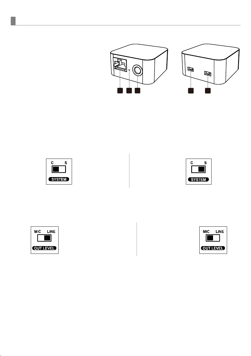
Parts and functions
Instructions
1.Installation with GM-143 microphones
The RJ45 port ①can be connected with a string of up to 10 GM-143 units.
2.CHAIRMAN-DELEGATE switch ④
▌Switch to C: The convertor’s system includes GM-143C (chairman unit).
▌Switch to S: The convertor’s system doesn't include GM-143C (chairman unit). All are GM-
143S (delegate unit).
including GM-143C
3.Audio output:¼” PHONE PLUG connector provides unbalanced audio output signal from
this jack to the mixer/amplifier. Use an audio output cable with ¼” PHONE PLUG connectors.
Connect one end from the unbalanced output jack ③of the audio convertor, and the other
end to the “LINE IN” or “MIC IN”jack of the mixer/ amplifier.
connecting to LINE /AUX IN connecting to MIC IN
Level switch setting: When connecting to the LINE /AUX IN of a mixer/amplifier, switch to
“LINE” position. DO NOT use the “MIC” position as they may not deliver a sufficient high
output level. When connecting to the “MIC IN” jack of a mixer/amplifier, switch to “MIC”
position. Overload distortion may occur at the wrong level position.
RJ45 port
Power indicator
3.Unbalanced audio output (Φ6.3mm)
4.
Chairman○
C-Delegate○
Sswitch
5.MIC/LINE output impedance switch
without GM-143C,
only GM-143S.


