5
Revised 04/15
CHIEF®
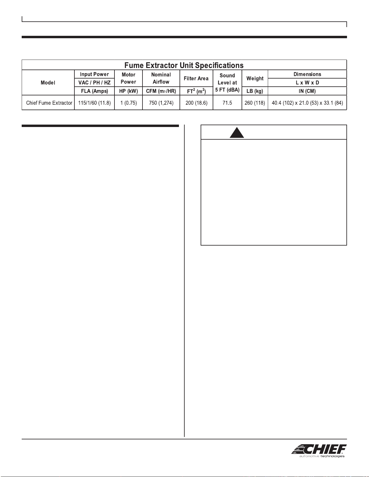
Fume Extractor
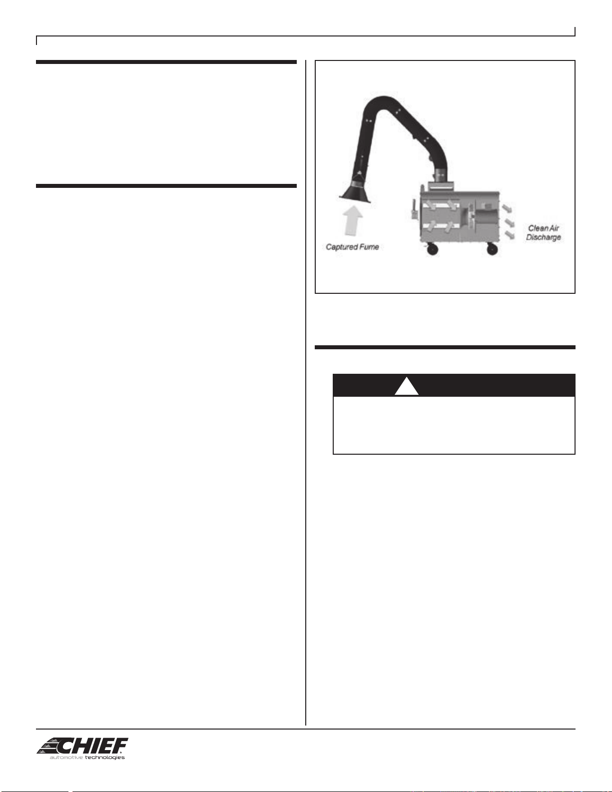
The position of the extraction hood is critical to the
overall performance of the fume extraction system.
The extraction arm and hood are designed to provide
maximum flexibility and convenience in operation. The
360° handle on the circumference of the hood should
be used to move the arm. Do not use the arm to move
or locate the fume extractor. Position the hood on the
opposite side of the weld target, approximately 10 –
14˝ from the fume source and at a 45° angle relative
to the welding surface, to draw the generated fume
away from the worker and avoid any airflow impedance.
Minimizing the bends present in the extraction arm will
reduce losses and improve extraction performance. Be
aware and minimize cross drafts or air movement that
may impact fume extraction such as cooling fans, HVAC
systems or open doors / windows.
6.4 EXTRACTION ARM DAMPER
Each extraction arm is equipped with an airflow damper
that can be used to control the airflow. Controlling
the airflow may be required to avoid disruption of the
arc gas during the welding process. The damper is
controlled by turning the handle of the right side of the
upper tube assembly. When the handle is perpendicular
to the duct, the damper is closed and open when in
parallel.
6.5 START-UP OPERATION
Roll the unit to the approximate location so that the
extraction arm can be proximate to the welding fume
source as described in Section 6.3. When in position,
engage the locking brakes located each front caster
(wheel) to secure the unit. Unwrap the power cord and
connect to a suitable electrical receptacle per Section
5.5. Adjust the fume extraction arm and hood in the
proper position and move the main power switch to the
On position to begin unit operation. Adjust the hood
location and damper position as necessary to achieve
proper fume extraction performance.
6.5.1 HOOD ACCESSORY KITS
If the hood switch and light kit option has been
installed, both the main power switch and the hood
switch will need to be on for the unit to operate. For
an arc sensor kit options that was installed for more
automated operation, place both the hood switch and
main power switch in the On position and the unit will
turn on once a welding arc is sensed and will remain
on for approximately 1 minute before shutting down if
additional arcs are not sensed
6.6 SHUT-DOWN AND STORAGE
To shut the fume extractor off, place the main power
switch into the off position. Unplug the power cord and
wrap the cord to the brackets located on the discharge
side of the unit. Compress the extraction arm into a
compact position and pivot above the fume extractor
unit. Release the front caster locking brakes and move
the unit to the storage location.
7.0 USER SERVICING INSTRUCTIONS
• Disconnect electrical power prior to servicing
equipment.
• Wear appropriate protective clothing.
• Collected particulate may be hazardous. Consult
proper authorities for handling and disposal.
• Disposal of collected particulate must be according
to federal, state and local regulations and all
appropriate authorities.
7.1 FILTER REPLACEMENT
• Removing the filters may expose you to hazardous
contaminants. Take all necessary precautions
including protective clothing such as eye protection
and gloves.
• Follow all local safety and environmental codes in
disposal of the accumulated particulate.
ProTura Nanofiber filters are the only replacement filters
which will provide the highest level of performance
expected from the fume extractor. Replacement
cartridge filters should be ordered when the differential
pressure is consistently above 4” w.g or system airflow
is inadequate to suitably capture and control the
welding fume.
1. Read and follow caution instructions in box above
before servicing your unit and refer to Figure 4 for
additional instruction.
2. Tap the metal surface of each filter access door to
dislodge collected particulate from the inner door
gasket. Pull the filter access door handle away from
the Fume extractor until the handle makes a 90°
angle with the door cover. The filter access door is
now in an unlatched position. Lift the filter access
door upward until the door rods clear the side
support brackets and pull the door away from the
Fume extractor. Tilt the door cover away from the
Fume extractor once free from the support brackets
to trap any dust on the inside of the filter access
door. Dispose of dust into a suitable container. Place
filter access door in a safe place.
3. Move filter from side to side to break the gasket seal
between filter and tubesheet (interior filter sealing
surface). Rotate the filter 180° to allow the dust on
top of the cartridge filter to fall into the bottom of the
fume extractor cabinet.
!DANGER
!CAUTION