China Nanfang Pump SZ Series User manual
SZ Fluorin Plastic Centrifugal Pump
Operation Manual
Hangzhou Nanfang Special Pump Industry Co., Ltd.
State High-tech Enterprise
1
TABLE OF CONTENTS
1
1
1
2
2
3
4
5
6
6
8
9
I Introduction
II. Application
III. Operation Conditions
IV. Structure Feature
V. Model Definition
VI. Structure
VII. Installation
VIII. Start and Operation
IX. Pump Starting Times
X. Maintenance and Service
XI. Trouble and Trouble Shooting
XII. Important Notice
Read this manual carefully before install, start the pump.
Standard:JB/T8688 (Fluorin plastic centrifugal pump)
I Introduction
SZ Fluorin plastic centrifugalpump adoptsexcellent hydraulic
structure. It is made by matureprocessing technology. Thewet partis
made of Fluorin plastic(F46 or F26). It is made by adding metalcore and
pressed and burned to a whole in one time. Theproduct hasthe following
benefit, smallvolume, runningreliable, highefficiency,energy saving,
easy to install and operate. Wide range of duty points for choosing. It
can transfer strongly corrosiveliquid suchas sulfuricacid, royalwater,
high and low temperatureresistance, advancedmechanical seal,little
hole when pressing welding, high efficiency, longservice time,etc.
alkali of any concentration. It has the following advantages, anti-corrosive,
II. Application
Thin liquid without fibre and grain
Petrol, chemical industry.
Pharmacy, pesticide, acid cleaning, dying industry.
Painting
Smelting, paper making, galvanization;
Suitable for strongly corrosive liquid such as hydrochloric acid, nitric
acid, sulfuric acid, choric acid, phosphoric acid, royal water, alkali,brine,
strong oxidant, organic solution, etc of any concentration.
III. Operation Conditions
Liquid temperature: -20 +120 ,
3
Flow range: 2~60m /h
Max head: 54m
33
Max medium density: 1.35 10 kg/m
Ambient temperature: Max +40
Altitude:Max.1,000m;
Pressure: Max 10 bar
When the specific gravity and density of the pumped liquid is bigger,
the shaft power will be increased, must use the appropriate motor.
2
IV. Structure Feature
SZ pump is single impeller centrifugal pump, axial suction and radical
discharge.
Simple structure, shaft is directly connected with impeller.
Easy for pipe works, inlet and outlet are connected by standard flanges.
V. Model Definition
SZ 50 32 160 S F46
Pump material
S: Three phase( 3kW is
220/380V; >3kW is 380V
D: Single phase 220V
Nominal diameter (mm)
of impeller
Discharge diameter(mm)
Suction diameter(mm)
Fluorin plastic centrifugal
pump
3
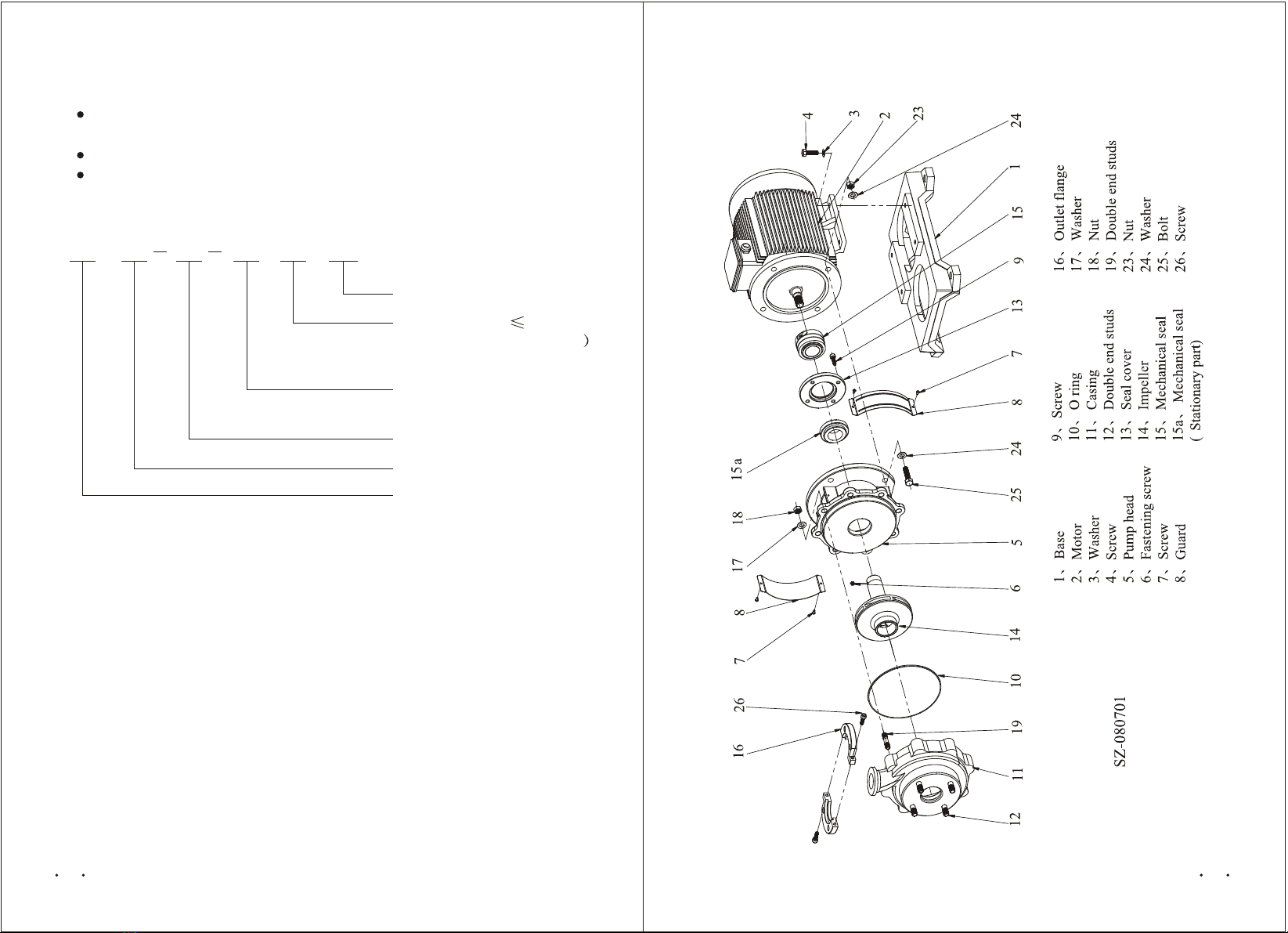
VI. Structure
SZ fluorin centrifugal pump is installed horizontally. Inlet and outlet
is connected by standard flanges inlet and outlet pipelines should be
supported separately. The weight of inlet and outlet must not be born by
pump itself.
When lifting or moving the pump, do not work it on the casing. You
can tight the motor rings or use steel string to tight the base to lift or move
the pump.
The installation height of the pump should be done according to the
requirement of NPSH, in order to prevent from cavitation corrosion
(Normally, the installation height should not be 3.5m higher than the liquid.)
If the position of the pump is higher than the liquid, a foot valve should
be installed in the suction, and fit screw hole and valve at the place of 0.3m
to 0.5m near the outlet for pouring liquid.
The pump installation should ensure that pump will not affected by
pipes force when operation.
Pump should be fixed stably on the base.
In order to ensure motor run well, pump should be installed at well-
ventilated and anti-frozen place.
2. Electrical connection
Before run pump, cables should be connected well, check voltage and
frequency.
Motor should be connected with a quick and efficient motor starter, to
ensure the motor will not be damaged by phase lack, unstable voltage and
overload.
VIII. Start and Operation
1.When the pump position is lower or same as the liquid level, before
start, open the valve at the suction pipeline to make the pump fully filled
with liquid, vent the air in the pump. If the position is higher than liquid
level, before start pull liquid to the pump from screw hole, to fill with the
pump fully and vent the air completely.
2.The outlet of the liquid should ensure the pump run continuously.
3.Check pump rotation direction.
Pump direction is indicated on the arrow on the pump, that is, viewing
from pump inlet, it is anti-clockwise.
Close outlet valve, start and stop the motor quickly, the direction can
be check from the rotating of the motor fan or coupling. After ensure the
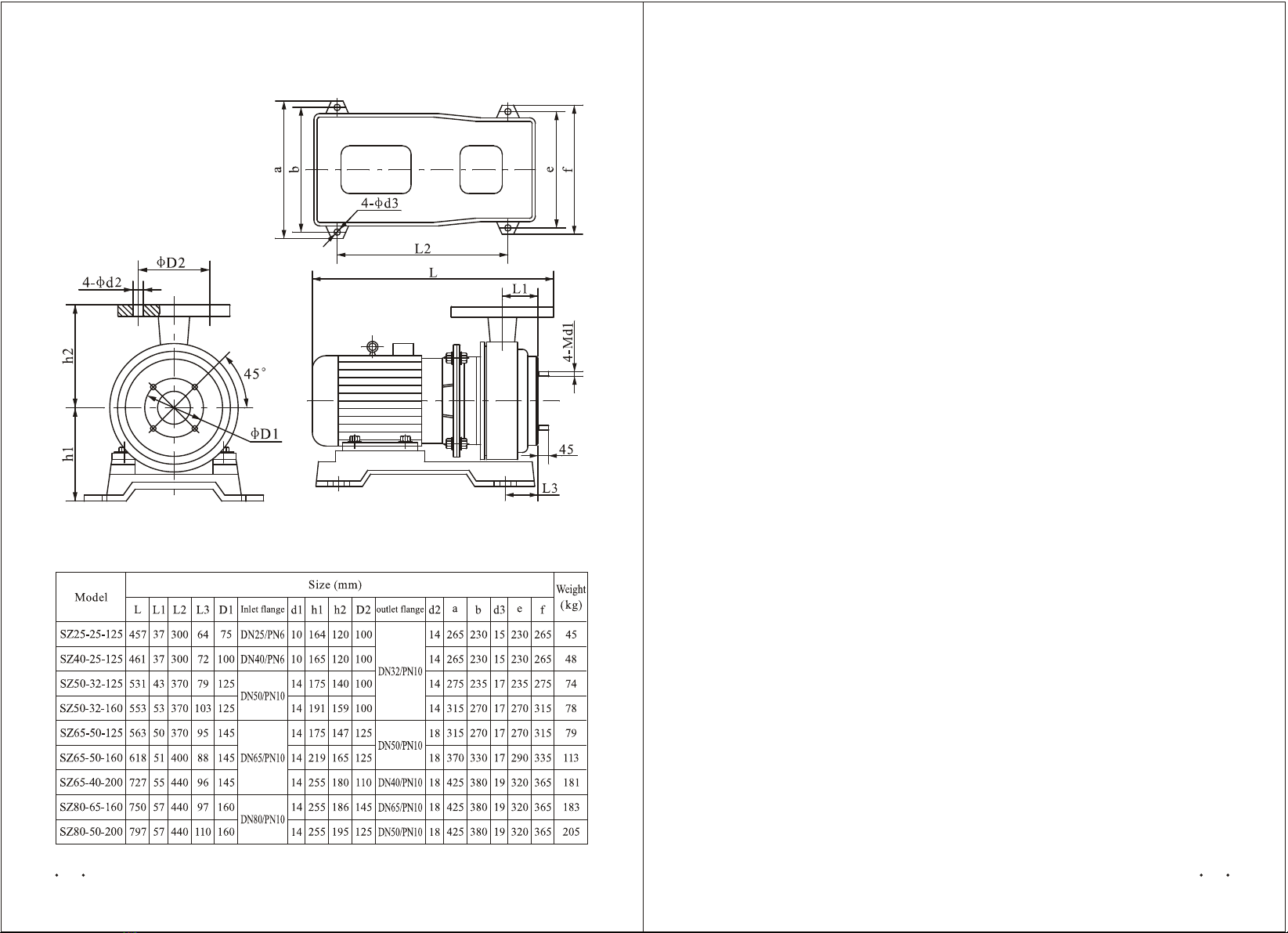
Figure 2 Pump installation and dimensions figure
Table 1 SZ pump dimensions
54
VII. Installation

turn 1 to 2 circles.
Unscrew the screws connecting motor and the base.
Unscrew the nut connecting casing and pump head, use a straight
screwdriver to open the casing slightly.
Unscrew the motor fan cover , take out the fans, use a key loc the shaft
at the motor side, and use a wrench unscrew the impeller, turn 2 circles.
Unscrew the screws connecting the motor and pump head.
Unscrew the impeller, takeout the pump head, take out the rotating part
of mechanical seal(do not unscrew the screws on the face of mechanical
seal), separate impeller and pump head, unscrew the seal cover of n the pump
head, take out the seal cover,take out the stationary part of mechanical seal.
3.When installation the pump, clean every parts, especially the touching
faces, reverse above steps to assemble a pump.
Clean the mechanical seal, put some PTFE washers, put it in the pump
head.
Note: The rubbing part is out, cover with seal cover, but do not screw it
very tighten to prevent from damaging the stationary part of mechanical seal.
Put on impeller, pumpon rotating part of mechanical seal(The faces of
mechanical seal should be cleaned and be lubricated with machine oil. Screw
the pump head and impeller on the motor,fasten them. When fastening the
nuts, pump head should be lifted a little to prevent from extended part of motor
shaft is not forced by pump head).
Fasten the screws connecting motor and pump head, fasten impeller loc
nuts, fit motor fan, cir-clip, fit motor fan cover.
Put on casing(put O ring in the casing in advance. If O ring is twisted,
broken, replace it with a new one and stick it with a silicon glue), put on
casing, tighten the nut, when tighten the nut, the casing should be laced evenly.
Screw the screws for motor and base, tighten it.
Use two small round rod at the left and right to press the rotating part
of mechanical seal, press appr. 1mm at the left and right, (make the spring
of mechanical seal compressed ), then loc the screws at the both sides of the
mechanical seal. After locked, check the clearance of both sides of mechanical
seal should be nearly same
Use hand to rotate motor shaft and impeller, ensure it is free, not blocked.
Fit the coupling guards.
rotation direction, start the pump. Then open the outlet valve slowly to the
required position. Attention: Pump can't work longer than two minutes
when the outlet valve is closed.
4.It is suggested that shut off the power when the outlet flow is 1/10
of the rated flow. Shut off the connected electrical meters and protective
devices. If the ambient temperature is lower than the frozen point of pumped
liquid, vent the liquid completely to prevent pump from frozen.
Pump is prohibited to run without liquid
IX. Pump Starting Times
In order to make the pump run well, it is suggested that, if the motor
power is equal or less than 4kW,the start times should less than 20 times in
an hour,if the motor power is bigger than 4kW, the start times should be
less than 10 times.
If the pump is not used for a long time, run pump at least twice in a year.
Before start, shut off power, use hand to rotate the coupling, ensure it runs
well. Then start the pump. The working time should not less than 0.2 hours.
X. Maintenance and Service
Mechanical seal is an important part of the pump, it is used in the liquid
that is clean and no floating grain. If it is new pipelines, clean the pipelines.
If the liquid maybe crystallize the mechanical seal, pump chamber should
be cleaned at least one time one day. If the pump is malfunction or need to
be check, please do as follows.
1.Normal check
Shut off power
Check inlet of the pump, to see if it is blocked by fibers. Check if inlet
is cracked or blocked.
Check pump outline to see if it is damaged, check if motor case is
corrosive, check if cable is disconnected.
Unscrew the screw of one coupling guard, take out the coupling guard,
use hand to rotate the pump shaft or pump coupling, to ensure it turns freely
without rubbing noise.
2.Pump dissemble and check :
Unscrew coupling guard, take out the coupling guard.
Unscrew the tighten screw near 10mm from the impeller, turn 3 to 4
circles, unscrew the 2 socket hex screws at the side of the mechanical seal,
76

XI. Trouble and TroubleShooting
Faults Possible reason Solutions Remark
Pump can't
be started
1.Power supply broken.
2.Fuse defected.
3.Motor switches off for
overload.
4.Controlling circuit is
broken or parts broken.
1.Check power supply.
2.Replace fuse, if fuse is down
again, open the pump to check.
3.Check power voltage, restart
it again.
4.Check controlling device.
1.Pump parts are rubbing.
2.The density of pumping
liquid is not suitable the
pump.
3.Too big flow
1.Too low sets for the
overload device.
2.Power supply failed
periodically.
3.Low voltage when
power supply is
consumed in the high
way.
1.Base is not strong.
2.Pump turns reversely.
3.Pump parts are rubbing.
4.The suction height is
too high or not enough
liquid filled.
5.Pump part is loose or
damaged.
1.There is not enough
liquid at suction.
2.Liquid level is too low.
3.Suction is blocked by
impurities.
1.Impeller is damaged.
2.Pump runs reversely.
3.Suction is blocked by
impurities.
4.Pipes are blocked or
there is leakage
5.Choose the wrong
model.
Cost too
much power
when
running
Overload
device trip
out
occasionally.
There is
noise in the
pump and
pump is
vibrated
abnormally.
The liquid
do not flow
evenly.
Insufficient
flow
1.Check parts.
2.Recalculate and replace with a
suitable motor.
3.Operate the pump in the flow
range.
1.Reset the overload device.
2.Check power supply.
3.Add a voltage stabilization
device.
1.Stable the base.
2.Check the rotation direction of
the pump.
3.Check pump.
4.Lower the location of the pump
or refill the pump to vent the
air in the pump.
5.Take out the loosing part,
replace damaged parts.
1.Improve system, add liquid.
2.Higher the liquid level.
3.Check and get rid of impurities.
1.Replace with a new impeller.
2.Check rotation direction.
3.Clean suction.
4.Check and repair pipes.
5.Re-choose the model
For first case,
user should not
service by
himself without
permission.
For case 3 and
case 5, user
should not
service by
himself without
permission.
XII. Important Notice
1.Customers will not be advised if this manual is updated.
2.Pump will be guaranteed for one year under normal operation with
the correct model. Wearing parts are not included.
3.Users shall be responsible for the damage if they dissemble the pumps
by themselves in guaranteed period.
Pump runs
with no
water.
Device trips
out or start
load is too
much.
Pumps no
water
There is
noise in the
pump and no
water out
1.Too big flow.
2. Too much resistance on
suction.
3. Suction height is too high.
4. The is air coming in the
suction.
1.Discharge valve is
closed.
2.No water sucked or
liquid level is too low.
3.Not fill liquid or not
filled enough liquid.
4.Suction blocked.
5.Pump damaged.
1.Fuse is down.
2.There is something
wrong with contact of
overload device.
3.Power supply cable is
loose or power supply
defected.
4.Motor windings are
defected.
5.Pump parts are blocked.
6.Haven't closed the
discharge valve when
start.
1.Suction is blocked by
impurities.
2.Discharge valve is
closed completely.
1.Check and clean.
2.Open valve.
1.Replace fuse.
2.Check starter.
3.Check cables and power supply.
4.Replace motor
5.Check pump.
6.Close valve and re-start.
1.Open discharge valve.
2.Adjust pump location.
3.Refill the liquid and vent the air
in the liquid.
4.Clean suction.
5.Repair of replace
1.Close the discharge valve a little.
2. Check suction pipes and suction
valve.
3. Lower the suction height.
4. Check suction pipes or suction
flange connections.
For case 5, user
should not
service by
himself without
permission.
For case 4 and
case 5, user
should not
service by
himself without
permission.
98
This manual suits for next models
9
Table of contents
Popular Water Pump manuals by other brands

BearCat Pumps
BearCat Pumps 110 Series manual

Giant
Giant P200A-5100 Series Repair and operating instructions

GORMAN-RUPP PUMPS
GORMAN-RUPP PUMPS 811/2B3-B Installation, operation, and maintenance manual with parts list

dosatron
dosatron D40MZ3000 manual

Steffens
Steffens Pomona Original user manual

Dover
Dover PSG Wilden PS800 Engineering, operation & maintenance


