turck TBEN-L Series User manual

Your Global Automation Partner
Instructions for Use
TBEN-L…-4RFID…-LNX
Compact RFID Interface

2Hans Turck GmbH & Co. KG | T +49 208 4952-0 | F +49 208 4952-264 | [email protected] | www.turck.com

V01.01 | 2019/05 3
Contents
1 About these Instructions................................................................................................................ 5
1.1 Target groups................................................................................................................ 5
1.2 Explanation of symbols used ..................................................................................... 5
1.3 Other documents ......................................................................................................... 5
1.4 Feedback about these instructions........................................................................... 5
2 Notes on the Product......................................................................................................................6
2.1 Product identification.................................................................................................. 6
2.2 Scope of delivery .......................................................................................................... 6
2.3 Legal requirements...................................................................................................... 6
2.4 Manufacturer and service........................................................................................... 6
3 For Your Safety................................................................................................................................. 7
3.1 Intended use.................................................................................................................. 7
3.2 General Safety Notes ................................................................................................... 7
4 Product Description ........................................................................................................................ 8
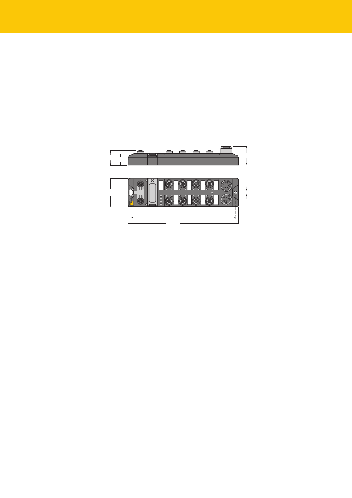
4.1 Device overview ........................................................................................................... 8
4.1.1 Operating elements .....................................................................................................................8
4.2 Properties and features............................................................................................... 8
4.3 Operating principle...................................................................................................... 9
4.4 Functions and operating modes ...............................................................................9
4.4.1 Linux distribution – Software components.........................................................................9
4.5 USB Host Port ................................................................................................................ 9
4.6 Technical Accessories .................................................................................................. 9
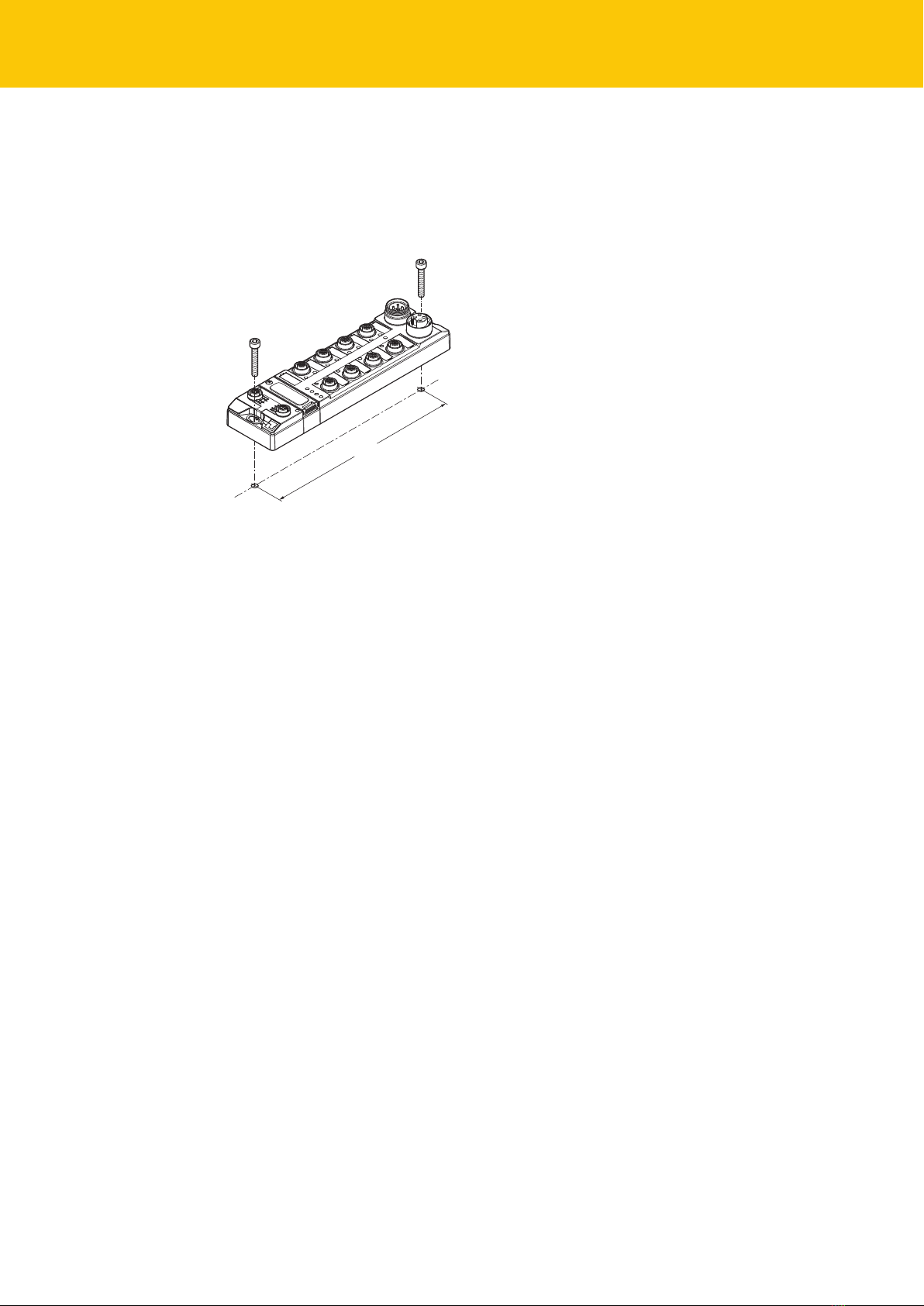
5 Mounting.........................................................................................................................................10
5.1 Mounting the device outdoors................................................................................10
5.2 Grounding the device................................................................................................11
5.2.1 Grounding and shielding concept....................................................................................... 11
5.2.2 Grounding the device (FG) ..................................................................................................... 12
6 Connection......................................................................................................................................13
6.1 Connecting the modules to Ethernet .....................................................................13
6.2 Connecting the power supply .................................................................................14
6.3 Connecting RFID read/write heads.........................................................................15
6.4 Connecting digital sensors and actuators.............................................................16
7 Commissioning ..............................................................................................................................17
7.1 Setting the IP address................................................................................................17
7.1.1 Setting the IP address via switches at the device........................................................... 17
7.1.2 Setting the IP address via the Turck Service Tool........................................................... 19
7.2 Programming RFID channels ...................................................................................20
7.2.1 GPIOs of the RFID channels – Overview ............................................................................ 21
7.2.2 Adapt slave controller via script ........................................................................................... 22
7.2.3 Programming RFID channels with Python 3.................................................................... 24
7.2.4 Programming RFID channels with Node.js....................................................................... 25
7.2.5 Programming RFID channels with C or C++ .................................................................... 26
7.3 Programming digital channels (DXP).....................................................................28
7.3.1 GPIOs of the DXP channels – Overview ............................................................................. 28

Contents
4Hans Turck GmbH & Co. KG | T +49 208 4952-0 | F +49 208 4952-264 | [email protected] | www.turck.com
7.3.2 Setting DXP functions via script ........................................................................................... 29
7.3.3 Programming DXP channels with Python 3..................................................................... 30
7.3.4 Programming DXP channels with Node.js........................................................................ 32
7.3.5 Programming DXP channels with C or C++..................................................................... 34
7.4 Programming LED functions....................................................................................37
7.4.1 LEDs – Overview......................................................................................................................... 37
7.4.2 Setting LED functions via a script......................................................................................... 37
7.4.3 Programming LED functions with Python 3..................................................................... 38
7.4.4 Programming LED functions with Node.js ....................................................................... 39
7.4.5 Programming LED functions with C or C++..................................................................... 40
7.5 Creating a C application............................................................................................41
7.6 Starting the application automatically (Autostart) .............................................42
7.6.1 Autostart – Creating the configuration file (unit file) ................................................... 42
7.6.2 Example: Using the unit file ................................................................................................... 43
7.6.3 Activating the unit file.............................................................................................................. 43
7.7 Managing access rights.............................................................................................43
7.8 Installing Python packages ......................................................................................44
7.8.1 Example: Installing the Python module............................................................................. 44
8 Setting .............................................................................................................................................47
9 Operation ........................................................................................................................................48
9.1 LEDs...............................................................................................................................48
9.2 Reset device (Reset) ...................................................................................................48
10 Troubleshooting ............................................................................................................................49
11 Maintenance...................................................................................................................................50
11.1 Executing the firmware update via the USB interface ........................................50
11.2 Carrying out a firmware update via the console..................................................50
11.2.1 Example: Carrying out a firmware update with WinSCP and PuTTY....................... 51
12 Repair...............................................................................................................................................57
12.1 Returning devices.......................................................................................................57
13 Disposal ...........................................................................................................................................57
14 Technical Data................................................................................................................................58
15 Appendix: Declaration of Conformity .......................................................................................60
16 Appendix: Example – “HelloGPIO” for Node.js ........................................................................61

V01.01 | 2019/05 5
1 About these Instructions
These operating instructions describe the structure, functions and the use of the product and
will help you to operate the product as intended. Read these instructions carefully before using
the product. This is to avoid possible damage to persons, property or the device. Retain the in-
structions for future use during the service life of the product. If the product is passed on, pass
on these instructions as well.
1.1 Target groups
These instructions are aimed a qualified personal and must be carefully read by anyone
mounting, commissioning, operating, maintaining, dismantling or disposing of the device.
1.2 Explanation of symbols used
The following symbols are used in these instructions:
DANGER
DANGER indicates a dangerous situation with high risk of death or severe injury if
not avoided.
WARNING
WARNING indicates a dangerous situation with medium risk of death or severe in-
jury if not avoided.
CAUTION
CAUTION indicates a dangerous situation of medium risk which may result in minor
or moderate injury if not avoided.
NOTICE
NOTICE indicates a situation which may lead to property damage if not avoided.
NOTE
NOTE indicates tips, recommendations and useful information on specific actions
and facts. The notes simplify your work and help you to avoid additional work.
uCALL TO ACTION
This symbol denotes actions that the user must carry out.
aRESULTS OF ACTION
This symbol denotes relevant results of actions.
1.3 Other documents
Besides this document the following material can be found on the Internet at www.turck.com:
nData sheet
nEC Declaration of Conformity
1.4 Feedback about these instructions
We make every effort to ensure that these instructions are as informative and as clear as pos-
sible. If you have any suggestions for improving the design or if some information is missing in
the document, please send your suggestions to [email protected].

Notes on the Product
6Hans Turck GmbH & Co. KG | T +49 208 4952-0 | F +49 208 4952-264 | [email protected] | www.turck.com
2 Notes on the Product
2.1 Product identification
These instructions apply to the following compact RFID interfaces:
nTBEN-L4-4RFID-8DXP-LNX
nTBEN-L5-4RFID-8DXP-LNX
2.2 Scope of delivery
nCompact RFID interface
nClosure caps for M12 connectors
nQuick Start Guide
2.3 Legal requirements
The device is subject to the following EC directives:
n2014/30/EU (electromagnetic compatibility)
n2011/65/EU (RoHS II Directive)
2.4 Manufacturer and service
Hans Turck GmbH & Co. KG
Witzlebenstraße 7
45472 Muelheim an der Ruhr
Germany
Turck supports you with your projects, from initial analysis to the commissioning of your applic-
ation. The Turck product database contains software tools for programming, configuration or
commissioning, data sheets and CAD files in numerous export formats. You can access the
product database at the following address: www.turck.en/products
For further inquiries in Germany contact the Sales and Service Team on:
nSales: +49 208 4952-380
nTechnology: +49 208 4952-390
Outside Germany, please contact your local Turck representative.

V01.01 | 2019/05 7
3 For Your Safety
The product is designed according to state-of-the-art technology. However, residual risks still
exist. Observe the following warnings and safety notices to prevent damage to persons and
property. Turck accepts no liability for damage caused by failure to observe these warning and
safety notices.
3.1 Intended use
The devices are intended for use in the industrial sector.
The TBEN-L…-4RFID-8DXP-LNX... block module is a programmable RFID interface for use in the
Turck RFID system. The Turck RFID system is used for the contactless exchange of data between
a tag and a read/write head in object or product identification applications. Four RFID channels
are provided for connecting BL ident® read/write heads. Eight configurable digital channels are
also provided. The interfaces communicate via TCP/IP with third party systems such as ERP sys-
tems.
The devices may only be used as described in these instructions. Any other use is not in accord-
ance with the intended use; Turck accepts no liability for any resulting damage.
3.2 General Safety Notes
nThe device may only be assembled, installed, operated, parameterized and maintained by
professionally-trained personnel.
nThe device may only be used in accordance with applicable national and international regu-
lations, standards and laws.
nThe device only meets the EMC requirements for industrial areas and is not suitable for use
in residential areas.

Product Description
8Hans Turck GmbH & Co. KG | T +49 208 4952-0 | F +49 208 4952-264 | [email protected] | www.turck.com
4 Product Description
The devices are designed with a fully encapsulated housing with degree of protection IP67/
IP69K. Four RFID channels are provided for connecting read/write heads. It is also possible to
connect sensors and actuators via eight digital I/O channels, which can be configured as inputs
or outputs as required. The terminals for the read/write heads and for digital I/Os are M12 sock-
ets. An M12 socket is provided for the Ethernet connection. The plug connectors are 4-pin
(TBEN-L4) or 5-pin (TBEN-L5) 7/8” female connectors.
4.1 Device overview
218
230.5
C4C5C6C7
6.3
38.8
60.4
C0C1C2C3
24
30.2
X2
X1
P2
P1
Fig.1: Dimensions
4.1.1 Operating elements
The devices are provided with the following operating elements:
nRotary coding switches and DIP switch for setting the IP address
nSET button for activating the write accesses of the USB Host port functions
4.2 Properties and features
nTCP/IP
nFreely programmable compact module based on Linux
nProgramming languages C, C++, NodeJS, Python
nAPI and SDK available on request
nImplementation of the protocol for the read/write heads required
n4 channels with M12 connector for RFID
n8 configurable digital channels as 2A pnp inputs and/or outputs
nMultiple LEDs for status display
nIntegrated Ethernet switch enables line topology
n10 Mbps/100 Mbps transfer rate
nGlass fiber reinforced housing
nShock and vibration proof
nFully encapsulated module electronics
nDegree of protection IP65/IP67/IP69K

V01.01 | 2019/05 9
4.3 Operating principle
The RFID interfaces connect the RFID system with other systems that communicate via TCP/IP
(e.g. ERP systems). The interfaces are provide with an Ethernet interface and RFID interfaces.
The RFID system can be linked to a third-party system, such as an ERP system, via the TCP/IP in-
terface. The read/write heads are connected to the interfaces via the RFID interfaces. The inter-
faces can also process sensor and actuator signals via 8 configurable digital channels.
4.4 Functions and operating modes
HF and UHF read/write heads can be connected to the RFID channels. Parallel operation of HF
and UHF read/write heads on the same device is also possible.
Sensors and actuators can be connected to the configurable digital channels. Up to four 3-wire
PNP sensors or four PNP DC actuators with a maximum output current of 2 A per output can be
connected. The Linux operating system enables the device functions to be programmed with C,
C++, NodeJS or Python. It is also possible to integrate middleware functions on the device.
4.4.1 Linux distribution – Software components
The Linux distribution of the device contains the following software components:
nSSH
nSFTP
nHTTP
nIBTP
nMTXP
nDHCP
nSNTP
nNode.js 6.9.5 (LTS)
nPython 3.x
4.5 USB Host Port
The device is provided with a USB Host port for connecting USB memory sticks. The USB Host
port is a USB2.0 A socket. The firmware of the devices can be updated via the USB interface.
Memory expansion via the USB Host port is not possible.
4.6 Technical Accessories
Accessories for mounting, connecting and parameterizing can be found in product database or
the Accessories List for TBEN (D301367) under www.turck.com. The accessories are not part of
the scope of delivery.

Mounting
10 Hans Turck GmbH & Co. KG | T +49 208 4952-0 | F +49 208 4952-264 | [email protected] | www.turck.com
5 Mounting
The device must be attached to a level, pre-drilled and grounded mounting surface.
Attach the module to the mounting surface with two M6 screws. The maximum tighten-
ing torque for the screws is 1.5 Nm.
218 [5.58]
M6 (2x)
max. 1.5 Nm
Fig.2: Fixing the device to the mounting plate
5.1 Mounting the device outdoors
The device is UV-resistant according to DIN EN ISO 4892-2. Direct sunlight can cause material
abrasion and color changes. The mechanical and electrical properties of the device are not af-
fected.
To avoid material abrasion and color changes: Protect the device from direct sunlight,
e.g. by using protective shields.

V01.01 | 2019/05 11
5.2 Grounding the device
5.2.1 Grounding and shielding concept
The grounding and shielding concept of the TBEN-L modules enables the separate grounding
of the fieldbus and I/O section.
1 nF
2,2 MΩ
X1
C0
C1
C2
C3
P1
X2
C4
C5
C6
C7
P2
4 x 15 nF
Fig.3: Equivalent circuit, shielding concept
1
2
3
Fig.4: Grounding components
The grounding strip (1) on the M12 plug connectors for the fieldbus connection (P1, P2) con-
nects the shield of the fieldbus cables. The metal ring (2) is fitted underneath the grounding
strip and connects the functional ground of the 7/8” plug connectors (Pin 3) for the power sup-
ply with the functional ground of the M12 plug connectors (Pin 5) for connecting the read/
write heads, sensors and actuators. A metal screw (3) connects the device with the reference
potential of the system.

Mounting
12 Hans Turck GmbH & Co. KG | T +49 208 4952-0 | F +49 208 4952-264 | [email protected] | www.turck.com
5.2.2 Grounding the device (FG)
Grounding strip and metal ring are connected to each other. A fixing screw through the bottom
mounting hole of the module connects the shield of the fieldbus cables with the functional
ground of the power supply and connected devices as well as the reference potential of the
system. If a common reference potential is not required, remove the grounding clip to discon-
nect the fieldbus shield or fasten the module with a plastic screw.
Removing the grounding clip
Lever up the grounding strip with a flat slot-head screwdriver and remove.
Fig.5: Removing the grounding clip
Mounting the grounding clip
Use a screwdriver to insert the grounding clip between the fieldbus connectors so that
contact is made with the metal housing of the plug connectors.
aThe shield of the fieldbus cables is connected to the grounding clip.
Fig.6: Mounting the grounding clip

V01.01 | 2019/05 13
6 Connection
6.1 Connecting the modules to Ethernet
The connection to Ethernet is realized via the integrated auto-crossing switch is done using two
4-pole, D-coded M12 x 1-Ethernet-connectors. The maximum tightening torque is 0.6 Nm.
Fig.7: M12 Ethernet connector for the connection to Ethernet
Connect the device to Ethernet according to the pin assignment below.
v
4
13
2
P1, P2
1 = TX +
2 = RX +
3 = TX –
4 = RX –
flange = FE
Fig.8: Pin assignment Ethernet connectors

Connecting
14 Hans Turck GmbH & Co. KG | T +49 208 4952-0 | F +49 208 4952-264 | [email protected] | www.turck.com
6.2 Connecting the power supply
For the connection to the power supply, the device has two 5-pin 7/8" connectors. The power
supply connectors are designed as 4-pole (TBEN-L4) or 5-pole (TBEN-L5) 7/8" connectors. V1
and V2 are galvanically isolated. The maximum tightening torque is 0.8 Nm.
Fig.9: 7/8’’ connector for connecting the supply voltage
Connect the device to the voltage supply according to the pin assignment below.
w v
1
2
3
4
1 RD = 24 VDC V2
2 GN = 24 VDC V1
3 WH = GND V1
4 BK = GND V2
1
2
3
4
X1 X2
Fig.10: TBEN-L4-… – Pin assignment power supply connectors
1 BK = GND V2
2 BU = GND V1
3 GNYE = FE
4 BN = 24 VDC V1
5 WH = 24 VDC V2
3
4
5
2
1
w v
3
4
5
2
1
X1 X2
Fig.11: TBEN-L5-… – Pin assignment power supply connectors
Connector Function
X1 Power feed
X2 Continuation of the power to the next node
V1 System supply: Power supply 1 (incl. supply of electronics)
V2 Load voltage: Power supply 2
NOTE
The system voltage (V1) and the load voltage (V2) are supplied and monitored sep-
arately. In case of an undercut of the admissible voltage, the connectors are
switched-off according to the module's supply concept. In case of an undervoltage
at V2, the LED PWR changes from green to red. In case of an undervoltage at V1, the
LED PWR is turned off.

V01.01 | 2019/05 15
6.3 Connecting RFID read/write heads
The device has four 5-pin M12 plug connectors for connecting RFID read/write heads. The max-
imum tightening torque is 0.8Nm.
Connect the read/write heads to the device as per the pin layout shown below.
4
1 3
2
5
v
1 = Vaux1
2 = Data B
3 = GND V1
4 = Data A
5 = FE/Shield
Fig.12: RS485 – Pin layout of the read/write head connections
4
13
2
5
v
1 = BN (+)
2 = BK (Data)
3 = BU (GND)
4 = WH (Data)
5 = shield
Fig.13: …/S2500 connection cables – Pin layout of the read/write head connections
4
13
2
5
v
1 = BN (+)
2 = WH (Data)
3 = BU (GND)
4 = BK (Data)
5 = shield
Fig.14: …/S2501 connection cables – Pin layout of the read/write head connections
4
1 3
2
5
v
1 = RD (+)
2 = BU (Data)
3 = BK (GND)
4 = WH (Data)
5 = shield
Fig.15: …/S2503 connection cables – Pin layout of the read/write head connections

Connecting
16 Hans Turck GmbH & Co. KG | T +49 208 4952-0 | F +49 208 4952-264 | [email protected] | www.turck.com
6.4 Connecting digital sensors and actuators
The device has four 5-pin M12 plug connectors for connecting digital sensors and actuators.
The maximum tightening torque is 0.8Nm.
Fig.16: M12 plug connector for connecting digital sensors and actuators
Connect the sensors and actuators to the device as per the pin layout below.
4
13
2
5
v
1 = Vaux2
2 = Signal In/Out
3 = GND V2
4 = Signal In/Out
5 = FE
C2...C3
5 FE 4 BK
1 BN +
3 BU –
3 BU –
2 WH
v
C2…C3
Sensor
or
Actuator
Sensor
or
Actuator
Fig.17: Connections for digital sensors and ac-
tuators – Pin layout
Fig.18: Connections for digital sensors and ac-
tuators – Wiring diagram
The channels are assigned to the slots as follows:
Channel Slot Pin
DXP8 Ch8 C4 4
DXP9 Ch9 C4 2
DXP10 Ch10 C5 4
DXP11 Ch11 C5 2
DXP12 Ch12 C6 4
DXP13 Ch13 C6 2
DXP14 Ch14 C7 4
DXP15 Ch15 C7 2

V01.01 | 2019/05 17
7 Commissioning
The Linux operating system enables the device functions to be programmed with C, C++,
NodeJS or Python.
Additional software tools (e.g. PuTTY) are required to access the device via the console. A file
exchange between the device and a PC can be used, e.g. via WinSCP. The following login data
is stored on the device by default:
User: user
Password: password
NOTE
The read/write head protocol is not implemented by default. The protocol must be
implemented by the user.
7.1 Setting the IP address
The IP address can be set via two decimal rotary coding switches and DIP switches on the
device, via the web server or via the Turck Service Tool.
7.1.1 Setting the IP address via switches at the device
The IP address can be set via two decimal rotary coding switches and the DIP switch "Mode" on
the device. The switches are located under a cover together with the USB ports and the SET
button.
5
4321
0
9
8
7
6
5
4321
0
9
8
7
6
2 1
3
ON
SRV
USB Host
Set
Mode
x 10
x 1
Fig.19: Switches for setting the IP address
Open the cover above the switches.
Set the rotary coding switch to the desired position according to the table below.
Set DIP switch "Mode" to the desired position according to the table below.
Execute a power cycle.
NOTICE! When the cover over the rotary coding switches is open, protection class IP67 or
IP69K is not guaranteed. Damage to the device due to invasive foreign material or liquids
Tightly close the cover above the switches.

Commissioning
18 Hans Turck GmbH & Co. KG | T +49 208 4952-0 | F +49 208 4952-264 | [email protected] | www.turck.com
Addressing options
The IP address of the devices can be set in different ways. The following addressing options can
be selected via the switches on the device. Changes to the settings become active after a
voltage reset.
Setting option DIP switch “MODE” Rotary coding
switches
Description
Default address 0 00 IP address: 192.168.1.100
Subnet mask: 255.255.255.0
Gateway: 192.168.1.1
Rotary mode 0 1…99 In rotary mode, the last byte of the IP address can
be set manually at the gateway. The other network
settings are stored in the non-volatile memory of
the gateway and cannot be changed in rotary
mode. Addresses from 1...99 can be set.
DHCP mode 1 40 In DHCP mode, the IP address is automatically as-
signed by a DHCP server in the network. The subnet
mask assigned by the DHCP server and the default
gateway address are stored non-volatile in the
memory of the gateway DHCP supports 3 types of
IP address assignment:
nAutomatic address assignment: The DHCP server
assigns a permanent IP address to the client.
nDynamic address assignment: The IP address as-
signed by the server is only reserved for a certain
period of time. After this time has elapsed or
after the explicit release by a client, the IP ad-
dress is reassigned.
nManual address assignment: A network adminis-
trator assigns an IP address to the client. In this
case, DHCP is only used to transmit the assigned
IP address to the client.
PGM Mode 1 50 In PGM mode, the complete IP address is assigned
manually via the Turck Service Tool, FDT/DTM or via
a web server. In PGM mode, the set IP address and
the subnet mask are stored in the memory of the
gateway. All network settings (IP address, subnet
mask, default gateway) are taken from the internal
EEPROM of the module.
PGM DHCP mode 1 60 In PGM-DHCP mode, the gateway sends DHCP re-
quests until it is assigned a fixed IP address. The
DHCP client is automatically deactivated if an IP ad-
dress is assigned to the gateway via the DTM or a
web server.
F_Reset 1 90 The F_Reset mode sets all device-settings back to
the default values and deletes all data in the
device's internal flash. The following values are re-
set or deleted:
nIP address and subnet mask
nParameters
Restore 1 00 nIP address: 192.168.1.100

V01.01 | 2019/05 19
7.1.2 Setting the IP address via the Turck Service Tool
Connect the device to a PC via the Ethernet interface.
Launch the Turck Service Tool.
Click Search or press F5.
Fig.20: Turck Service Tool – Start screen
The Turck Service Tool displays the connected devices.
Fig.21: Turck Service Tool – Found devices
Click the required device.
Click Change or press [F2].
NOTE
Clicking the IP address of the device opens the web server.

Commissioning
20 Hans Turck GmbH & Co. KG | T +49 208 4952-0 | F +49 208 4952-264 | [email protected] | www.turck.com
Change the IP address and if necessary the network mask and gateway.
Accept the changes by clicking Set in device.
Fig.22: Turck Service Tool – Changing the device configuration
7.2 Programming RFID channels
The RFID channels of the device are designed as RS485 serial interfaces. The interface operates
in half-duplex mode. The direction of the control signal must be adjusted to switch between
send and receive.
An external peripheral device is integrated in the RFID interface in order to communicate with
connected devices. A separate slave controller is used for handling the messages exchanged
between the interface and the read/write head. The slave controller must be adapted to the
Linux settings via a script.
The serial interfaces are as follows:
COM interface TTY Channel
COM0 tty03 Ident 0
COM1 tty04 Ident 1
COM2 tty01 Ident 2
COM3 tty02 Ident 3
Other manuals for TBEN-L Series
2
This manual suits for next models
2
Table of contents
Other turck Recording Equipment manuals

turck
turck TX715FB-P3CV01 User manual

turck
turck TBEN-S2-2RFID-4DXP User manual

turck
turck TBEN-L5-4RFID-8DXP-CDS User manual

turck
turck TBEN-LL-4RFID-8DXP User manual

turck
turck EZ-track User manual

turck
turck TBEN-L5-4RFID-8DXPOPC-UA User manual

turck
turck TBEN-S2-2RFID-4DXP User manual

turck
turck TBEN-L 4RFID-8DXP Series User manual

turck
turck TX500 Series User manual

turck
turck TBEN-S2-2RFID-4DXP User manual