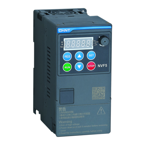
CHINT NVF2G-S Series User manual

Standard: EC 61800-3
NO:2023.07
NVF2G-S Series
Inverter
User's Guide

NVF2G-S series vector control inverter produced by Zhejiang Chint Electric Co., Ltd. !
NVF2G-S series inverters have V/F control and speed sensorless vector control technology, which
not only has high speed response and good low-frequency torque performance, but also has the
characteristics of convenient parameter debugging and simple and easy-to-use functions. At the same
time, the reliability and environmental adaptability have been strengthened, which can meet the
applications of fans, water pumps, mines, air compressors, HVAC and so on.
This manual introduces the functional characteristics and usage methods of NVF2G-S series inverters,
including product selection, installation and commissioning, parameter function description, etc. Please
read this manual carefully before using the inverter to ensure correct use of the inverter. After reading
and using this manual, please keep it properly for future use. If you encounter difficulties and problems
that cannot be solved during use, please contact the company's local distributors or directly contact the
company's professional and technical personnel for help. (400 customer service hotline: 400-817-7777)
The company reserves the right to continuously optimize and improve the NVF2G-S series inverters,
and the information is subject to change without prior notice.
Foreword

The product is strictly prohibited to be installed in an environment containing flammable and
explosive gas, moisture condensation, and it is strictly prohibited to operate the product with
wet hands.
When the product is working, it is strictly forbidden to touch the conductive part of the product.
When installing, maintaining and maintaining the product, it is necessary to ensure that the line
is powered off.
It is strictly forbidden for children to play with the unpacked product or packaging.
Sufficient space and safety distance should be reserved around the product installation.
Do not install it where the gas medium can corrode metal and damage insulation.
When the product is installed and used, standard wires must be used, and the power supply and
load that meet the requirements must be connected.
In order to avoid dangerous accidents, the installation and fixing of the product must be carried
out in strict accordance with the requirements of the manual.
After unpacking, inspect the product for damage and check the integrity of the item.
When installing live wires outside the product, in order to prevent electric shock, please insulate
the exposed wires.
If the inverter is damaged or its components are incomplete, please do not install and run it,
otherwise there is a risk of fire and injury.
Do not install in places where water droplets may splash, such as direct sunlight or water pipes,
otherwise there is a risk of damage to the equipment;
Do not short-circuit + and B. It is strictly forbidden to connect terminals other than RIA, RIB, R1C,
R2A, R2B, and R2C to AC 220V signals, otherwise there is a risk of damage to the equipment.
When transporting, do not let the operation panel and cover plate be stressed, otherwise there is
a risk of damage to the equipment and injury when falling.
Please install it in a place that can bear the weight of the inverter, otherwise there is a risk of
damage to the equipment and injury when it falls.
Before leaving the factory, all inverters have been tested for withstand voltage, and it is forbidden
to conduct withstand voltage tests for inverters, otherwise there is a risk of damage to the equipment.
When the length of the motor cable is greater than 100 meters, multi-twisted wires must be used
and an AC output reactor that can suppress high-frequency oscillation must be installed. Avoid
motor insulation damage, excessive leakage current and frequent inverter protection.
After replacing the control board, the parameters must be set correctly before running, otherwise
there is a risk of damage to the equipment.
Safety Alert

Safety Alert
It is forbidden for non-professional technicians to test the signal during operation , otherwise there
is a risk of injury or equipment damage.
It is not allowed to control the start and stop of the inverter by frequently turning on and off the
power, otherwise there is a risk of damage to the equipment.
In a domestic environment this product may cause radio interference, in which case additional
suppression measures (chokes, filters, etc.) may be required.
The electrolytic capacitor of the main circuit and the electrolytic capacitor on the printed circuit
board may explode when incinerated, and the panel and other plastic parts will produce toxic gas
when incinerated. Please dispose of it as industrial waste.
logo illustrate
Danger! Please be sure to read the user manual before installation and operation.
Danger! Do not remove the upper cover when the power is on or within 10 minutes
after the power is cut off.

001
001
001
001
001
002
003
003
003
006
006
007
007
009
012
015
018
018
020
Main purpose and scope of application 1
1.1 Unpacking inspection
1.2 Main purpose
1.3 Scope of application
1.4 Series model specifications and their meanings
1.5 Product specifications and models
Normal use, installation, transportation and storage conditions 2
2.1 Use, transportation and storage conditions
2.2 Installation conditions
Main technical parameters and performance 3
3.1 Technical parameters and performance
4 Structural features and working principle
4.1 Product Structure Features Figure
4.2 Main circuit terminal description
4.3 Description of Control Circuit Terminals
4.4 Instructions for use of control terminals
Product appearance and installation dimensions 5
5.1 Product appearance and weight
5.2 Dimensions of display box and pallet
SECURITY ALERT 000
PREFACE 000
Table of contents

021
021
Installation and Wiring 6
6.1 Installation Notes
022
023
024
025
025
027
032
035
035
037
046
049
050
052
052
053
053
056
057
6.2 Precautions for use
6.3 EMC Precautions
6.4 Power on for the first time
Operation and debugging 7
7.1 Operation panel introduction
7.2 Example of panel operation
7.3 Common parameters
Detailed Explanation of Basic Function Parameters 8
8.1 Running command setting
8.2 Frequency command setting
8.3 Start and stop method setting
8.4 Motor parameter self-learning
8.5 V/F Control Parameters
8.6 Vector control
8.7 Overflow stall protection
8.8 Overvoltage stall suppression
8.9 Protective functions
8.10 Monitoring functions
8.11 Terminal function setting
Table of contents

061
062
062
063
063
063
064
064
064
065
065
065
065
065
066
068
071
072
072
8.13 Jogging operation
8.14 Skip frequency
8.15 Forward and reverse switching
8.16 Dynamic braking
8.17 Frequency Detect Output ( FDT )
8.18 Zero Current Detection
8.19 Timing operation
8.20 Restart after power failure
8.21 Sleep function
RS485-MODBUS Communication Instructions 9
9.1 Networking mode
9.2 Interface mode
9.3 Communication methods
9.4 Protocol format
9.5 Protocol Applications
9.6 Control commands, status information, fault information
9.7 Parameter Management
9.8 Wiring Instructions
9.9 Communication exception code definition
060
8.12 Instantaneous power failure continuous operation function
(instantaneous power failure non-stop function)
Table of contents

10.1 Contents of this chapter
10.2 Inspection items
10.3 Routine care and maintenance
10.4 Regular maintenance
10.5 Replacement of Vulnerable Parts of Frequency Converter
10.6 Troubleshooting
10.7 Operation exception handling
10.8 Fault diagnosis process
Warranty period and environmental protection and other
laws and regulations
11.1 Warranty period
11.2 Environmental Protection
Appendix A Product Peripheral Devices
A.1 Connection between product and peripheral devices
A.2 Reactor selection
A.3 Classification table of braking unit and DC reactor
A.4 Braking resistor table
A.5 leakage protector
Appendix B General Table of Parameters
B.1 General table of parameters
11
075
075
075
076
076
077
080
081
083
083
083
084
084
085
086
086
087
088
088
073
075
9.10 Example of Modbus communication
10 Maintenance and troubleshooting
Table of contents

1Main purpose and scope of application
1.1 Unpacking inspection
After receiving the product, the following checks are required. If there is any discrepancy, please contact
the local dealer:
1. Whether the packing box is complete, whether it is damaged or damp, etc.;
2. Whether the model logo on the outside of the packing box is consistent with the model ordered;
3. After unpacking, please check whether there is water stain inside the packing box, and whether the
outer shell of the machine is damaged or broken;
4. Check whether the nameplate of the machine is consistent with the model logo on the outside of the
packing box;
5. Check whether the product accessories are complete (DC reactor (built-in for products above NVF2G-S-
110/TS4), instruction manual).
1.2 Main purpose
The frequency converter is mainly used for frequency conversion speed regulation, soft start, improvement
of operation accuracy, improvement of power factor, overcurrent, overvoltage, overload protection and other
functions for AC asynchronous motors. At the same time, it also has the effect of saving energy and reducing
equipment noise.
1.3 Scope of application
There are two main types of applicable loads: 1. Constant torque type, and general-purpose models.
2. Variable torque type.
1.4 Series Model Specifications and Their Meanings
The model on the product nameplate indicates the series it belongs to by combining numbers and letters,
as shown in Figure 1.1.
Figure 1.1 Description of nameplate
001
NVF2G-S Series Inverter User's Guide
MODEL
INVERTER TYPE
MATCHED MOTOR POWER
RATED INPUT
RATED OUTPUT
IP20
NVF2G-S-3.7/TS4
FACTORY NO.:

Company Code VOLTAGE LEVEL
INVERTER
INPUT VOLTAGE
DESIGN CODE SINGLE PHASE
THREE PHASE
IMPROVED TYPE
MATCHED MOTOR POWER
CONSTANT
FAN PUMP
TORQUE
/
Figure 1.1 Nameplate description and model naming rules
1.5 Product specifications and models
Table 1.1 Inverter specifications and models
voltage Specifications
battery
capacity
kVA
input
Output
Cable
Output
current
A
Adapted
motor
kW
Incoming line
switch circuit
breaker QF(A)
Three-
phase
AC
380V
NVF2G-S-1.5/T(P)S4 31.53.71.56
NVF2G-S-2.2/T(P)S4 4.2 2.55.0 2.210
NVF2G-S-3.7 /T(P)S4 7.648.53.716
NVF2G-S-5.5/T(P)S4 9.9412.25.520
NVF2G-S-7.5/T(P)S4 13 616.27.525
NVF2G-S-11/T(P)S4 18 10 24.611 40
NVF2G-S-15/T(P)S4 25 10 31.415 50
NVF2G-S-18 . 5/T(P)S4 29 16 37 18.563
NVF2G-S-22/T(P)S4 34 16 45 22 63
NVF2G-S-30PS4 34 25 60 22 100
NVF2G-S-30TS4 46 25 60 30 100
NVF2G-S-37/T(P)S4 57 25 75 37 125
NVF2G-S-45/T(P)54 69 3 590 45 160
NVF2G-S-55/T(P)54 85 35 110 55 160
NVF2G-S-75/T(P)54 114 50 150 75 250
NVF2G-S-90/T(P)S4 133 70 176 90 250
NVF2G-S-110/T(P)S4 160 120 210 110 315
NVF2G-S-132/T(P)S4 195 120 253 132 400
NVF2G-S-160/T(P)S4 236 120 300 160 630
NVF2G-S-185/T(P)S4 267 240 340 1 85 630
NVF2G-S-200/T(P)S4 289 240 380 200 630
NVF2G-S-220/T(P)S4 305 150*2420 220 630
NVF2G-S-245/T(P)S4 350 150*2470 245 800
NVF2G-S-280/T(P)S4 403 185*2520 280 800
NVF2G-S-315/T(P)S4 420 240*2 6 00 315 1000
NVF2G-S-355/T(P)S4 420 240*2640 35 51000
NVF2G-S-400/T(P)S4 460 300*2 690 400 1000
TYPE
002
NVF2G-S Series Inverter User's Guide
Code
name
Code
name
Code
name

2Normal use, installation and transportation, storage conditions
2.1 Conditions of use, transportation and storage
1. Use the ambient temperature (-10~+45)°C, derate use between 45°C~55°C, derate use by 1% for every
1°C increase in temperature;
2. Relative humidity (5~95)% RH;
3. Storage temperature -25°C~ + 55°C ,
4. If the altitude is above 1000 meters, please derate at the rate of 1 % for every 100m increase , but not
more than 3000m;
5. Indoors , without direct sunlight, without dust, corrosive gas, flammable gas, oil mist, water vapor,
dripping water or salt,
2
6. (2~9)Hz amplitude ≤ 0.3mm, (9- 200)Hz vibration acceleration ≤5.8m/ s ;
note: Inverters stored for a long time must undergo a power-on test within 2 years. When powering on, use a voltage
regulator to slowly increase to the rated value, and power on for 1 hour without load, otherwise there is a risk
of electric shock and explosion.
2.2 Installation conditions
When using the inverter, please pay attention to the installation spacing and distance requirements, as
shown in Figure 2.1 :
Figure 2.1 Schematic diagram of inverter installation
003
NVF2G-S Series Inverter User's Guide

For multiple installations, vertical installation and inclined installation can be used.
When multiple inverters are installed vertically, windshields must be added, otherwise multiple inverters
will affect each other and cause poor heat dissipation.
in Figure 2.2 :
Wind screen
Hot Wind
Cold Wind Hot Wind
Cold Wind
Figure 2.2 Vertical installation of multiple inverters
004
NVF2G-S Series Inverter User's Guide

When multiple frequency converters are installed obliquely, it must be ensured that the air duct on the air
inlet side of the inverter is separated from the air duct on the air outlet side to avoid mutual influence , as shown
in Figure 2.3:
Figure 2.3 Inclined installation of multiple frequency converters
note: Since the inverter itself generates a lot of heat, when it is installed in a cabinet, the cabinet should have good
heat dissipation conditions.
Hot Wind
Cold Wind
Hot Wind
Cold Wind
Hot Wind
Cold Wind
005
NVF2G-S Series Inverter User's Guide

3Main technical parameters and performance
3.1 Technical parameters and performance
Table 3.1 General technical specification parameters and performance
project project description
Input
Rated voltage Three-phase: 380~440 V: 380V(-15 %) ~ 440V(+15%)
Frequency 50Hz / 60Hz
Voltage range Three-phase: 380V(-15%)~440V( + 15%)
Frequency Range (47~ 63)Hz
Output
Voltage 0~ rated input voltage
Frequency (0- 600 ) Hz
Overload capacity T : 150% rated current for 1 minute, 180% rated current for 2 seconds
P type: 120% rated current for 1 minute, 150% rated current for 1 second
Main control
Performance
Control method Sensorless Vector Control(SVC)
V/F control
Modulation Space Vector PWM Modulation
Starting torque 150% rated torque at 0.5Hz(SVC)
Frequency resolution Digital setting: 0.01Hz; Analog setting: maximum frequency × 0.5%
Torque boost Automatic torque boost, manual torque boost
V/F curve Straight line V/F curve, 3 kinds of torque reduction characteristic curve
methods (2.0 power ,1.7 power ,1.2 power), multi -point V/F curve method
Acceleration and
deceleration curve Linear acceleration and deceleration ( 4 types )
Automatic current
limiting
Automatically limit the current during operation to prevent frequent over-
current fault tripping
Customization
function
Jogging Jogging frequency range: ( 0.10 ~ 600.00 ) Hz
Jogging acceleration and deceleration time (0.1 ~ 6500.0) s can be set,
interval time can be setjogging
Multi-speed operation Realize multi-stage speed operation through control terminals
Peripheral
Interface
Features
Run command channel Operation panel setting and control terminal setting communication control,
which can be switched in various ways
Digital input 6 multifunctional digital programmable inputs
Digital output 1 channel multi-function digital programmable output
Analog input 2 -way analog signal input , optional ( 0~20 ) mA , (4~20) mA current signal
input or (0 ~10 ) V voltage output
Analog output
2 channels of analog signal output , respectively optional (0~20) mA , (4~20)
mA current output or (0~10) V voltage output, which can realize the output
of physical quantities such as set frequency and output frequency
Relay output 2 relay outputs , 2 normally open and normally closed.
Contact capacity: NO 5A/NC 3A250V ( AC )
RS485 communication
interface 1 channel, support Modbus protocol
Operation
Panel
LED display Can display more than 20 parameters such as set frequency, output
frequency, output voltage, output current, etc.
Key lock Realize the locking of all or part of the keys
Feature selection Define the scope of action of some keys to prevent misuse
Protective
function
With overcurrent protection, overvoltage protection, undervoltage protection, overheat protection,
overload protection, phase loss protection and other protection functions
Structure Degree of protection IP20
Cooling method Axial DC fan cooling
Installation method Wall-mounted
Efficiency 37kW and below ≥ 93%; 45 kW and above ≥ 9 5%
006
NVF2G-S Series Inverter User's Guide

4Structural features and working principle
4.1 Product structure feature map
Figure 4.1 NVF2G-S-1.5/PS~NVF2G-S - 11/PS4 Outline Components
Figure 4.2 NVF2G-S- 11/TS4 ~ NVF2G-S - 30/PS4 Outline Components
FAN
Panel (Top)
Keyboard
Panel(Bottom)
INSTALL HOLE
SHELL
NAMEPLATE
BASEPLATE
FAN
Panel
Panel base
Keyboard
INSTALL HOLE
SHELL
NAMEPLATE
007
NVF2G-S Series Inverter User's Guide

FAN
Panel
Panel base
Keyboard
INSTALL HOLE
SHELL
NAMEPLATE
Figure 4.3 NVF2G-S-30/TS4 ~ NVF2G-S-75/TS4 external parts diagram
Figure 4.4 NVF2G-S -75/TS4 ~ NVF2G-S-315/PS4 Outline Components
008
NVF2G-S Series Inverter User's Guide
RINGS
FAN
Panel
Panel base
Keyboard
INSTALL HOLE
SHELL
NAMEPLATE

Panel (Top)
Panel base
Keyboard
Panel(Bottom)
INSTALL HOLE
RINGS
SHELL
NAMEPLATE
Figure 4.5 NVF2G-S-315/TS4 ~NVF2G-S400/TS4 external parts diagram
4.2 Main circuit terminal description
(1) Three-phase (380 ~ 440 ) V series (NVF2G-S -1.5/PS4 ~ 30/PS4 )
Figure 4.6 Main circuit terminal NVF2G-S-1.5/PS4 ~ 30/PS4
(2) Three-phase (380 ~ 440 ) V series (NVF2G-S -30/TS4 ~ 45/PS4 )
DC BUS 3PHASE INPUT 3PHASE OUTPUT
GROUND
Figure 4.7 Main circuit terminals NVF2G-S-30/TS4 ~ 45/PS4
009
NVF2G-S Series Inverter User's Guide

( 3) Three-phase (380 ~ 440 ) V series (NVF2G-S-45/PS4 ~ 110/PS4 )
DC CHOKE 3PHASE INPUT 3PHASE OUTPUT
DC BUS/BREAKER UNIT
GROUND
3PHASE INPUT 3PHASE OUTPUT
GROUND
EXTERNAL DC REACTOR/DC BUS
DC BUS/BREAKER UNIT
DC CHOKE 3PHASE INPUT
GROUND
3PHASE OUTPUT
Figure 4.8 Main circuit terminal NVF2G-S-45/TS4 -110/PS4
(4) Three-phase (380 ~ 440 ) V series NVF2G-S-110/PS4 ~ 160/PS4
Figure 4.9 Main circuit terminal NVF2G-S-110/TS4~160/PS4
Note: A DC reactor can be connected between , , DC bus positive and negative terminals; NVF2G-S-110/TS4
~ 160/PS4 models, if braking is required, an external brake component is connected between .
(5) Three-phase (3 80 ~ 440 ) V series NVF2G-S-160/TS4 ~ 315/PS4
+1 +2 +1
+1
Figure 4.10 Main circuit terminal NVF2G-S-160/TS4~ 315/PS4
Note: , can be connected with a DC reactor; , DC bus positive and negative terminals; if braking is required ,
an external braking component can be connected between , and .
(6) Three-phase (380 ~ 440 ) V series NVF2G-S-315/TS4 ~ 400/TS4
+1 +2
010
NVF2G-S Series Inverter User's Guide

Figure 4.11 Main circuit terminal NVF2G-S-315/TS4~400/TS4
Note : , DC bus positive and negative terminals ; if braking is required, external braking resistors are connected
between .
Table 4.1 Main circuit terminal description table
Terminal s
ymbol Terminal name Functional description
R , S , TMain circuit power input Three-phase AC input terminal, connected to the power grid
U , V , WInverter output Three- phase AC output , generally connected to the motor
Ground terminal The safety protection ground terminal P E must be reliably grounded
Connection terminals for DC bus
or external brake components
As a DC bus connection or an external brake component connection
terminal, it needs to be connected according to actual needs
DC reactor connection terminal For external DC reactor, please remove the short circuit when
connecting DC reactor
External braking resistor
connection terminal
When it is applied to the connection terminal of an external braking
resistor, connect it according to actual needs
+1
B
+1 +2
011
NVF2G-S Series Inverter User's Guide

Table 4.2 Main circuit terminal wiring and installation torque
Inverter model terminal screw Tightening torque (N·m)2
Wire specification (mm )
NVF2G-S-1.5/P(T)S4 M4 1.2~1.52.5
NVF2G-S-2.2/P(T)S4 M4 1.2~1.52.5
NVF2G-S-3.7/P(T)S4 M4 1.2~1.54
NVF2G-S-5.5/P(T)S4 M4 1.2~1.56
NVF2G-S-7.5/P(T)S4 M4 1.2~1.56
NVF2G-S-11/PS4 M4 1.2~1.56
NVF2G-S-11/TS4 M5 2.5~3.06
NVF2G-S-15/P(T)S4 M5 2.5~3.06
NVF2G-S-18.5/P(T)S4 M5 2.5~3.010
NVF2G-S-22/PS4 M5 2.5~3.016
NVF2G-S-22/TS4 M8 9.0~10.016
NVF2G-S-30/P(T)S4 M8 9.0~10.025
NVF2G-S-37/(T)PS4 M8 9.0~10.025
NVF2G-S-45/P(T)S4 M8 9.0~10.035
NVF2G-S-55/P(T)S4 M8 9.0~10.050
NVF2G-S-75/P(T)S4 M8 9.0~10.060
NVF2G-S-90/P(T)S4 M8 9.0~10.070
NVF2G-S-110/PS4 M8 9.0~10.0100
NVF2G-S-110/TS4 M10 17.6~22.5100
NVF2G-S-132/P(T)S4 M10 17.6~22.5150
NVF2G-S-160/PS4 M10 17.6~22.5185
NVF2G-S-160/TS4 M12 31.4~39.5185
NVF2G-S-185/P(T)S4 M12 31.4~39.5185
NVF2G-S-200/P(T)S4 M12 31.4~39.5240
NVF2G-S-220/PS4 M12 31.4~39.5150×2
NVF2G-S-220/TS4 M16 85.2~90.4150×2
NVF2G-S-245/P(T)S4 M16 85.2~90.4150×2
NVF2G-S-280/P(T)S4 M16 85.2~90.4185×2
NVF2G-S-315/P(T)S4 M16 85.2~90.4250×2
NVF2G-S-355/P(T)S4 M16 85.2~90.4325×2
NVF2G-S-400/P(T)S4 M16 85.2~90.4325×2
R, S , T , , , , , U, V, W
+1 +2
Table 4.3 Grounding Wire Standards
Cross-sectional area of power cord Cross-sectional area of grounding
S ≤ 16 S
16<S ≤ 35 16
35<SS/2
4.3 Description of control circuit terminals
4.3.1 Control terminal and wiring diagram
012
NVF2G-S Series Inverter User's Guide
This manual suits for next models
44
Table of contents
Other CHINT Inverter manuals
Popular Inverter manuals by other brands
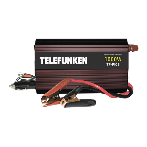
Telefunken
Telefunken TF-PI03 instruction manual
Rayleigh Instruments
Rayleigh Instruments RI-ENERGYFLOW-MODULAR Series Quick start installation guide
NSM
NSM M 132 Use and maintenance manual
Wagan
Wagan Elite 700W PRO user manual
Haier
Haier SUPER MATCH AS35S2SF1FA-BC Service manual
YASKAWA
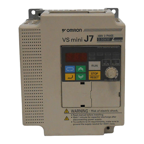
YASKAWA VS MINI J7 series instruction manual
