Chippmann CS-8 VCF1E User manual

CS-8 Series
Owners' manual VCF1E


CS-8 Series VCF1E Rev1.2, Feb. 2018
-1-
User manual by Carsten Schippmann
raphic design CS-8 Series: Carsten Schippmann
Concept and development: Carsten Schippmann
English translation by Carsten Schippmann
Contact:
Schippmann electronic musical instruments
Dipl.-Ing. Carsten Schippmann
Wartburgstr. 8
D-10823 Berlin
Web: www.schippmann-music.com
Email: info@schippmann-music.com
The manufacturer
Schippmann electronic musical instruments
is constantly
striving for improvements and developments of their products. Therefore, we
reserve the right to change technical specifications which improve our
products at any time without notice. This includes the look of the unit which
might differ from pictures in this manual.
No part of this publication is to be reproduced, transmitted, transcribed or
translated in any form or by any means whatsoever without written
permission by
Schippmann electronic musical instruments
.
2017, Schippmann electronic musical instruments, errors excepted, subject
to change without prior notice.

CS-8 Series VCF1E Rev1.2, Feb. 2018
-2-
PREFACE
First of all, congratulations on the purchase of this 3U Eurorack synthesizer
module. This manual contains a condensed description of the functionality
and addresses users with a certain level of elementary technical knowledge.
The CS-8 VCF1E is a very versatile, fully analogue, programmable and voltage-
controlled filter (VCF). It is capable of processing all sorts of audio signals. It is
designed for mounting into a 3U Eurorack with an internal +/- 12V power
supply.
Basically, two modes are possible. The classical filter mode with 12
selectable different functions (low-, high,- band-passes) and the haser
mode with also 12 haser-sounding combining modes (4x phaser-, 2x low-,
2x high,- 4x band-passes).
For the classic filter mode 3 different resonance modes are available, where
each of these generate for each filter function again different sound
impressions. So, there is no rule how to sound a certain selected resonance
mode. It depends on the selected function.
With a further 4-pos. rotary switch the resonance em hasize is dialable,
which provides further sound nuances. This is also equipollent to the
amplitude of the self-oscillation. An illuminated tactile switch allows to add a
unique 2nd harmonic distortion to the resonance sound.
The frequency range (cutoff) goes from 2 Hz to 40 kHz. A gain controller allows
input-to-output gains from -20 db to 0 db. A clip LED light up just before
output clipping.
Design and implementation meet highest technical standards concerning
usability, sound quality, and signal-to-noise ratio. The front panel is made from
powdered and printed piece of aluminium sheet metal of 2 mm gauge. The
entire design and production work was done in ermany.
Made in ermany
CS-8 Series VCF1E Rev1.2, Feb. 2018
-3-
1. WARRANTY .........................................................................................................................4
1.1 Limited Warranty ....................................................................................................4
1.2 Terms of Warranty ..................................................................................................4
1.3 Warranty transferability ......................................................................................4
1.4 Claim for damages ..................................................................................................4
2. CE AND FCC COMPLIANCE STATEMENTS ...............................................................5
3. DISPOSAL ............................................................................................................................5
4. SAFETY INSTRUCTIONS .................................................................................................6
5. MAINTAINANCE/ CLEANING ........................................................................................7
6. GETTING STARTET............................................................................................................7
6.1 Un acking ..................................................................................................................7
6.2 Installation .................................................................................................................7
7. CONTROLS ...........................................................................................................................8
7.1 Front anel .................................................................................................................8
7.2 Back ............................................................................................................................ 10
7.3 Initial o eration .................................................................................................... 12
8. MODULE DESCRIPTION ............................................................................................... 12
Structure .......................................................................................................................... 12
In ut .................................................................................................................................. 13
Frequency ....................................................................................................................... 13
Resonance ....................................................................................................................... 13
Resonance-Em hasize ............................................................................................... 14
Resonance-mode ......................................................................................................... 15
Filter function ................................................................................................................ 16
2nd Harm ......................................................................................................................... 25
Out ut .............................................................................................................................. 25
9. TECHNICAL DATA AND SIGNAL VALUES ............................................................. 26
9.1 Technical Data (in general) .............................................................................. 26
9.2 Signals and ratings .............................................................................................. 26

CS-8 Series VCF1E Rev1.2, Feb. 2018
-4-
1. WARRANTY
1.1 Limited Warranty
Schippmann electronic musical instruments
warrants the mechanical and
electronic components of this product for a period of two (2) years from the
original date of purchase, according to the warranty regulations described
below. If the product exhibits any faults within the specified warranty period
that are not excluded from this warranty,
Schippmann electronic musical
instruments
shall, at its discretion, either replace or repair the product. This
warranty exists in addition to the general terms of business of the
manufacturer
Schippmann electronic musical instruments
.
1.2 Terms of Warranty
Schippmann electronic musical instruments
reserves the right to execute
warranty services only if the product comes with a copy of the dealer’s original
invoice. Final discretion of warranty coverage lies solely with
Schippmann
electronic musical instruments
. Any
Schippmann electronic musical
instruments
product deemed eligible for repair or replacement under the
terms of this warranty will be repaired or replaced within 30 days after
receiving the product at
Schippmann electronic musical instruments
.
Damages or defects caused by improper handling or opening of the unit by
unauthorized personnel (user included) are not covered by this warranty.
Products which do not meet the terms of this warranty will be repaired
exclusively at the buyer´s expense and returned C.O.D. with an invoice for
labour, materials, return shipping, and insurance. Products repaired under
warranty will be returned with shipping prepaid by
Schippmann electronic
musical instruments
. Outside Germany, roducts will be returned at the
buyer´s ex ense.
1.3 Warranty transferability
This warranty is extended to the original purchaser and cannot be transferred.
No other person (retail dealer, etc) shall be entitled to give any warranty
promise on behalf of
Schippmann electronic musical instruments
.
1.4 Claim for damages

CS-8 Series VCF1E Rev1.2, Feb. 2018
-5-
Schippmann electronic musical instruments
does not accept claims for
damages of any kind, especially consequential loss or damage, direct or
indirect of any kind however caused. Liability is limited to the value of this
product. The general terms of business drawn up by
Schippmann electronic
musical instruments
apply at all times.
Please note: The controls and switches, especially the Freq (cutoff-
frequency) or others are programming facilities, no real-time controllers!
Tweak them carefully since we cannot be held liable for “abused”
potentiometers and switches.
2. CE AND FCC COMPLIANCE STATEMENTS
This device has been tested and deemed to comply with the DIN EN 60065
standards.
This device has been tested and deemed to comply with the requirements,
listed in FCC Regulations, part 15. The device complies with EN 55103-1 and
EN 55103-2 standards.
Because of the entirely analogue construction, this device does not generate
radio frequencies and will not interfere with radio frequencies generated by
other electronic devices.
3. DISPOSAL
This device has been manufactured to RoHS-standards, in compliance with the
requirements of the European parliament and council and is thus free of lead,
mercury, and cadmium.
!! Notice: This roduct is still s ecial waste and is not to be dis osed of
through regular household waste !!
For dis osal, lease contact your local dealer or Schippmann electronic
musical instruments

CS-8 Series VCF1E Rev1.2, Feb. 2018
-6-
4. SAFETY INSTRUCTIONS
BEFORE USING THIS PRODUCT FOR THE FIRST TIME, PLEASE READ THE
ENTIRE USER MANUAL THOROUGHLY.
•PLEASE AVOID SHARP BENDIN OF ANY CORDS AND CABLES.
•CORDS SHOULD NOT BE INSTALLED WITHIN THE REACH OF CHILDREN
OR PETS.
•DO NOT TREAD THE ENCLOSURE OF THE PRODUCT, DO NOT PLACE
HEAVY OBJECTS ON IT.
•BEFORE REMOVIN THE PRODUCT FROM THE RACK, PLEASE
DISCONNECT THE POWER PLU AND ALL OTHER CABLE
CONNECTIONS.
•PLEASE DISCONNECT THE POWER PLU FROM THE OUTLET IN CASE OF
A THUNDERSTORM.
•NEVER OPEN THE ENCLOSURE OF THE PRODUCT! NEVER TRY TO
MODIFY THE INTERNAL CIRCUITRY! ONLY QUALIFIED SERVICE
PERSONNEL IS ALLOWED TO OPEN THE ENCLOSURE.
•DO NOT PLACE OPEN FIRE ON TOP OF THE PRODUCT (CANDLES, ASH
TRAYS, HOT THAI CURRIES ETC).
•NEVER EXPOSE THE PRODUCT TO WATER, BEER, OR MOISTURE.
•ADULTS ARE TO MAKE SURE THAT CHILDREN FOLLOW ALL SAFETY
INSTRUCTIONS. SAME THIN OES FOR PETS.
•AVOID MECHANICAL STRESS OR IMPACT. DO NOT DROP THE PRODUCT;
EVEN IF THERE IS A CONTROL LABELLED "DROP"!.
•DO NOT USE THE PRODUCT WITH TOO MANY OTHER ELECTRONIC
DEVICES RUNNIN FROM ONE SIN LE OUTLET, ESPECIALLY IN
CONNECTION WITH EXTENSION CORDS. DO NOT ATTEMPT TO SAVE
MONEY ON CHEAP SOLUTIONS. BUY PROPER HI H-DUTY POWER
DISTRIBUTORS AND CORDS!
•NEVER USE EXTENSION CORDS WITH LESS MAXIMUM LOAD THAN THE
TOTAL POWER CONSUMPTION OF ALL DEVICES CONNECTED TO A
SIN LE POWER OUTLET COMBINED. OVERLOADIN EXTENSION CORDS
CAN CAUSE FIRE.
•AVOID MECHANICAL STRESS ON ACKS AND KNOBS / SWITCHES.
•PROTECT YOUR SPEAKERS AND EARS (!) AGAINST EXCESSIVE AUDIO
LEVELS. THE CS-8 VCF1E UNIT IS CAPABLE OF GENERATING

CS-8 Series VCF1E Rev1.2, Feb. 2018
-7-
EXTREMELY LOW AS WELL AS EXTREMELY HIGH FREQUENCIES. BOTH
MIGHT CAUSE SERIOUS DAMAGE TO AUDIO EQUIPMENT AND EAR-
DRUMS!
5. MAINTAINANCE/ CLEANING
•BEFORE CLEANIN THE PRODUCT, PLEASE DISCONNECT THE POWER
PLU FROM THE OUTLET OR DISCONNECT THE MODULE FROM ITS
POWER CONNECTOR BY PULLIN THE FLAT RIBBON CABLE.
•USE A DRY OR SLI HTLY MOIST CLOTH OR COMPRESSED AIR FOR
CLEANIN . NEVER USE ANY CLEANER OR THINNER (E. . PAINT THINNER
OR ACETON). PRINTS AND PAINTWORK WILL IMEDIATELY BE
DESTROYED!! ALSO AVOID ALCOHOL (ISOPROPYLIC), AS, SPIRITS
(SCOTCH SIN LE MALTS, FOR A START) OR ABRASIVE HOUSEHOLD
CLEANERS!
6. GETTING STARTET
6.1 Un acking
The box should contain the following items:
- 1 x CS-8 Series VCF1E 3HU rack-mount module
- 1 x Ribbon cable (20 cm length with two 16 pole IDC-connectors)
- 4 x M3 screws
- 4 x polypropylene washers
- this owners’ manual
If the content of the box turns out to be incomplete, please get in touch with
your dealer or
Schippmann electronic musical instruments
immediately. In
case of damage caused in transit, please get back to the responsible carrier
and
Schippmann electronic musical instruments
immediately. We will support
you in this case.
6.2 Installation
Place the unit on a clean, dry and sturdy surface, or use a suitable keyboard
stand or 19” rack. For 19” rack mounting, a suitable rack (3U Eurorack with +/-

CS-8 Series VCF1E Rev1.2, Feb. 2018
-8-
12V power supply rails) is required. The CS-8 VCF1E uses discrete all-analogue
electronics. Thus certain parameters as Freq and other may be temperature-
sensitive. We recommend placing the CS-08 VCF1E away from heat sources
such as radiators, lamps or other units that produce heat (e.g. power amps or
internal power supplies).
7. CONTROLS
7.1 Front anel
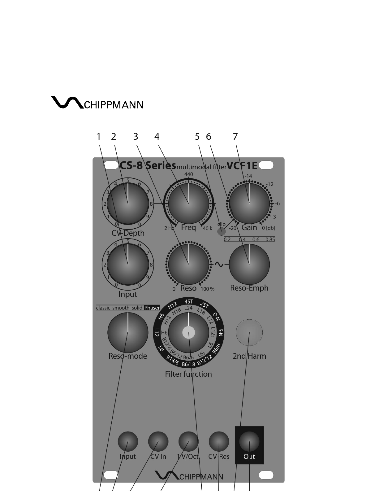
Fig. 1 shows the front panel with consecutively numbered controls and jacks.
CS-8 Series VCF1E Rev1.2, Feb. 2018
-9-
Fig. 1

CS-8 Series VCF1E Rev1.2, Feb. 2018
-10-
1. In ut Controller – attenuates the incoming audio signal at
jack 9
between 0 and 1
2. CV-De th Controller – attenuates the frequency control voltage at
jack
10
between 0 and 1
3. Reso Controller – set the resonance of the filters between 0 and self-
oscillation
4. Freq Controller – set the resonance frequency of the filters between ca. 2
Hz and 40 kHz (0.8 Hz to 100 kHz at mode "Phaser")
5. cli LED – illuminates "red" just before clipping of the audio output stage
6. Reso-Em h 4-pos. rotary switch – determines the strength of the
emphasize of the resonance or the amplitude of the self-oscillation (0.2 =
weak to 0.85 = strong)
7. Gain Controller – set the signal gain from
jack 9
to
jack15
(at position
"10" of Cont.
1)
between -20 db and 0 db
8. Reso-mode 4-pos. rotary switch – selects one of three resonance modes
and switches the filter to the Phaser mode
9. In ut jack (input) – routes the applied signal via
Cont. 1
to the filter input
10. CV In jack (input) – routes the applied signal via
Cont. 2
to the frequency
modulation input of the filters
11. 1V/Oct jack (input) – an applied voltage shifts the resonance frequency
of the filter by ± one octave with every ± one Volt input voltage
12. Filter function 12-pos. rotary switch (double assigned)– selects one of 12
different filter functions
13. CV-Res jack (input) – control of the resonance; a voltage of +5 V at this
input corresponds the position "10" of the Cont.
3
, negative input
voltages are allowed
14. 2nd Harm illuminated pushbutton – switch with alternating function
activates a distortion, which adds even-numbered harmonics, especially
to the resonance; "red" inactive, "green" active
15. Out jack (output) – provides the filter output signal
7.2 Back
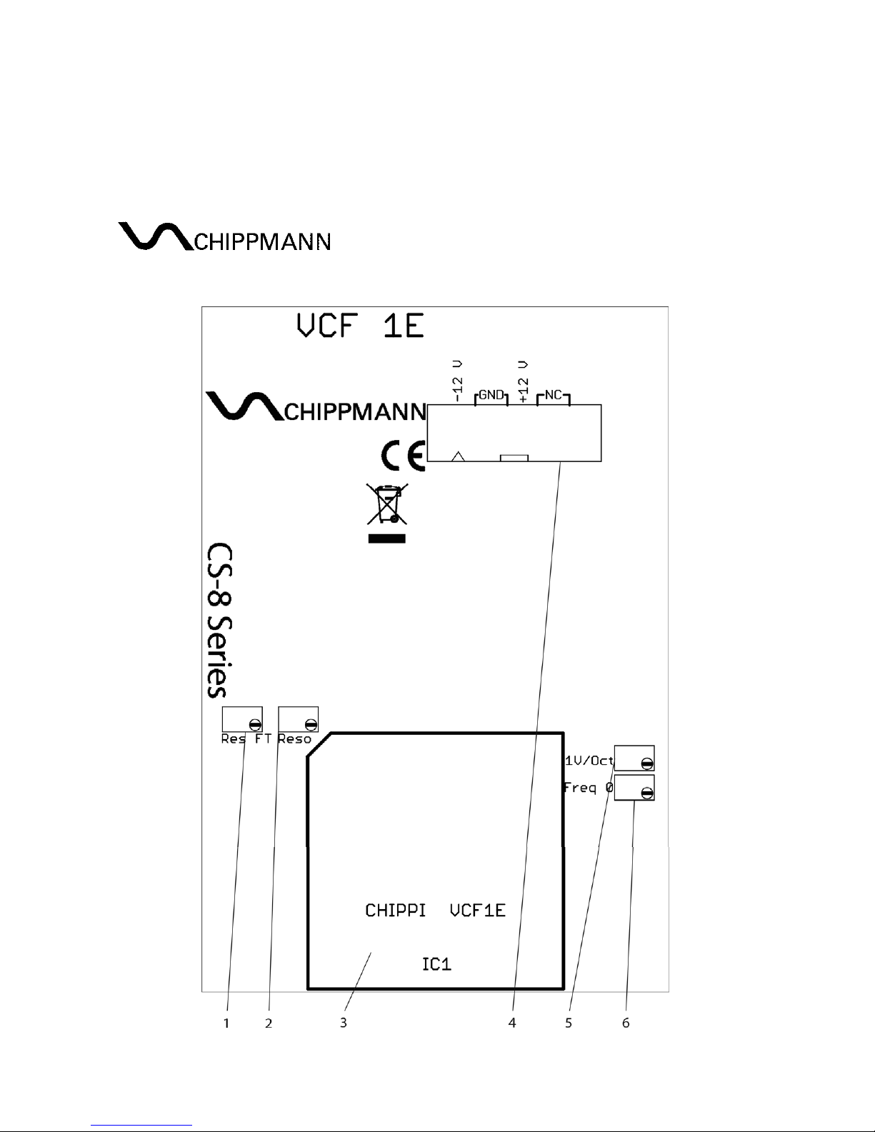
Fig. 2 shows the back of the module with consecutively numbered elements.
CS-8 Series VCF1E Rev1.2, Feb. 2018
-11-
Fig. 2
1. Res FT 12-gauge-trimmer – Resonance control-feed-through
2. Reso 12-gauge-trimmer – starting point of resonance
3. IC1 – pinned filtercore modul
4. 16 Pin ower su ly box-header
5. 1V/Oct 12-gauge-trimmer – sensitivity at jack
11
6. Freq 0 12-gauge-trimmer – offset resonance frequency
CS-8 Series VCF1E Rev1.2, Feb. 2018
-12-
7.3 Initial o eration
The power connector’s (4) pin-out in top view (refer to fig. 2) is assigned as
follows:
Bottom to top, left to right. Thus pin 1 is located at bottom left, pin 2 above pin
1 etc. Pin 15 is at bottom right, pin 16 at top right.
Pin 1, 2 = -12 V (labelled with a triangle)
Pin 3-8 = ND (ground, 0 V), located outward on all jacks
Pin 9, 10 = +12 V
Pin 11-16 = not in use
To hook up power to the module, connect one of the IDC-jacks of the included
flat ribbon cable to the connector (refer to fig. 2). Observe guide key for the
polarity of the connector in order to avoid pin reversal. The red tag of the
cable is to match the triangle-label.
8. MODULE DESCRIPTION
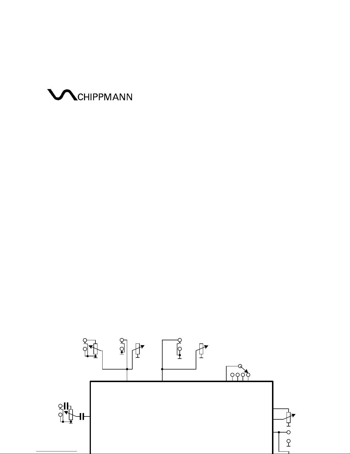
Structure
Audio out
VCF
ain
Out
Audio In
CV In 1 V/Oct
FREQ
Freq Reso
CV-Res
RESO
Reso-Emph
0.2
clip
(red)
classic
Reso-mode
functions 1-12
Filter function
Input
0.4 0.6 0.85
smooth
solid
Phaser
Input
CV-Depth
Fig. 3

CS-8 Series VCF1E Rev1.2, Feb. 2018
-13-
Fig. 3 shows the structure of the filter. In the following piece by piece every
parts will be described and as the case may be exemplified with graphics.
In ut
This section includes the jack 9 (Input) and the controller 1 (Input). The input
signal to be processed by the VCF1E flows from
jack 9,
capacitively decoupled,
to the
Cont. 1
where it is attenuated between 0 (-∞ db) and 1 (0 db). To obtain
a signal gain of 1 (without resonance) at the signal output
Out
(at
ain
= 0 db),
the
Cont. 1
has to be set to full CW.
Hint: This filter is, btw. as all CS-8 filters, constructed in that way, that it shows
lowest harmonic distortions and cleanest sound at studio level input (0.775
V
RMS
or ca. 1-2 V
pp
). The input amplitude has a BI influence of the sound, the
resonance and the dynamic behavior of the filter.
Frequency
This section includes the controller 4 (Freq), the jack 10 (CV In), 11 (1V/Oct.)
and the controller 2 (CV-Depth). Frequency means that one, where the filter at
high resonance (see below) oscillates with. At same time this is the frequency
where the roll-off starts at low-, or high-passes or center-frequency for band-
passes, resp.. The controller Freq allows a range from 2 Hz to 40 kHz. A control
voltage (CV) at jack 10 will be attenuated between 0 - 1 via the controller CV-
Depth. At full CW the sensitivity is about 1.9 octaves/Volt. A CV at jack 10 is
weighted with 1 octave/Volt. This input is calibrated.
Hint: In phaser mode (s. below) are existing two resonance frequencies, which
are located left and right from the roll-off frequency in the classical filter mode.
Resonance
This includes the controller 3 (Reso) and the jack 13 (CV-Res). The resonance
is the self-resonance of the filter which comes into being when the filter
output will be feed back to the filter input in a controlled way. The tendency to
self-oscillation rises up from left to right of the controller Reso starting from
none to self-oscillation at about 3 o'clock (sine symbol). A CV from 0 V to +5 V
at jack 13 causes the same effect as the controller Reso from left to right. At +4
V (
Reso
-position = 0) the filter starts to oscillate. Input signals will be amplified
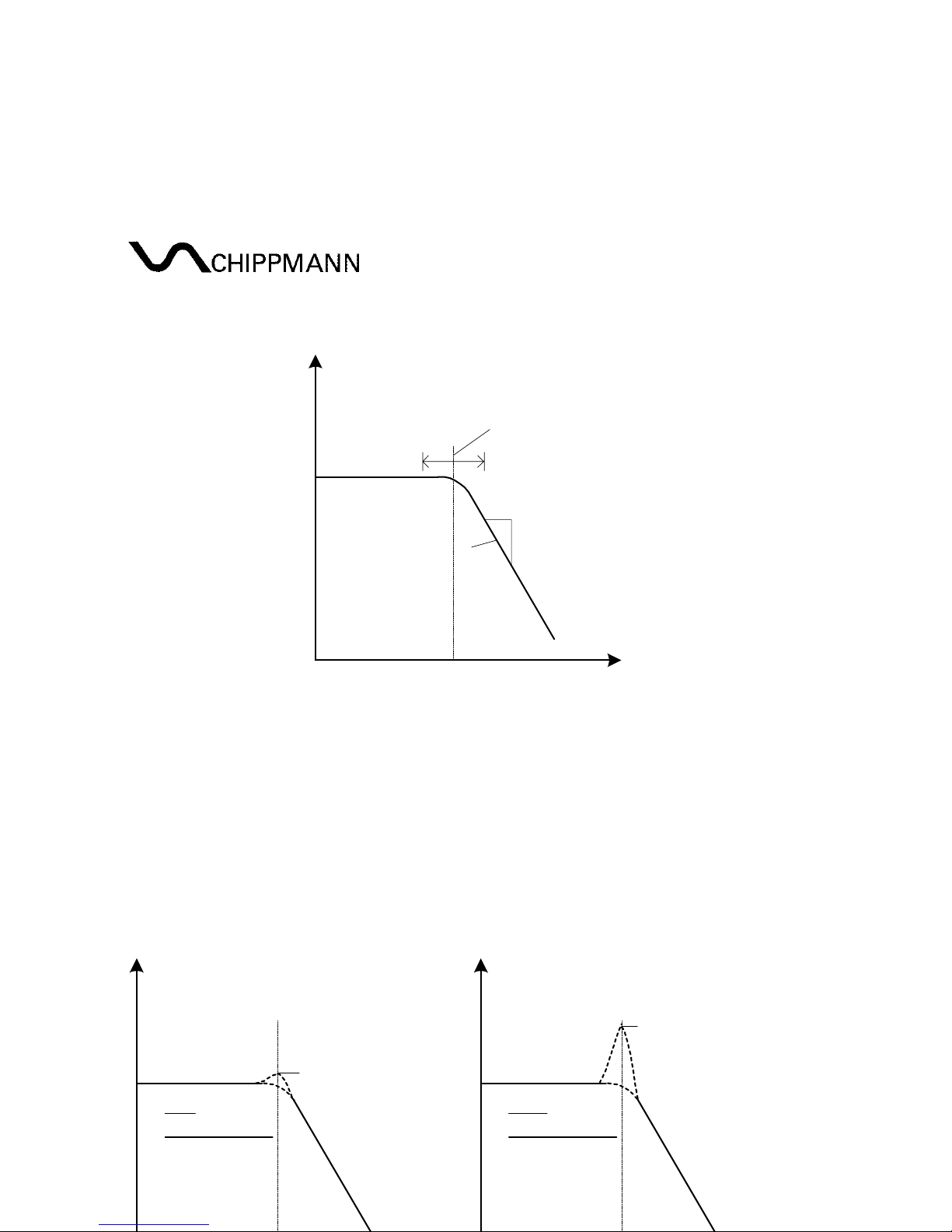
around the resonance frequency as illustrated in Fig. 4.
CS-8 Series VCF1E Rev1.2, Feb. 2018
-14-
Level [dB]
Resonance frequency /
cutoff-freq. (fc)
Low ass-
Function
∆
dB
∆
freq.
Slope
[db/Octave]
Signal frequency
Fig. 4
Resonance-Em hasize
With the 4-Position-rotary switch 6 (Reso-Emph) the emphasize of the
resonance or amplitude of self-oscillation, resp., can be selected. This is
expressed in numbers 0.2, 0.4, 0.6 and 0.85, where higher values mean more
emphasize. Fig. 5 gives an illustration.
Level [dB]
fc
Low ass-
Function
Signal frequency
start of
self-oscillation
low
Emph-values
Level [dB]
fc
Low ass-
Function
Signal frequency
high
Emph-values
start of
self-oscillation
Fig. 5
CS-8 Series VCF1E Rev1.2, Feb. 2018
-15-
Resonance-mode
With the 4-Position-rotary switch 8 (Reso-mode) different ways of feed backs
are selectable leading to different sound characters. Firstly, the three modes
"classic", "smooth" and "solid" shall be described. These three modes refer to
the filter operation (inner scale of "
Filter function
").
classic:
This is the typical feedback mode commonly used in almost all 4-pole
filter designs. For low-passes arises a so-called "drop" in the pass-band without
any adopted measures, which means a signal gain drop of about -14 db as
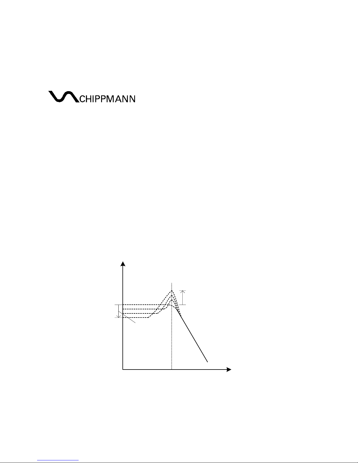
shown in Fig. 6. The dro here for the six selectable low-pass functions is
adjusted to about -2.1 db. The other functions are not affected by this effect.
Level [dB]
fc
Resonance
drop /
gain loss
Signal frequency
Low ass-
Function
Fig. 6
smooth, solid:
These are two further ways of feedback, offered by this filter
design. Actually, there is no rule which describes homogeneous the sound
character for all filter functions. Meaning, the "solid" mode for the 24 db low-
pass could sound very smooth and restrained whereas it could sound in a
high-pass mode very loud and rigorous. So, all filter functions are to compare
with each resonance modes to find out the character. A drop doesn't exist in
these modes.
Phaser:
In this mode the complete filter will be switched into a real 4-stage-
Phaser, meaning the total structure is no longer that one of a 4-pole-filter. For
this mode the outer scale of the switch "
Filter function
" indicates the

CS-8 Series VCF1E Rev1.2, Feb. 2018
-16-
selectable functions. As mentioned above two resonance peaks will be formed
in phaser operation, meaning there are two frequencies where the phaser with
increase of resonance tend to oscillate, shown further below.
Filter function
The double assigned 12-pos.-rotary switch (12) allows the selection of 12
different functions.
Filter operation (
classic, smooth, solid
) - inner scale:
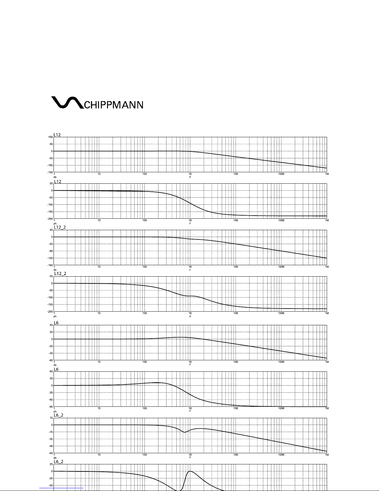
L24: 24 db low-pass
L18: 18 db low-pass
L12: 12 db low-pass
L12
2
: 12 db low-pass
L6: 6 db low-pass
L6
2
: 6 db low-pass
B6/6: 6 db / 6 db band-pass
B6/12: 6 db / 12 db band-pass
B12/6: 12 db / 6 db band-pass
H6: 6 db high-pass
H12: 12 db high-pass
H18: 18 db high-pass
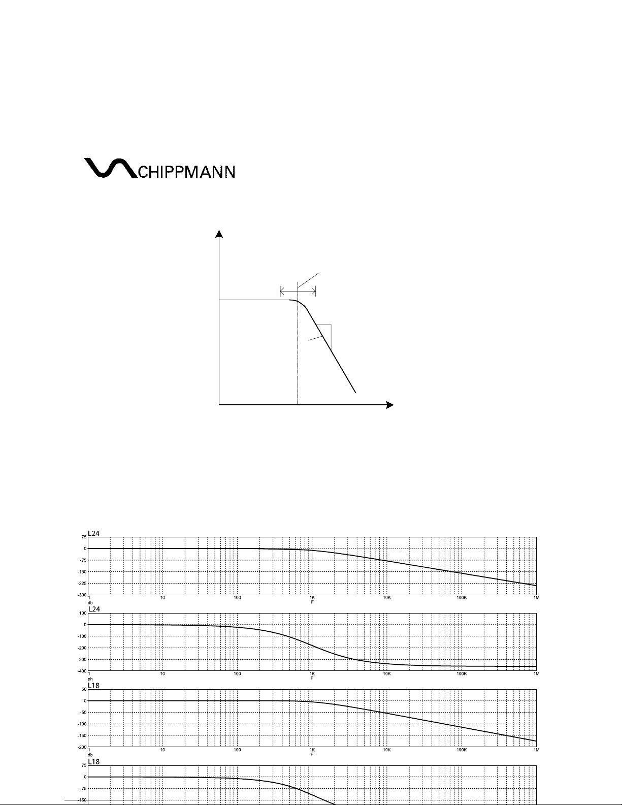
The decibel values mean the slope of the roll-off range, commonly denoted in
db per octave. For simplifying "octave" is omitted, because for typical filters
the values implies that db/octave is meant. Fig. 7 shows this exemplarily for a
low-pass. For band-passes two roll-off ranges exists, one with high-pass
character before and one with low-pass character behind the center
frequency.
CS-8 Series VCF1E Rev1.2, Feb. 2018
-17-
Level [dB]
Resonance frequency /
cutoff-freq. (fc)
Low ass-
Function
∆
dB
∆
freq.
Slope
[db/Octave]
Signal frequency
Fig. 7
Next follows a graphic illustration in Fig. 8 of all 12 filter functions and relating
phase response (none resonance) in the order as above. The resonance
frequency is always 1 kHz.
CS-8 Series VCF1E Rev1.2, Feb. 2018
-18-
Table of contents
Popular Water Filtration System manuals by other brands


resideo
resideo Braukmann F76S installation instructions

Autotrol
Autotrol LOGIX 255/740 Operation manual

GE
GE GNUT03B Owner's manual and installation

Clean Water Systems
Clean Water Systems 5900-BT Tannin Filter Installation & maintenance guide

Eureka Forbes
Eureka Forbes Aqua Guard RO user guide

Pall
Pall UR620 Series Service instructions


