Xtreme Power 90160 Original instruction manual

SALT WATER SYSTEM CHLORINATOR
SAVE THIS MANUAL: KEEP THIS MANUAL FOR SAFETY WARNINGS, PRECAUTIONS, ASSEMBLY,
OPERATING, INSPECTION, MAINTENANCE AND CLEANING PROCEDURES. WRITE THE PRODUCT’S
SERIAL NUMBER ON THE BACK OF THE MANUAL NEAR THE ASSEMBLY DIAGRAM (OR MONTH
AND YEAR OF PURCHASE IF PRODUCT HAS NO NUMBER)
OWNER’S MANUAL AND SAFETY INSTRUCTIONS
ITEM: 90160 / 90161 / 90162
FOR QUESTIONS PLEASE CALL OUR CUSTOMER SUPPORT: 909.628.0880 MON-FRI 9AM TO 3PM PST

IMPORTANT SAFETY INFORMATION
SAFETY
The warnings, precautions, and instructions discussed in this instruction manual cannot cover all possible
conditions and situations that may occur. It must be understood by the operator that common sense and
caution are factors which cannot be built into this product, but must be supplied by the operator. Read
carefully and understand all ASSEMBLY AND OPERATION INSTRUCTIONS before operating. Failure to
follow the safety rules and other basic safety precautions may result in serious personal injury.
1
Please note, the total working hours for the T-Cell should be less than 8 hours total per day. If you are
using a variable speed pump for 24 hours a day be sure to adjust the chlorine output to 25-30%. If the
pump is only running 10 hours per day adjust the chlorine output between 60-80%.
You can use this calculation to calculate the appropriate chlorine output for your pool, suggest
at 6 hours per day:
Pump running 24 (Hours a day)*25% (Chlorine Output)= 6hr (cell run time per day at 25%).
Pump running 20 (Hours a day)*30% (Chlorine Output)= 6hr (cell run time per day at 30%).
Pump running 15 (Hours a day)*40% (Chlorine Output)= 6hr (cell run time per day at 40%).
Pump running 12 (Hours a day)*50% (Chlorine Output)= 6hr (cell run time per day at 50%).
Pump running 8 (Hours a day)*75% (Chlorine Output)= 6hr (cell run time per day at 75%).
Congratulations on your purchase of a new T Series Replacement Cell! Our cells are designed to meet
or exceed original specications, for optimal performance and reliability. T-Cell-3 and T-Cell-9 require
software r1.5 for AquaRite or 4.2 for AquaLogic or newer to be compatible. These revisions started in 2009,
meant for use in Hayward Goldline AquaRite, Aqua Logic and Pro Logic salt systems. T-Cell-15 requires
software r1.50 for AquaRite or 4.2 for AquaLogic or newer to be compatible. These revisions started in
2009, meant for use in Hayward Goldline AquaRite, AquaLogic, Pro Logic, SwimPure, Mineral Springs.
IMPORTANT: Always make sure the input power is completely disconnected and all pool equipment is shut
off before attempting any service procedures. All service should be performed by a qualied professional.
Remove the old Cell from the plumbing by loosening the threaded collars on both ends of the Cell.
Disconnect the Cell Cord from the control panel.
Inspect the O-Rings on the plumbing unions. If damaged or worn, replace before installing the new Cell.
Position the new T series Replacement Cell between the plumbing unions. Tighten the two threaded
collars by hand for a water-tight seal, do not over-tighten. Plug the Cell Cord into the control panel.
Once power is restored to the control panel (concurrently with the pump and lter), the system can now
be operated as instructed in the original manufacturer’s product manual.
INSTALLATION

OPERATION
3
How to replace CFT
Step 1. Turn off the power to the pump and
chlorine salt generator. Ideally this should be
done at the circuit breaker. The controller display
should go blank.
Step 2. Relieve the water pressure at the relief valve,
it is usually on top of your pool lter.
Step 3. Unscrew the threads on both sides of
the original T cell.
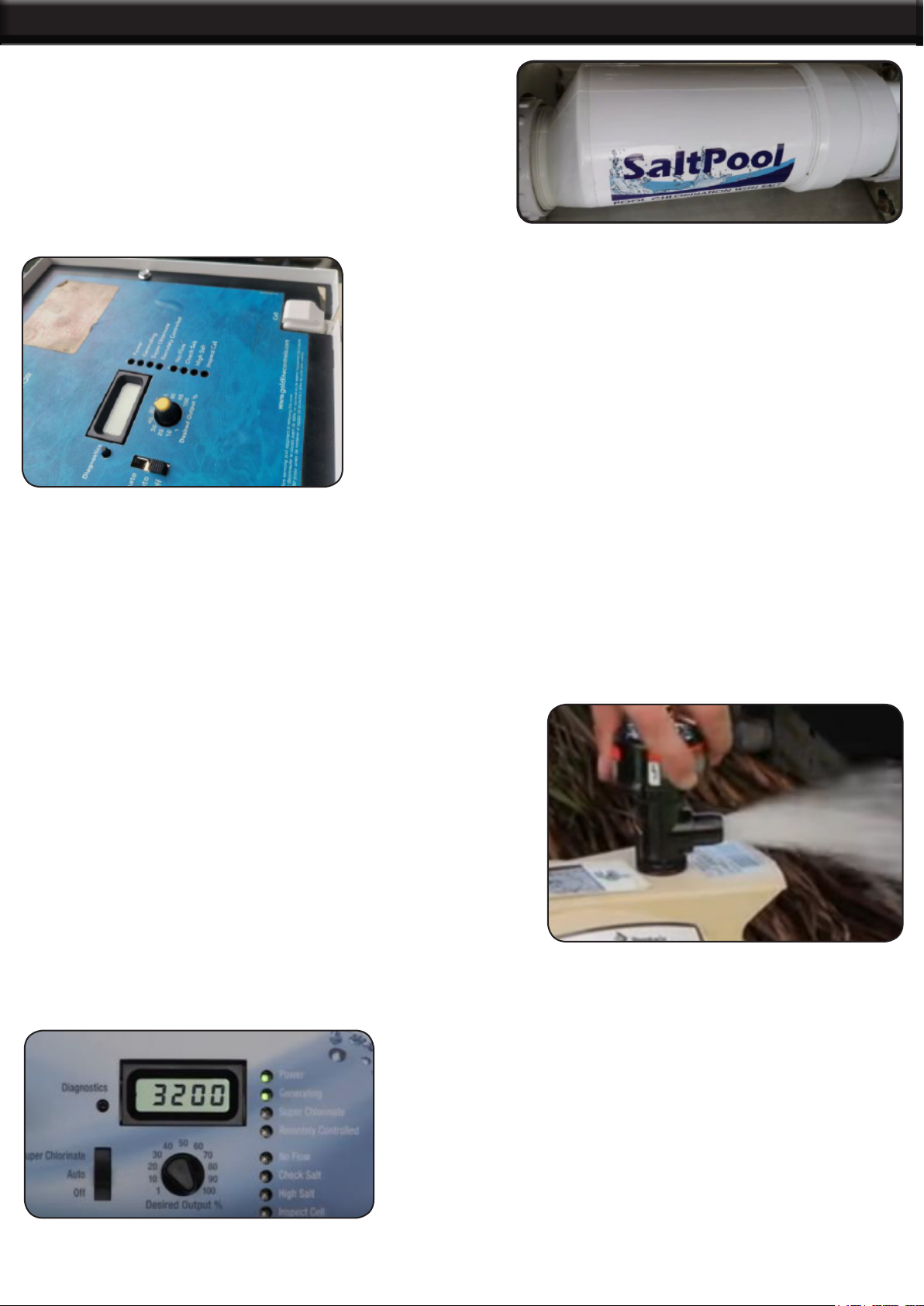
Step 4. Original AquaRite Turbo Cell out from the
piping.
Step 5. Pull the plug out at the lower corner
of the digital controller.
Step 6. Inspect the O-rings inside the union
connected with the pipe for any wear and replace
them if possible. Apply a thin layer of lubricant to the
O-ring.
OPERATION
11
Step 7. Place the CFT cell into the piping and
screw the unions back onto the ends of the
new cell. Tighten the thread. The cell can be
positioned either way. In fact, we suggest to
reverse the cell every time you clean it to extend
the life of the cell.
Step 8. Plug the power cord into the lower corner of
the controller.
Step 9. Restart the pool pump and salt chlorine generator. The controller should light up and
the pool pump should operate.
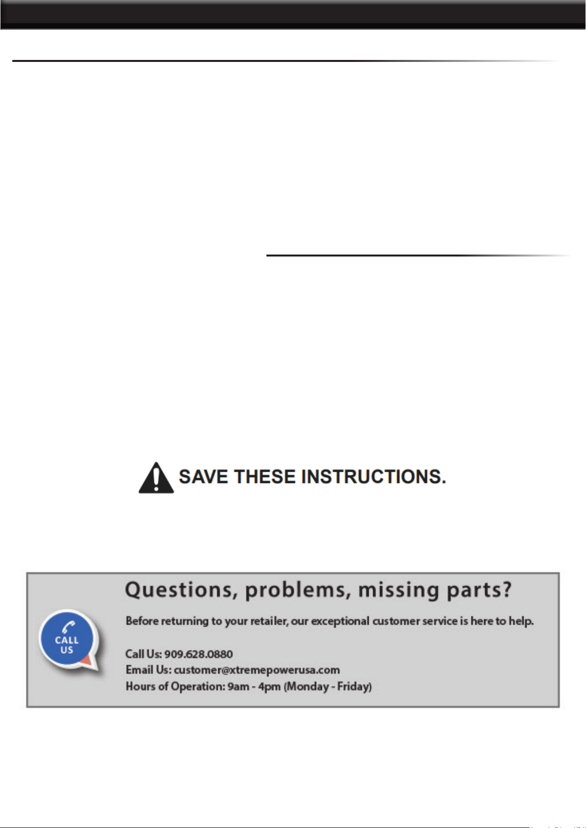
Step 10. Any air in the duct should be drained from
the open safety valve. When the water begins to
squirt from the safety valve, close the valve.
Step 11. After a couple of minutes, the controller
display will show a salt value of between 2700 and
3400 and the “Power” and “Generating” LEDs should
be light on.

PARTS LIST
12
1: THREAD
2: FLOW SWITCH
TROUBLESHOOTING
4

TROUBLESHOOTING
5
Polaris-Attach wires to proper screw terminals as shown below. Note that screw terminal “1” is marked on the
Polaris PCB.
TROUBLESHOOTING
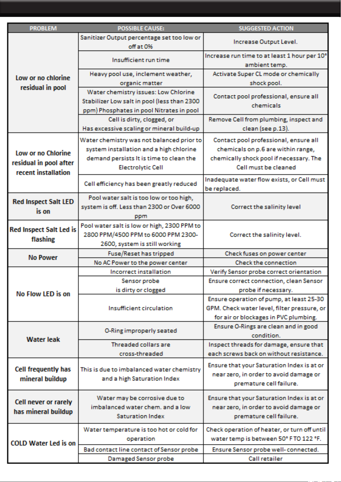
Diagnostic Displays
Sequential pushes of the small “diagnostic” button next to the LCD display will cause the SPS to display the
following information:
1. Pool temperature (xx degrees Fahrenheit or Celsius)
2. Cell voltage (typically 21.0 to 27.0 volts when chlorine is being generated, otherwise 16-25V)
3. Cell current (typically 2.50 to 7.80 amps when chlorine is being generated, otherwise 0 amps)
4. Desired Output % (“0P” -- “100P” depending on knob position controller)
5. Instant salinity ( -xxxx ppm or -x.xx grams/Liter)
6. Product name sent to the pool automation control display
7. Software revision level
8. Cell type.
On the 8th push of the button the display will revert back to the default salt display. Also if the button is not
pushed for 30 seconds, the display will revert back default salt.
Diagnostic Displays
“Power” LED not on:
Check to make sure 120 / 240 VAC input power is connected to the control. Be sure the jumpers are set
properly. Verify input voltage with a voltmeter. If there is input power, the fuse may have blown. The board is
protected by a 20 amp mini ATO fuse located on the circuit board above the cell connector.
“Generating” LED ashing:
The temperature of the pool water is too high or low to operate. You can override this by switching the main
switch to SUPER CHLORINATE. The SPS will run at maximum output for the remainder of the current pump
cycle or 24 hours, whichever comes rst.
6
OF NOTE
THE MANUFACTURER AND/OR DISTRIBUTOR HAS PROVIDED THE PARTS LIST AND ASSEMBLY
DIAGRAM IN THIS MANUAL AS A REFERENCE TOOL ONLY. NEITHER THE MANUFACTURER OR
DISTRIBUTOR MAKES ANY REPRESENTATION OR WARRANTY OF ANY KIND TO THE BUYER THAT
HE OR SHE IS QUALIFIED TO MAKE ANY REPAIRS TO THE PRODUCT, OR THAT HE OR SHE IS
QUALIFIED TO REPLACE ANY PARTS OF THE PRODUCT. IN FACT, THE MANUFACTURER AND/OR
DISTRIBUTOR EXPRESSLY STATES THAT ALL REPAIRS AND PARTS REPLACEMENTS SHOULD BE
UNDERTAKEN BY CERTIFIED AND LICENSED TECHNICIANS, AND NOT BY THE BUYER. THE BUYER
ASSUMES ALL RISK AND LIABILITY ARISING OUT OF HIS OR HER REPAIRS TO THE ORIGINAL
PRODUCT OR REPLACEMENT PARTS THERETO, OR ARISING OUT OF HIS OR HER INSTALLATION
OF REPLACEMENT PARTS THERETO.
Record Product’s Serial Number Here:
Note: If product has no serial number, record month and year of purchase instead.
Note: Some parts are listed and shown for illustration purposes only and are not available individually
as replacement parts.
PLEASE READ THE FOLLOWING CAREFULLY
PRODUCT MADE IN CHINA
This manual suits for next models
2
Table of contents
Other Xtreme Power Water Filtration System manuals


Popular Water Filtration System manuals by other brands


Topper
Topper WOW RO 50 Installation & user manual

puraDYN
puraDYN Millennium Technology Series Standard Installation Manual

Honeywell
Honeywell HF49 installation instructions

Reverse Osmosis
Reverse Osmosis Genesis installation manual

Emerald
Emerald HOME 20 OFFICE B DEVICE operating manual

Reef Pure RO Systems
Reef Pure RO Systems 6 Stage 400GPD Expert user manual