July 2018
443580508481
Signify North America Corporation
200 Franklin Square Drive
Somerset, NJ 08873, USA
Phone: 855-486-2216
www.chloride-lighting.com
Signify Canada Ltd./Signify Canada Ltée.
281 Hillmount Road,
Markham, ON, Canada L6C 2S3
Phone: 800-668-9008
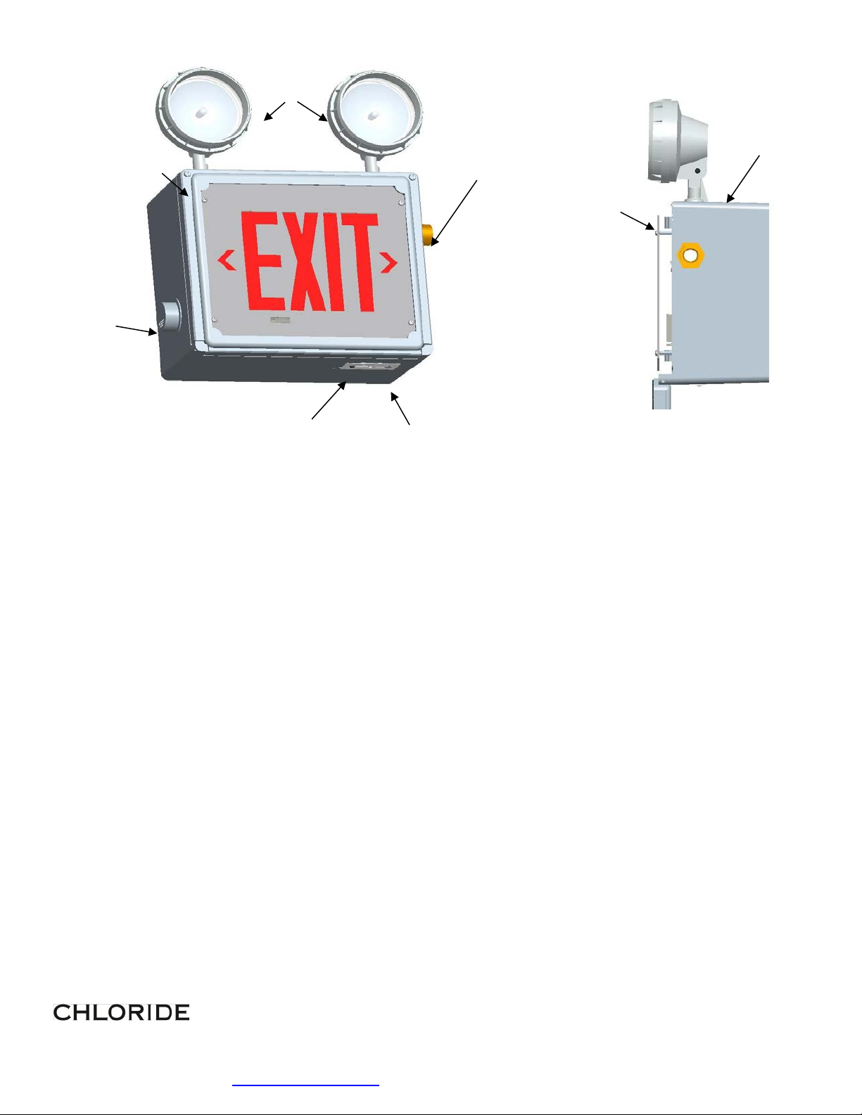
HZ SERIES
EMERGENCY TWO-HEAD LED EXIT
IMPORTANT
SAFEGUARDS
When using electrical equipment, basic safety
precautions should always be followed, including the
following:
READ AND FOLLOW ALL
SAFETY INSTRUCTIONS
All servicing should be performed by qualified personnel
only.
Do not mount near any heat producing equipment.
Equipment should be mounted in locations and at heights
where it will not be readily subjected to tampering by
unauthorized personnel.
The use of accessory equipment not recommended by the
manufacturer may cause an unsafe condition.
Do not use this equipment for other than intended use.
In Class I Division 2 locations, do not replace any
non-metallic hardware with metal hardware. Contact
authorized agent for factory replacement parts.
In Class I Division 2 areas, install equipment in
accordance with appropriate NEC articles plus any
other applicable codes.
To avoid static discharge, do not attach any ungrounded
metal hardware to the enclosure.
Do not store or place flammable materials near lamp.
Install only grounded wiring systems to supply this
equipment
CAUTION – ensure lamp heads are positioned
so they are aimed below horizontal
CLASS I DIV 2
HAZARDOUS LOCATION
GROUPS A, B, C, AND D
ZONE 2 GROUPS IIC, IIB AND IIA
CLASS II DIV 2 GROUPS F AND G
AND CLASS III DIV 1 AND 2
INSTALLATION AND OPERATING
INSTRUCTIONS
Do not use this equipment outdoors.
CAUTION: Halogen cycle lamp(s) are used in this
equipment. To avoid shattering: Do not operate
lamp in excess of rated voltage, protect lamp
against abrasion and scratches and against liquids
when lamp is operating, dispose of lamp with care.
Halogen cycle lamps operate at high temperatures.
Do not store or place flammable materials near lamp.
CAUTION: “To avoid electrical overload, total
connected lamp load (factory and field installed)
should not exceed output rating”.
Free installation area of hazardous atmospheres
before wiring equipment or servicing, this reduces
the risk of accidental explosion due to inadvertent
battery shorting during installation.
SAVE THESE
INSTRUCTIONS
WARNING – Shut off AC power to branch
circuits to which units will be connected. All
wiring should be per NEC wiring methods for
Hazardous locations.
To maintain warranty, equipment with
batteries must be installed or placed on charge
within prescribed period after shipment.