Chongqing Xiegu Technology X5105 User manual
HF/50MHz Portable
HF Transceive
r
X5105
Instruction Manual
Chongqing Xiegu Technology Co.,Ltd.
V1.0.04-02

Catalogue
1
Introduction………………………………………………………2
Panel Control & Switches.………………………………...3
Left-side Jack….....................................................6
Right-Side Jack……………………………………….…………7
Hand Microphone Functions…………………….………8
External Interface…………………………………….……….9
Internal Battery Charging & Maintenance……..10
External Power Supply Interface……………….….12
Menu Operation…………………………………….……….14
User menu…………………………………………..…….15
LCD……………………………..……………………...…….16
On/Off Transceiver………………..…….……….……17
Battery level / voltage……………………...……….18
Operating Band Selection……………….…………19
Operating Mode Selection…………….……..…..20
Adjusting the Audio Volume Level………..……21
Adjusting Power output (Po)……………….….…22
Built-in PTT button………………………………..…..23
Setting operating frequency………………..…….24
Automatic antenna tuner (ATU)……………..….25
Receiver Incremental Tuning(RIT) ………….….26
Automatic gain control(AGC)……………….….27
Pre-amplification/Front end Attenuator....28
Noise Blanker(NB)………………………………..…29
Data Modem (MDN)……………………..………..30
SPL & VFO Setting…………………………….…….31
VFO/MEMO mode Switching…………………..32
Locking Front Panel Controls/Turning The
Poor Light On /Off……………………………….….33
CW transmission………………………………..…..34
CW AUTO transmission……………………………36
Standing Wave Ratio Scanner(SWR)…………37
Digital Audio Filter (AFF)…………………...……38
Built-in or External MIC / line Input
Selection……………………………………………….…39
Speaker/Headset Mode Switching(SPK)……40
Memory Storage( MW)………………….……….41
Channel Tag (TAG) ………………………………….42
Card Sign Number(CSN)……………….…………43
Data communication with computer……...44
Deploying System Parameter……………….……45
Reset…………………………………….………….………..47
Parameter Configuration Chart…………….……….48
Computer control Command…………….………..….49
Band Voltage Data Chart…………………….………….49
Specifications………………………..……..…………………50
Packing List……………………..………………..……….…..51
XieGu Radio Products Connections With XPA125
Amplifier Chart………………………………………….….52
CE-19 expansion card interfacing……………...….53

Panel button
2
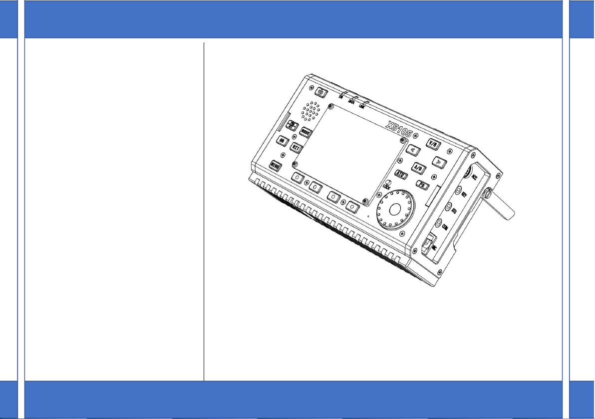
X5105 is a short-wave all-mode transceiver that is pretty interfaceable, which integrates all the functions required for
shortwave amateur radio operation in a very limited volume, and realizes a interfaceable / mobile shortwave device in a real
sense. Its powerful functions and performances make it easy for you to respond to various situations and receive signals
from around the world.
HF+50MHz all mode 5W output
Extremely small size, about 168*93*47mm,interfaceable
3.6-inch large screen lattice LCD
Built-in large-capacity lithium battery pack(3800mAh @ 12V)
Built-in automatic antenna tuner
Built-in digital baseband, can achieve many advanced functions:
Digital noise reduction NR
Digital NOTCH
Digital filter
Direct decoding of amateur radio data mode
With external adapters, data communication can be done directly without the need for a PC or a separate modem
CW automatic calling unit
Built-in high stability TCXO
Manual button / automatic button mode switch
Wide working voltage range
For a better experience of this machine , read this manual carefully before use so as to fully understand the operation
method of the X5105 .

Panel button
3
11
22
23
X5105
T/R DATA LINK
LOCK
PRE
ATT
MODE
MENU
V/M
A/B
NB RIT
ATU Po
<
1
2
3
4
5
6
7
8 9 10
12
13
14
15
16
17
18
192021
A
B
C

Panel button
4
1
Power switch
Press this button for one second to turn
on or off the radio.
2
MODE button
short press this button changes the
current mode of work and cycles in the
following order:
[ LSB-USB-CW-CWR-NFM-AM ]
3 PRE/ATT button
Short press this button will turn on or off
the preamplifier or attenuator in the
following state:
[ PRE=ON---ATT=ON---PRE/ATT=OFF
]
4 RIT button
Short press this button to turn on receive
frequency trim function.
5 NB button
Short press this button will turn NB
function on or off.
6 MENU button
Short press this button will switch the
multifunction menu currently displayed.
7
~
10 Multifunction menu button
Short press these four buttons to turn on
or off the corresponding functionality
displayed in the menu area on the current
screen.
11 LOCK button
Short press this button will lock all
button, knob action on the panel;
Long press this button for 1s, sets the
screen backlight to turn off / on.
12 Main knob
The main tuning knob of the station, it
can be used not only for frequency
regulation, but also for setting
parameters.
13 ATU button
Short press this button, the automatic
antenna tuner will be connected to the
antenna interface;Long press this
button to tune the automatic antenna
tuner .
14 Po button
Short press this button, and with the
main tuning knob, you can adjust the
transmission power. The adjustment
range is from 0.5 W to 0.5 W, and the
stepping is to 0.5 W.
15 A/B button
Short press this button, switching
between VFOA / VFOB.
16 < button
Short press this button, the current
frequency step moves one bit to the left.
17 > button
Short press this button, the current
frequency step moves one bit to the left.
18 V/M button
Short press this button will switch
between VFO mode and MEMO mode.
19 UP button

Panel button
5
Short press this button, will switch to
higher frequency band.
20 DN button
Short press this button, will switch to
lower frequency band.
21 Volume- button
Short press this button to reduce the
current volume.
22 Volume+ button
Short press this button to increase the
current volume .
23 PTT button
Press this button and the station will
go into launch mode.
A T/R pilot lamp
In receiving state,It shows green
In setting state,It shows red
B DATA pilot lamp
The pilot lamp will flicker when data
communication occurs.
C Link pilot lamp
When the host is connected to the
peripheral, the indicator lights up.
Left interface
6
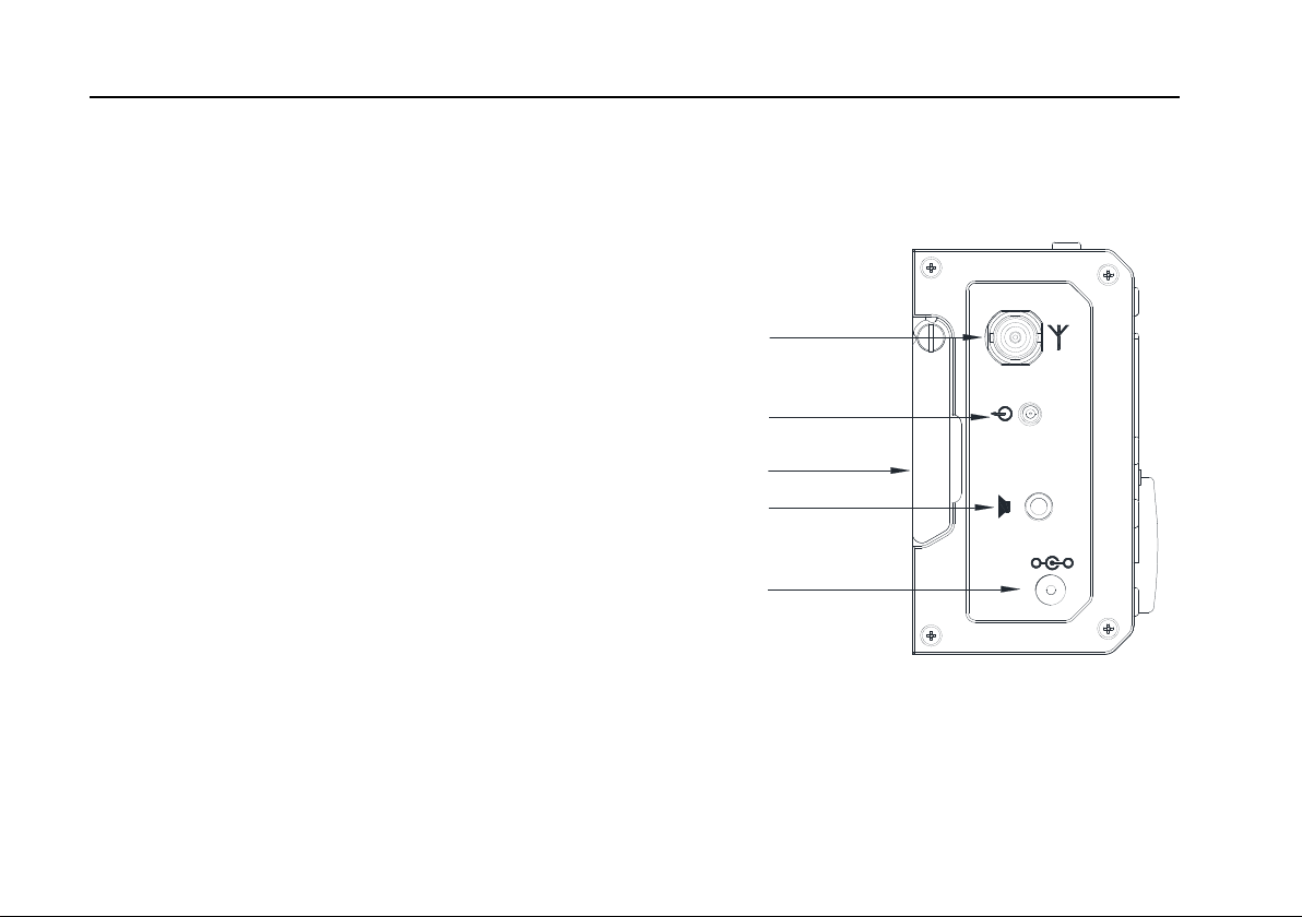
24 Antenna interface
BNC interface, impedance 50Ω.
25 Intermediate frequency signal outlet
The output receives the first intermediate frequency
signal.
26 Left supinterface
Break out the bracket when use it. After using, retract the side
guard.
27 Earphone interface
This interface is a 3.5mm stereo socket (3 wires) for connecting
earphone devices.
*this interface function of different versions of the X5105 is
different, be careful to distinguish.
28 DC power interface
External DC power input interface, using the distribution of power
wires to the external DC power supply to this interface. External
DC power must be able to provide 13.8 V @ 3A power output. The
interface is also used to charge the battery inside the machine.
+
-
EXT DC
24
25
26
27
28
Right interface
7
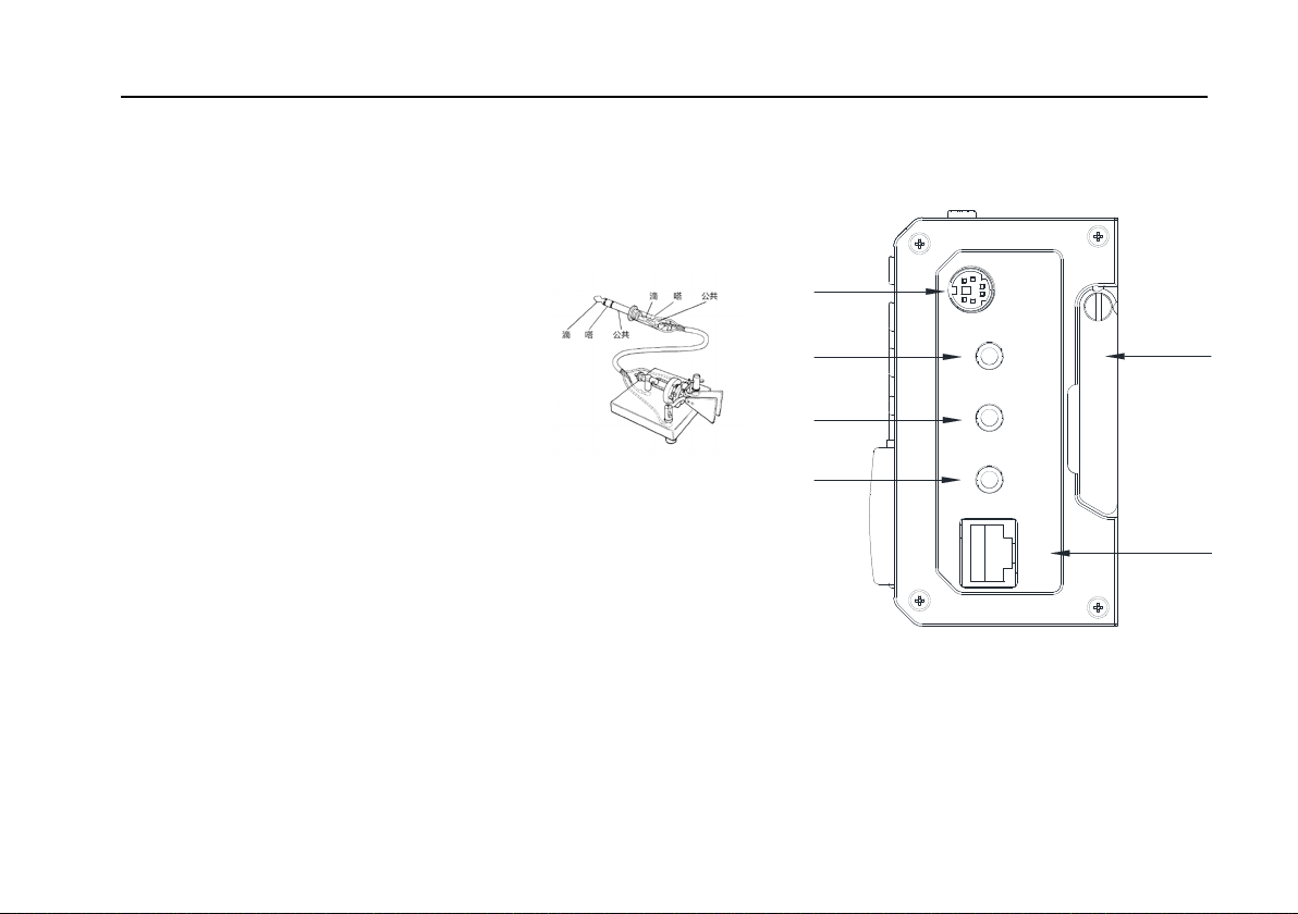
29 ACC interface
The interface is an 8PIN miniature DIN interface, which can be used for external power amplifier connection control, PTT control, band signal
transmission, and it can also be used to do data communication when the audio signal input / output.
30 button interface
The interface is a 3.5mm stereo interface for connecting manual / automatic Telegraph buttons.
The button connection is shown
in the figure:
For manual button,
"di" and "da" need to
be connected together.
31 ATU interface
The interface is a 3.5mm interface (3-wire) for external day-tuning control.
*This interface function is not yet available.
32 COM interface
The interface is a 3.5mm interface (3-wire) for computer-aided control
system connections and firmware updates.
33 Right supinterface
Break out the bracket when used. After using, retract the side guard.
34 MIC(microphone ) interface
Connect the configured multifunctional hand-held microphone to this interface.
ACC
KEY
ATU
COM
MIC
29
30
31
33
32
34
Hand-held microphone function
8
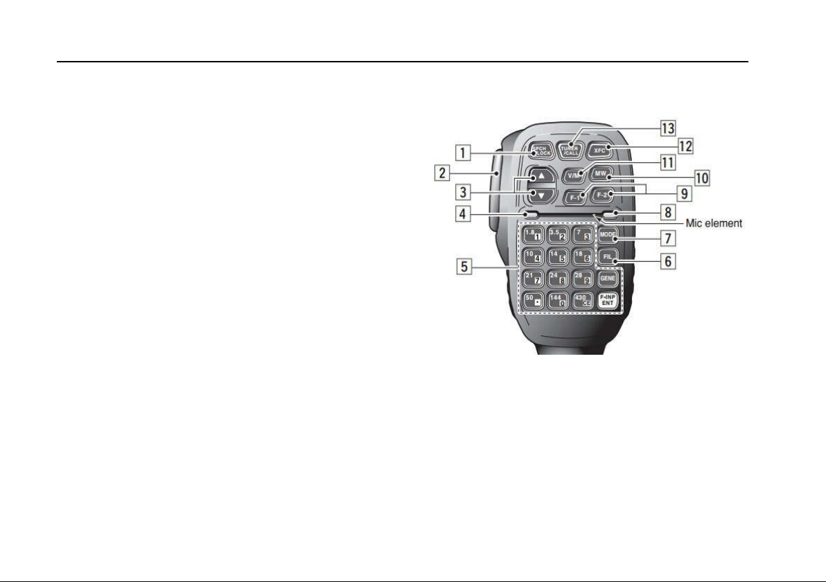
1、LOCK button
Lock button
2、PTT button
Launch control button
3、Up / Down
Frequency increase, minus button
4、Transceiver pilot lamp
Hand operation pilot lamp
5、Digital button region
Digital buttonboard area
6、FIL button
Filter selection
7、MODE button
Host mode selection
8、Functional pilot lamp
Temporary no indication
9、Function button
F1/F2 custom setting button
10、MW button
Store operation
11、V/M button
Frequency / channel switching
12、XFC button
Temporary no function
13、TUNER button
Long press to start automatic sky
modulation tuning in Machine

External interface description
9
1、 Microphone interface
2、 CIV interface
3、 Earphone interface
4、ACC interface
5、button connection
Note:滴(di)嗒(da)公共(public)
MIC
MDATA
GND
MIC
MICE PTT
MSVSW
NC
+8V
TXD
RXD GND
信号
信号 GND
PTTBAND
AF_IN
AF_OUT
ALC
DATA
+8V
GND

Charge and maintenance of battery in machine
10
X5105 has built-in 3800mAh polymer lithium battery pack. When the external power supply is not connected , a power supply is supplied to the whole
machine by a battery pack ;When the external power supply is connected , the internal circuit of the machine is automatically switched to the external power supply .
Screen display information in shutdown
charging
Vext: Display external supply voltage
Vbat: Displays the current real - time voltage of
the battery
5、The maximum charge time is about 10~12 hours. When the battery is fully charged, the
charge will automatically stop, and the screen will show the end of the charge, as shown in
the right picture.
After charging, the battery voltage is generally between 12. 1 V and 12. 5 V, which are all
normal.
Charging method:
1、 In the MENU - 7,【CHG】option is the charging switch.
2、 Select "Charger ON" and open the charging function.
3、 Select "Charger off "and turn off charging.
4、 Set the external power supply voltage between 13.5V and
15.0V, connect to the X5105 external power supply
interface, the host will start charging automatically.
Note: on shutdown, the X 5105 will automatically be
charged by inserting the appropriate external power
Charging…
Vext=13800mV
Vbat=11800mV
Charge Finish
Vext=13800mV
Vbat=12200mV
Display information on screen after charging
Charge and maintenance of battery in machine
11
○ In battery-powered mode, when the battery power is running out, the charge indicator in the upper-right corner of the screen is displayed as
,indicating that power should be charged or switched to an external power source immediately. During the charging process, the shell has
a slight heating phenomenon.
○ In normal use, the battery life is limited. When there is a significant drop in capacity or a charge failure, contact the dealer to replace it(The battery
quality guarantee period is 3 months, It needs to be paid for replacement exceed the quality guarantee period ) .
When using external power supply, do not exceed the rated voltage range of the equipment,
otherwise it will cause damage to the equipment.
When abnormal heating occurs at the bottom of the housing near the battery, shut down immediately and
place the equipment in a safe and ventilated place. Please contact us as soon as the safety condition is
confirmed.
Connection of external power supply
12
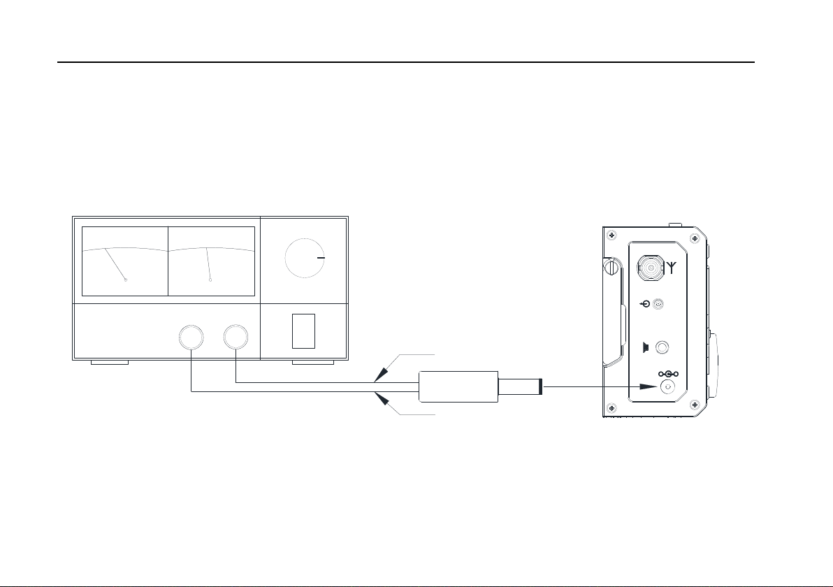
The X5105 can use a 13.8V external DC power supply. The current load capacity of DC power supply is at least 3A. The randomly attached power
cord can be used to connect the station to the DC power supply.
When connecting DC power, please carefully follow the logo below to avoid the power polarity reverse connection.
The white wire is connected with the positive pole of the power supply , and the metal shield wire is connected
with the negative electrode of the power supply .
Note:金属屏蔽线(Metal shielded wire);白色线(White line)
+
-
EXT DC
POWER SUPPLY
VOLT ADJ
+-
白色线
金属屏蔽线
ON
OFF
X5105
Connection of external power supply
13
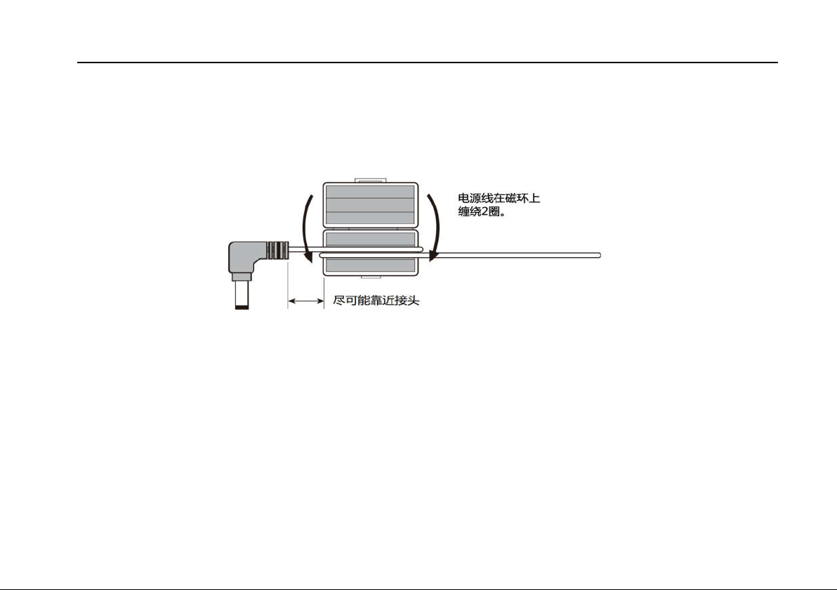
In order to prevent the external interference from entering the radio station through the power supply and the radio frequency interference radiating
through the power wire, the EMC magnetic ring can be installed on the power supply wire when the X5105 uses the external power supply. The magnetic
ring shall be installed as close as possible to the side of the power plug.
Note:电源线在磁环上绕两圈(Wrap around two turns.);尽可能靠近接头(As close as possible.)
In the use of external power supply, please carefully check the polarity of power wires to avoid polarity back
wiring.
The limited warranty of this radio does not include damage caused by external power connection error or
abnormal supply voltage.
Operation
14
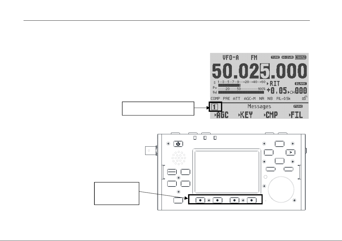
A multi - function menu mode is used in X5105 to perform various functions for use or shutdown . All functions are distributed in 9 menu pages,
with four options per page.
The menu is switched as follows:
Short press MENU button, the menu page number in the lower left corner
of the screen starts flashing;
Rotate the large button to the desired menu page.
The four multifunctional buttons below the
screen correspond to the displayed function menu.
Menu page number
X5105
T/R DATA LINK
LOCK
PRE
ATT MODE
MENU
V/M
A/B
NB RIT
ATU Po
<
Multifunction
button

User menu
15
Menu page Function
1
Copy the current VFO to the
background Different frequency transceiver Digital noise reduction Digital NOTCH
2
AGC Filter selection Scanning receiving mode Standing wave scanner
3
Write channel information to
VFO Store current settings Clear current channel Custom channel name
Long press to enter
editor
4
CW insert state button manual / automatic mode
switching
Automatic buttoning rate
adjustment /
5
Preset CW message 1 Preset CW message 2 Preset CW message 3 When starting up display
call sign editor
Long press to enter message
editing Long press to enter message editing Long press to enter message
editing
Long press to enter the
editor
6
noise elimination voice compression Multifunction menu switching Power / voltage display
switch
7
charges switch Internal, external MIC/ external audio
input IF output Firmware version display
8
Digital MODEM Carrier tracking(MDN=ON) Frequency tracking(MDN=ON)
/
9
Digital audio filter High-pass filter Low pass filter Speaker / headset mode
selection

Operation
16
The X5105 uses a 3.6 inch black and white lattice LCD screen to display all the status information on the machine for easy observation. The visibility
in the outdoor sun is also pretty good.

Operation
17
Dear users, hello. In order to make you become familiar with the functions of X5105 interfaceable transceiver as soon as possible and be proficient in
the operation, please read the instructions of this manual carefully and understand the powerful function of X5105. Here we go!
Turn on / off the transceiver
1、Turn on the transceiver: Press button for one second.
2、Turn off transceiver: When the machine is on,
Press button for one second.
Hard reset: when the host system is in a dead state, such as button not responding, or unable to exit the launch state and button not responding,
Long press switch button and hold for more than 8 seconds, reset MCU and force shutdown.
X5105
T/R DATA LINK
LOCK
PRE
ATT
MODE
MENU
V/M
A/B
NB RIT
ATU Po
<
开关键

Operation
18
Battery power / voltage display
If the X5105 transceiver is not used for more than 30 days, we recommend that you connect the external power to charge the device until the display
is complete. See the operating instructions in the [ charging ]section for the specific operation steps.
1、 The upper-right corner of the LCD screen will show the
current percentage of the battery remaining when using
a built-in battery to power the transceiver.
2、 When using an external power supply, switch to page 6 of
the menu and press [VLT] button, which displays the

Operation
19
Operating Frequency Selection
Operation method:
Press DN or UP button to switch to the next or previous operation band, respectively.
The opening of the 5 MHz band depends on the laws and regulations of the country (or region) in which it is located.
The frequency of different versions of the machine varies according to the laws and regulations of the country in which it is located.
VFO-A and VFO-B are two independent VFO modes, which can be set to different working states respectively, see [VFO settings].
3.5MHz 7.0MHz 10MHz 14MHz
18MHz
21MHz
24MHz
1.8MHz
28MHz
5.2MHz
50MHz
The frequency range of X5105 covers
0.5~54MHz
.
The amateur frequency in this
range is divided into multiple bands, which can
PTT DN UP
HF+50MHz TRANSCEIVER
频段向下 频段向上
Table of contents
Other Chongqing Xiegu Technology Transceiver manuals


Popular Transceiver manuals by other brands

Garmin
Garmin GTR 200B installation manual

Yaesu
Yaesu FT DX 3000 operating manual

Iridium
Iridium NAL Research Corporation 9602-NAL user guide

ABITRON
ABITRON CS TRT-1-1 Series Technical documentation

Ten-Tec
Ten-Tec ARGONAUT VI 539 user guide

Technisonic Industries Limited
Technisonic Industries Limited TFM-556 Installation and operating instructions


