Chongqing Xiegu Technology X6100 User manual
1
X6100, an ultra-portable short-wave transceiver that adopts high-performing
radio platform architecture, powerful baseband and RF units, receiving structure and
24bit sampling and large dynamic RF front-end unit, can obtain extremely high radio
receiving indicators.
The whole device integrates rich and varied operation functions and desktop-like
functions, such as recording call, variable bandwidth digital filter, digital noise
reduction and so on, which brings you a new cognition and experience on amateur
radio. With its compact structure and appearance, you can immediately set forth on a
journey with it, get close to nature, and enjoy the fun of outdoor communication.
● HF/50MHZ full mode (supporting data communication)
● 4-cun high-resolution color screen (800*480)
● Built-in large capacity lithium battery pack (3000mAh, 12V)
● Built-in efficient automatic antenna tuner
● Integrated standing wave scanner and voice pager
● Integrated modem, preset message, CW automatic call
● which can realize wireless audio, keyboard and mouse operation
● Integrated USB line control/transmission, supporting USBHOST.
● Standard high-stability TCX0 internal clock source
We strongly recommend you to read through this Manual to rapidly keep abreast of the
operation & control method of the X6100 before using it.
Safety Precautions
That changes or modifications not expressly approved by the party responsible for
compliance could void the user's authority to operate the equipment.WARNING:
This device complies with part 15 of the FCC Rules. Operation is subject to the following two conditions: (1)
This device may not cause harmful interference, and (2) this device must accept any interference received,
including interference that may cause undesired operation.
For a Class B digital device or peripheral, the instructions furnished the user shall include the following or similar
statement, placed in a prominent location in the text of the manual:

advance.
Note:
This equipment has been tested and found to comply with the limits for a Class B digital
device, pursuant to part 15 of the FCC Rules. These limits are designed to provide reasonable
protection against harmful interference in a residential installation. This equipment generates,
uses and can radiate radio frequency energy and, if not installed and used in accordance with
the instructions, may cause harmful interference to radio communications. However, there is
no guarantee that interference will not occur in a particular installation. If this equipment does
cause harmful interference to radio or television reception, which can be determined by
turning the equipment off and on, the user is encouraged to try to correct the interference by
one or more of the following measures:
- Reorient or relocate the receiving antenna.
- Increase the separation between the equipment and receiver.
- Consult the dealer or an experienced radio/TV technician for help.
Do not use this device in lightning weather. Disconnect the power supply and antenna
in
Do not touch the antenna during the transmission of the device.
Do not apply AC power to the DC interface on the side panel of transceiver. Otherwise it may
cause fire or damages to the device.
Do not apply more than 15VDC voltage to the DC interface on the side panel of
transceiver. Otherwise it may cause fire or damages to the device.
Do not reverse the polarity of the power cable. Otherwise it may cause fire or damages to the
device.
Do not operate or touch the device with wet hands. Otherwise it may cause electric shock or
damages to the device.
In case of smoke or peculiar smell, cut off the power supply immediately, remove the
In case of smoke or peculiar smell, cut off the power supply immediately, remove the power
cable, and then contact the supplier.
power cable and then contact the supplier.
Connect the equipment into an outlet on a circuit different from that to which the receiver is
connected.
1
2

3
Do not use the device in areas, vehicles or aircraft where it is prohibited.
Do not use this device while driving or operating engineering equipment.
Do not use the device in petrol stations, gas stations or the place with combustible gas
around.
Do not use the device in hospitals or in an environment where people wear medical
devices.
Do not expose the device to rain, snow or any liquid. Otherwise it may cause damages to
the device.
Do not use headphones at high volume.
Do not disassemble or modify the device.
Do not place the device near the heat source or in direct sunlight.
Do not place the device in a dusty or damp place.
Do not place the device in a poorly ventilated place and do not block any radiator on the
device. Otherwise, the deceive may be damaged due to overheating.
Do not wipe the device with organic solvents, such as benzene or alcohol. This may
damage the surface of the equipment.
Do not apply impact force on the device. Otherwise it may cause fire or damages to the
device.
Do not place the device in the area with temperature range beyond -10°C~+55°C.
Do not place the device in the area with temperature range beyond -10°C~+55°C.

4
Battery Precautions
This device contains lithium-ion battery components, so improper use may result in
dangers such as smoke, fire or battery rupture.
■ The battery pack is installed inside the backplane of the equipment. Do not hit
the backplane of the device.
■ Do not place the device in a place where the temperature is higher than 60°C;
otherwise, the battery pack may rupture or catch fire.
■ Do not place the back of the device near heat sources, such as stove fire or direct
sunlight.
■ Do not weld, disassemble or modify battery components by your won. This can
lead to protection failure and battery damage, which can further lead to fire and other
hazards.
■ In case of obvious deformation, seepage or peculiar smell at the installation place
of the battery pack, the device shall not be further used, and distributor shall be
contacted immediately for assistance.
■ Do not use the device beyond its temperature range; otherwise, the service life of
the device and battery pack may be reduced or damaged.
■ Do not leave the battery pack in fully charged or fully discharged state for a long
time. Otherwise, the service life of battery pack will be shortened. Please maintain the
electric quantity of battery pack within 40%~50% if the device is to be left unused for a
long time, and then keep it properly.
■ The service life of the built-in battery pack is about 3~4 years generally. Please
replace the battery pack once its service life reaches this period. Even if the battery
still works, its performance will be significantly reduced and service time will be
greatly shortened. The battery pack can be generally charged and discharged for
300~500 times. This depends on specific usage conditions.
■ Do not charge the device with other non-compliant chargers.
■ Pay attention to the condition of the device when charging. Stop charging
immediately in case of any abnormality.
■ Do not charge the device in vehicles under direct sunlight.
Important Note
■ Make sure you have had relevant operating certificates or permissions before
making a call on the frequency band of amateur radio.
5
■ Make sure the antenna feed system meets the transmitting requirements before
actual transmitting.
■ The device may be hot after continuous and long-term transmitting (such as FT8
operation). Please appropriately extend transmitting interval and strengthen external
heat dissipation.
■ Please place the device in a safe and reliable place and keep it away from children
or unauthorized persons.
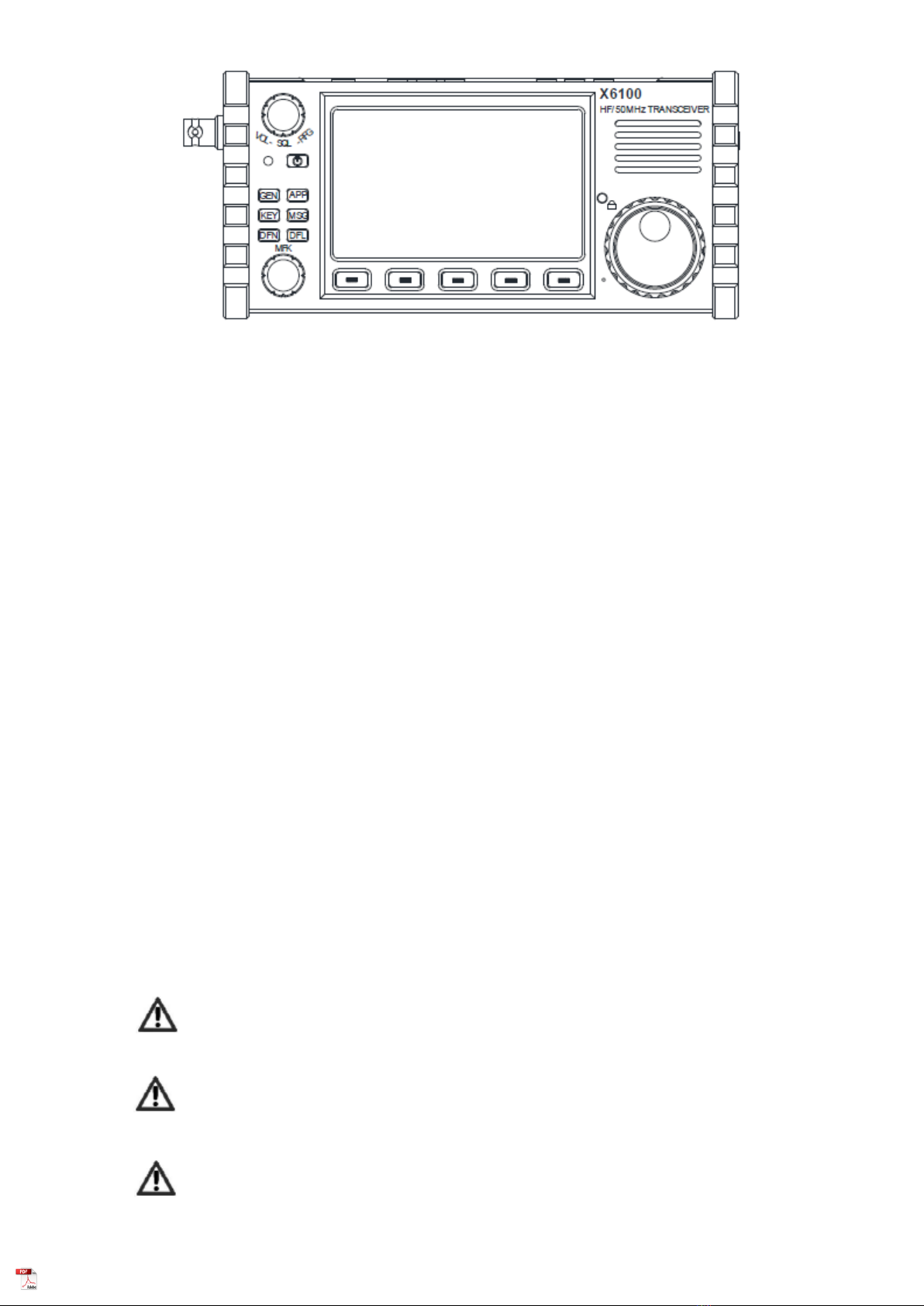
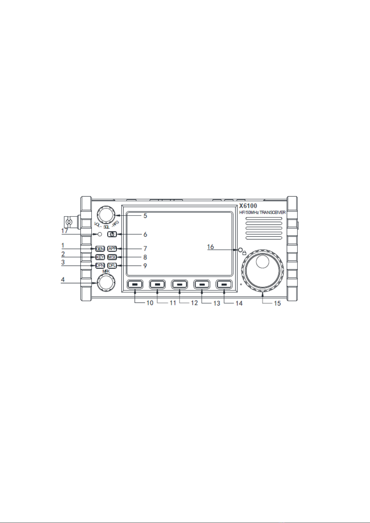
I. Panel Instructions
Front panel
1 GEN button
9 DFL button
Press it to bring up the general settings
menu.
Press it to bring up digital filter settings
interface
2 KEY button
10~14 Multi-function button
Press it to bring up tapper settings
menu.
Press it to execute functions displayed on
screen.
3 DFN button
15 Main knob
Press it to bring up the menu of digital
functions.
Rotate it to adjust frequency.
4 MFK multi-function knob
16 Lock button

6
Default:
Customize:
5 VOL/SQL/RFG knob
Default: volume control.
Press the knob to adjust SQL muting
depth.
Press the knob again to adjust RFG
gain.
6 Power button
Press and hold it to turn on the power
supply of transceiver.
Press and hold it for 1s to turn off the
power supply of transceiver.
7 APP button
Press it to bring up function menu.
8 MSG button
Press it to bring up information editing
and storage interface.
Long press for 1s to lock the keys operation on
panel.
Long press for 1s again to unlock.
17 Power supply/TR indication
The indicator light is green after startup.
Left plate
18 ANT
BNC interface, 50Ω, for antenna
connection.
19 I/Q OUT
IQ signal output port 3.5mm stereo
socket.
20 DC IN
External power input port, 5525 type.
Note: input voltage shall not be higher
than 15V DC.
Right plate
21 CARD
microSD memory card slot
22 DEV
USB port. Slave interface

7
23 HOST
USB port. Host interface.
24 S/P
External speaker/headphone interface,
with speaker or headphone output can
be set via menu. It is a 3.5mm stereo
interface achieving stereo output.
Note: short circuit or silence will be
caused if plugging the single track plug
externally.
25 KEY
It is a 3.5mm stereo interface used to
connect manual/auto tapper. See page 8
for connection.
26 ACC
It is a 3.5mm stereo interface. See page
8 for interface definitions.
27 MIC
Hand microphone interface. The
interface is of type RJ45.
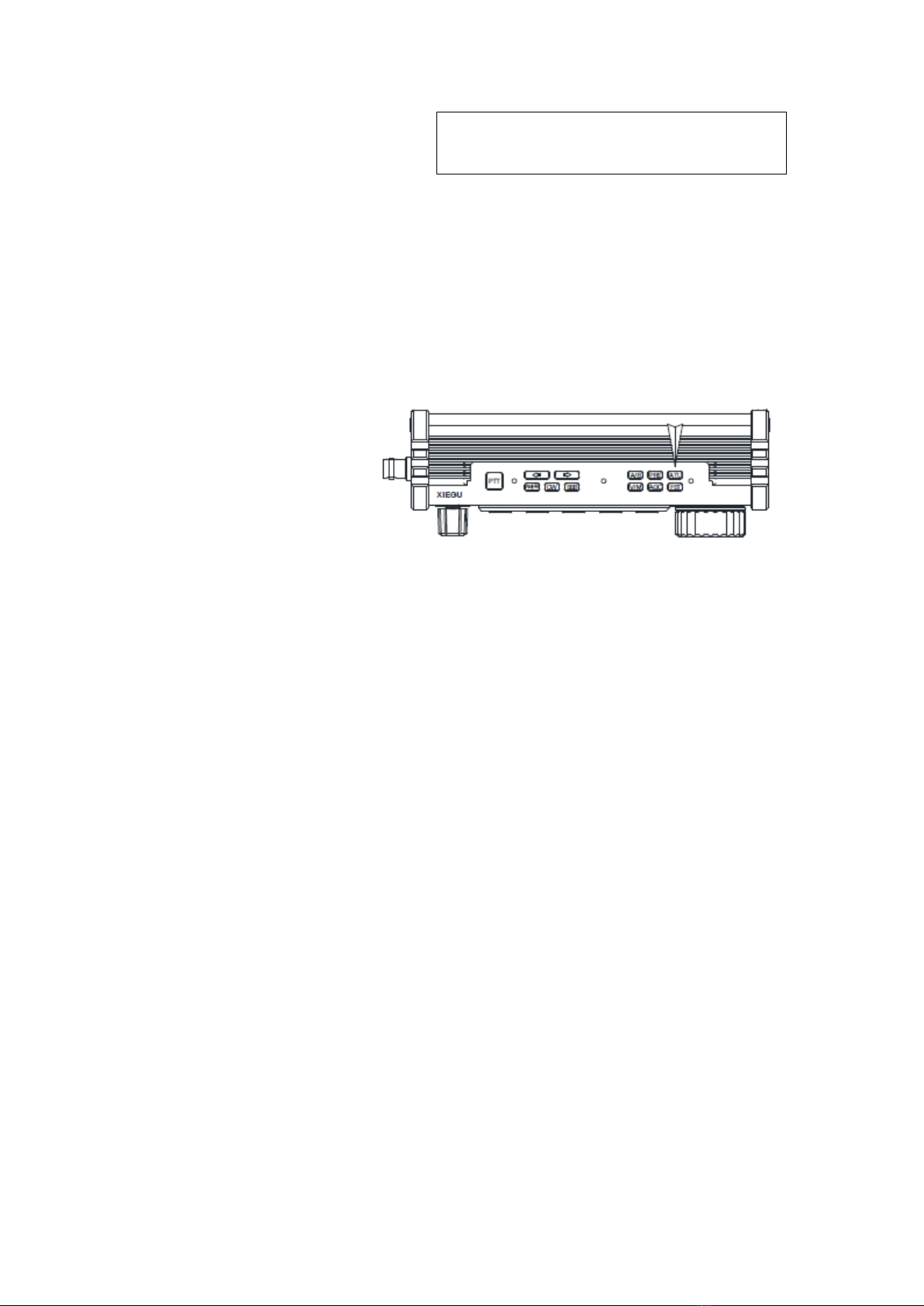
Top button
28 PTT
PTT button on device body.
29 AM|FM
AM/FM mode switch button.
30 CW
CW mode switch button
31 SSB
34 FST
Fast step selection button
35 ATU
Built-in antenna tuner access/tuning button
36 PRE
Pre-amplifier/pre-attenuator switch
37 A/B
8
SSB mode switch button
32 V/M
VF0/MEM0 status switch
33 AGC
AGC switch/speed selection button
VF0A-VF0B switch button
38~39 Left and right switch
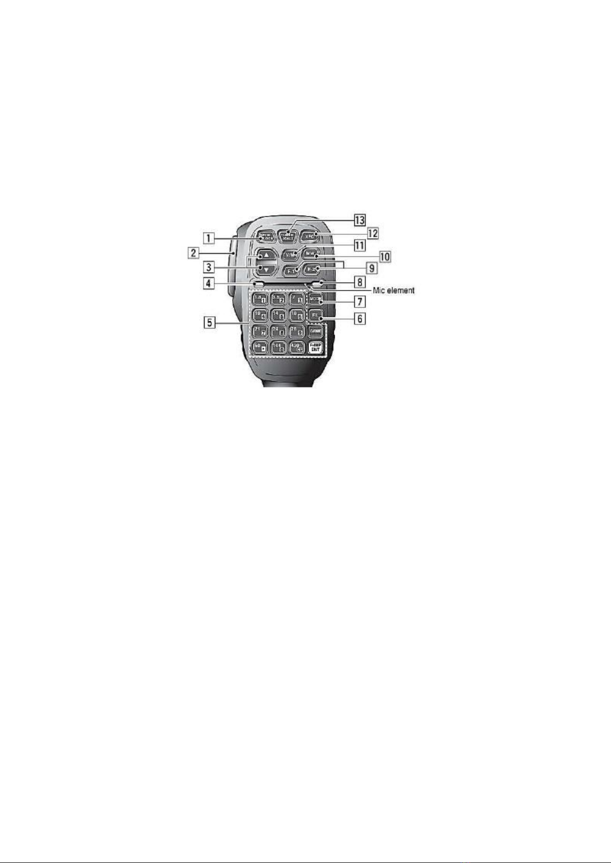
Hand microphone button
1. LOCK button
2. PTT button
3. Up/down
detailed in system menu 1)
4. Transceiver indicator light
5. Figure button area
6. FIL button
7. MODE button
8. Functional indicator light
9. Function button
2&3)
10. MW button
11. V/M button
12. XFC button
13. TUNER button
Lock button
Transmitting control button
Hand microphone operation indicator light
Figure keyboard area
Filter selection
Selection of working mode of host
No
F1/F2 key (user-defined, detailed in system menu
Memory operation
No function temporarily
Long press to start antenna automatic tuning
Interface Definition
Microphone port Definition of ACC interface

9
Connection of S/P Port Definition of I/Q OUT interface
Connection of KEY Port
Connect manual/automatic tapper
according to the schematic diagram
shown in the right figure.
Note :
● If the connector of the manual
tapper is a 6.5mm 2-core plug, please
change it to a 3-core 3.5mm stereo plug
according to the wiring method shown
in the right figure, and connect the
trigger end of the electric key to the
"Di" or "Da" terminal.
●Take care that direct use of the
2-core to 3-core adapter or incorrect
wiring may result the radio in CW
transmission status all the time.
●Using plugs of other specifications may damage the socket.
● X6100 may switch to transmitting mode if plugging in or unplugging the tapper
plug when it is working.
● Please cut off the power supply of X6100 before connecting or disconnecting the
tapper.
Power source wiring
13.8V external DC power supply can be used for X6100. The current load capacity of
DC power supply shall be at least 3.5A. Attached power lines can be used to connect
to radio and DC power supply.
DC power supply shall be connected in strict accordance with following figure to avoid
reverse polarity connection.
Di
Di
Da
Da
Com
mon
Com
mon

10
■ EMC magnet ring can be applied on power lines to prevent external disturbance
from entering radio via power lines and radio-frequency interference in radio from
radiating externally via power lines when external power supply is adopted for X6100.
Magnet ring shall be installed at the side closing to radio to greatest extent.
Charging
The X6100 radio shall be charged by the attached charging adapter. The radio can be
charged by connecting the AC end of charging adapter with electric supply and
inserting the output end into the DC interface at the left of X6100.
The host will automatically stop charging once the charge is completed.
Note :
■ Polarity of power lines shall be carefully inspected to avoid reverse polarity
connection when external power supply is adopted.
■ Reverse connection of power may cause severe damage to the radio.
■ Do not charge the radio with any other charger that does not meet the
specifications. Otherwise, the device may be damaged
Caution!
1. The charging adapter can only charge the X6100 and cannot be used for transmitting
as there is a risk of damaging the device.
2. Under no circumstances shall the DC port on the left of the X6100 be connected to a
voltage higher than 15VDC. Otherwise, serious device damage may occur.
II. Screen Display Interface

11
①Status display area 1
This area displays SPL, ATU, SQL,
NB, NR and ANF switch status.
②Volume tag
Display volume/noise level/RF gain
adjustment. Short press the volume
knob to switch the above three status.
③Multi-function tag
The figure shows the transmitting
power adjustment tag. Items of the tag
displayed can be rapidly set via menu.
④Spectrum display area
It displays the signal strength of about
-122dBm at minimum
⑤Waterfall plot display area
⑥Multi-function menu area
Short press the corresponding button at
the bottom of the screen to operate
corresponding functions.
⑦Main VFO frequency display area
⑧Status display area 2
This area displays the status including
lock/USB port/battery/volume.
⑨VFOB display area
⑩Status display area 3
This area displays PRE/ATT/mode /AGC
status
○
11 Table header area
This area displays S table and CW frequency
aligned windows
○
12 Signal strength dBm display
Basic Operation
Turn on/off radio

12
1. Press the on-off button for 1s to
turn on the radio.
2. Press the on-off button for 1s
again to turn off the radio.
Adjust audio volume
1. Turn the volume knob to the
left or right to adjust the output
volume.
2. Short press the volume knob to
switch volume/muting depth/RF gain
adjustment.
Operating frequency band and mode selection
Follow the instructions below to
select the amateur band and set
mode.
● Frequencies beyond the
amateur band can only be received
while cannot be transmitted.
Adjustment of RF gain and muting level
Proper RF gain can facilitate to improve the quality of signal received. In general,
appropriately reducing the RF gain value at some low-frequency ranges with strong
interference can significantly improve the hearing.
Adjustment methods of RF gain:
1. Short press the volume knob to bring up the RF GAIN setting items. The tag on the
left side of the screen will display RF GAIN.
2. Rotate the volume knob to adjust the RF gain value.
SQL setting
When muting is necessary for signals or noise less than a certain amplitudes,
appropriate muting level can be set to disable the audio switch without signal so that the
speaker can be muted.
Operation methods:
1. Short press the volume knob to bring up the RFGAIN setting items. The tag on the
left side of the screen will display SQLLevel.
2、 Rotate the volume knob to set the muting level. At the same time, the muting grade
will display on the screen.

13
■ The muting grade gradually strengthens from S1 ~S9, corresponding to strength.
For example, when the muting grade is set to be S3, it indicates that the speaker will
sound when the signal strength is more than S3. Otherwise, the speaker will in the silent
mode.
Pre-amplifier/pre-attenuator
The pre-amplifier can improve
the receiving effect of some
weak signals of high frequency
range and the sensitivity of the
receiver.
Pre-attenuator can improve
barrage jamming caused by
strong signals and the
performance of receiver.
1. Short press the [PRE] button at the top of the radio, and the character PRE appears at
the top of the screen, indicating that the pre-amplifier has been turned on.
2. Short press [PRE] button again and the character ATT will appear on the top of the
screen, indicating that the pre-attenuator has been turned on.
3. Short press [PRE] button again and no character will appear on the top of the screen,
indicating that the current state is shoot-through state.
■ Before they are used in frequency range less than 14MHz, disabling the
pre-amplifier is recommended so that the radio can be in the shoot-through state, which
is conducive to strengthen the front-end performance of the receiver and reduce the
influence of interference signals.
■ When the level displays that the received signals exceed _40dBm, turning on the
pre-attenuator is recommended to avoid the decreasing of the dynamics of the receiver
due to strong signals.
Automatic gain control (AGC)
Select appropriate AGC
control parameters in
different work modes to
achieve a good receiving
effect.
1. Press [AGC] key at the bottom of the screen in a short time, enable/ disable or
select different AGC modes and circulate them in the following order:
AGC-S—►AGC-F—►AGC-A—►AGC OFF
AGC-S: slow AGC control
AGC-F: fast AGC control
Recommended settings: AM mode: AGC-S
SSB/CW mode: AGC-F
14
AGC-A: automatic AGC control
AGC--: AGC off
2. When the AGC-A mode is selected, the radio will automatically select the
appropriate AGC control parameter according to the current work mode.
■ After AGC is disabled, the receiver will be in the maximum gain state and noise
received will be significantly increased. It is recommended to turn on AGC, which will
not affect the reception performance of the radio.
● Disable the QSK function in menu. There will be only CW sidetone of transceiver
after pressing tapper under such conditions, but signals will not be transmitted
externally.
Automatic Antenna Tuner
There is an efficient ATU
integrated inside the X6100
radio to help you quickly erect
and debug antenna.
1. Short press [ATU] button to connect with built-in antenna tuner. There will be an
antenna icon at the top of screen.
2. In the case that the antenna tuner is accessed, long press the [ATU] key for 1s to start
ATU automatic tuning functions. It will automatically return to receiving state after the
tuning.
Note :
1. Short press [ATU] key, and there will be an ATU icon at the top of screen, indicating
that antenna tuning functions are enabled. The functions are only enabled but not
15
working.
2. After the antenna tuner is tuned, the antenna tuner must remain to be open before the
antenna tuner in the machine is used.
3. If "SWR" icon is displayed at the top of the screen and flashes once transmitting is
enabled after the tuning, it indicates that standing-wave of current antenna is still large
and tuning is required to be carried out again.
4. Antenna tuning shall be turned off once natural resonance of antenna reaches current
frequency band.
5. When a whip antenna is used and the internal antenna tuning is started for tuning,
strong radio frequency interference may be caused to the unit or electronic equipment.
The X6100 radio integrates
PTT button and build-in
microphone, which make it
convenient when using the
radio outdoors.
1. Press the PTT button on the top of the device and speak to the built-in microphone
hole at the left of large knob to transmit voice.
2. Release the PTT button after transmitting to return to receiving status.
Note :
■ Do not place the antenna very close to or near exposed parts of the body,
especially the face or eyes, when transmitting in hands.
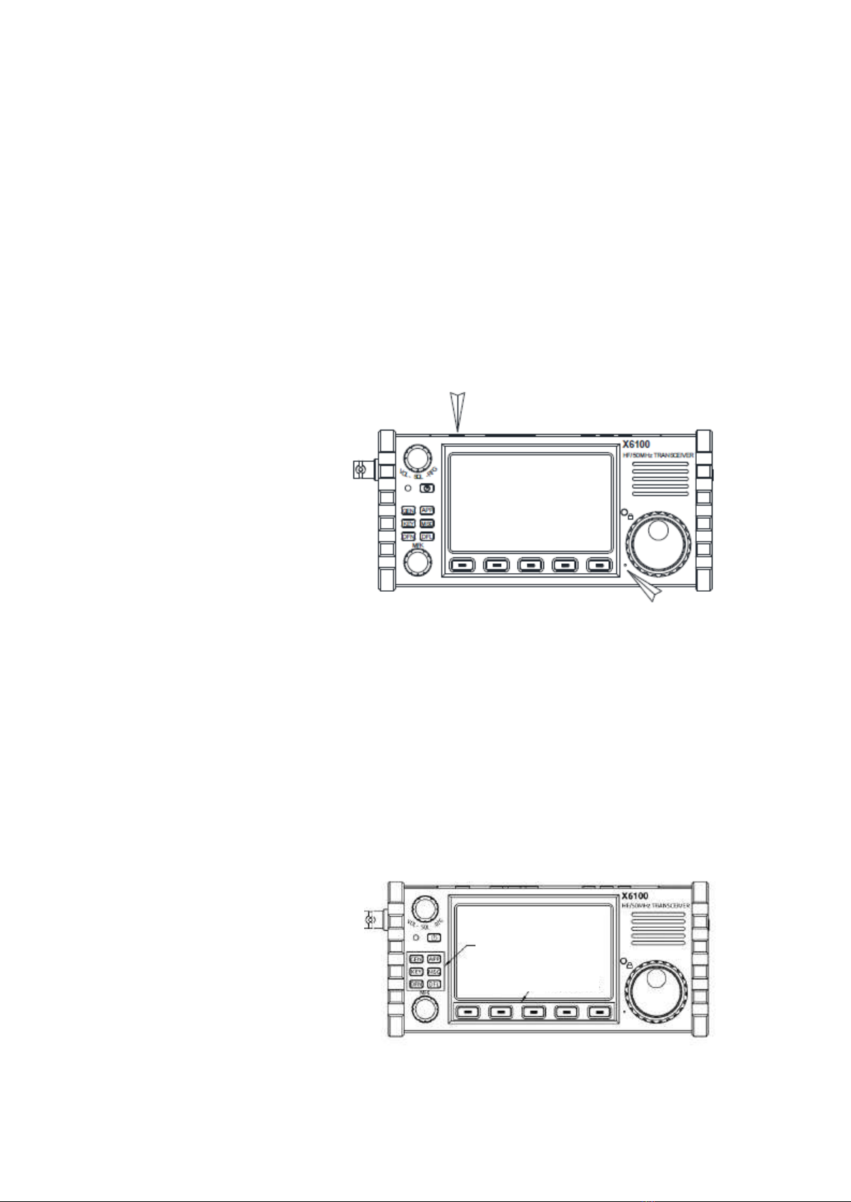
Multifunctional operation
Operation methods:
1. Function buttons in the left
area of the panel can directly
access the common function
operation menu.
2. After selecting a direct
button, the corresponding menu
will appear at the bottom of the
screen. Press the corresponding
button below to operate the
function.
Directly access to
functional button area
Multifunctional
button area

16
3. After selecting a function, rotate the large knob to adjust the corresponding parameter
values. Adjustment parameters are displayed in the red character section in the
function menu tag.
--------------------------------------------------------------------------------------------------------
KEY function settings and operation
Short press [KEY] to enter the menu of KEY items. The KEY menu will appear at the
bottom of the screen:
Page1:
KEY TYPE
KEY SPEED
IAMBIC
TONE
TONE LEVEL
Page2:
QSK TIME
DI/DA RATIO
CW TRAINER
KEY TYPE: manual/automatic mode settings
KEY SPEED: automatic key bit rate settings
IAMBIC: Iambic A/B mode settings
TONE: sidetone frequency settings
TONE LEVEL: sidetone volume settings
QSK Time: QSK time setting
DI/DA RATIO: automatic key dot-and-dash interval proportion settings
CW TRAINER: CW learning mode switch
MSG function setting and operation
Short press [MSG] to enter the menu of MSG items. The KEY menu will appear at the
bottom of the screen: Page1:
MGS 1
MGS 2
MGS 3
MGS 4
MGS 5
This function aims to pre-store edited information and is used to automatic transmission
function.
DFN function setting and operation
Short press [DFN] to enter the menu of DFN items. The KEY menu will appear at the
bottom of the screen:
Page1:
NR
NR DEPTH
NB
NB WIDTH
NB LEVEL
Page2:
DNF
DNF CENTER
DNF WIDTH
17
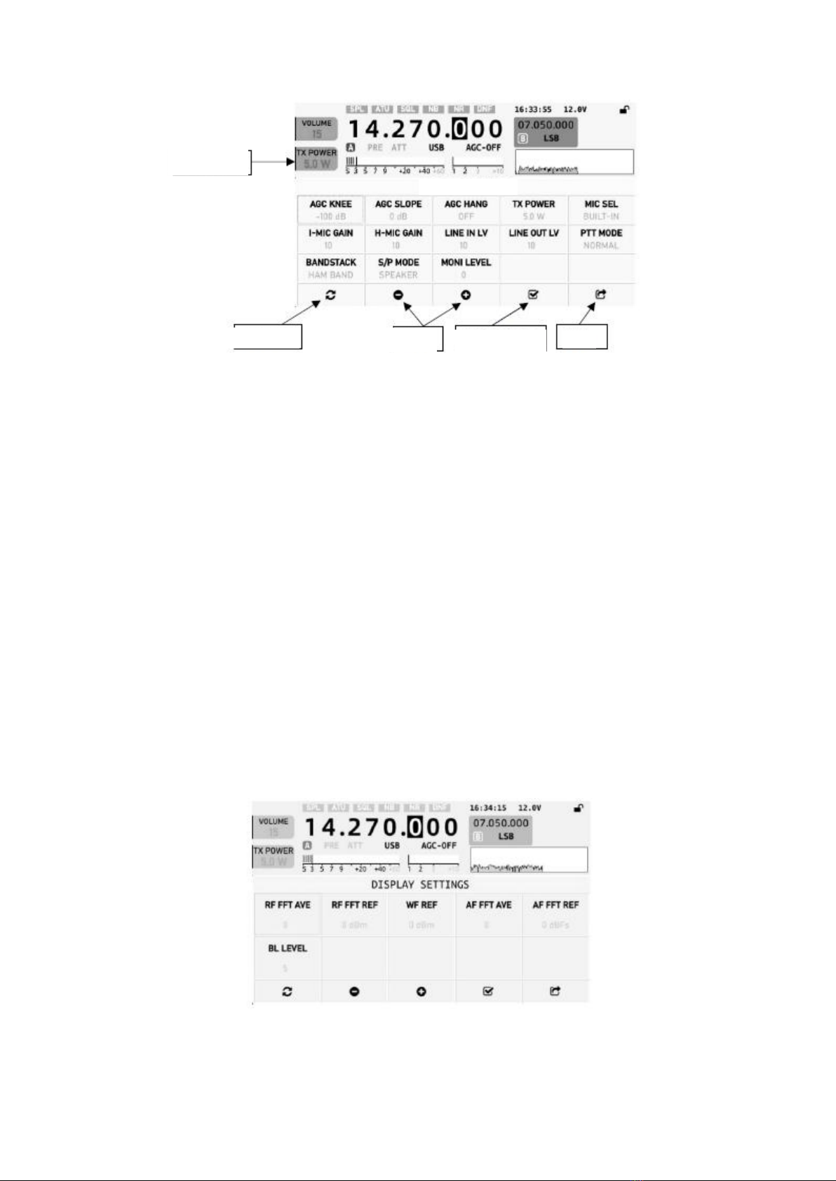
AGC KNEE: AGC control level
AGC SLOPE: AGC control slope
AGC HANG: AGC remaining settings
TX POWER: transmitting power setting s
MIC SEL: microphone selection (body/hand microphone)
I-MIC GAIN: Built-in microphone gain settings
H-MIN GAIN: hand microphone gain settings LINEINLV: line input signal level
settings
LINE OUT LV: line output level settings
PTT MODE: PTT mode settings
BANDSTACK: band group display mode (amateur band/full band only)
S/PMODE: headphone port output selection (headphone/external loudspeaker)
MONI LEVEL: monitoring level settings
DISPLAY SETTINGS: display settings menu
RF FFT AVE: settings of displayed average of radio frequency spectrum
RF FFT REF: settings of displayed reference level of radio frequency spectrum
Shortcut tag
Exit
Restore default
Adjustment
Set as shortcut
tag
18
WF REF: waterfall plot reference offset level
AF FFT AVE: settings of displayed average of audio spectrum
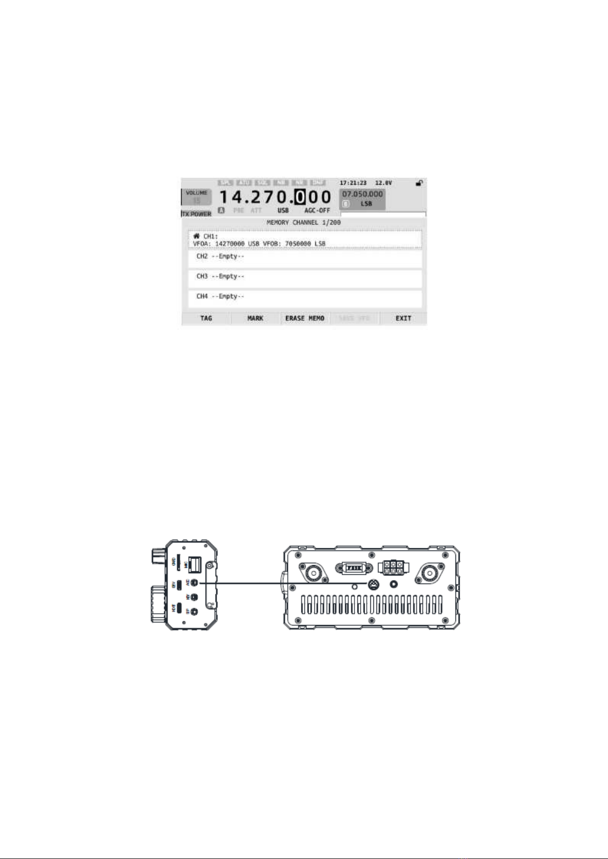
TAG: edit tag
MARK: star mark
ERASEMEMO: delete current channel memory
SAVEVF0: store current VF0 settings into channels
EXIT: exit
Note :
SAVEVF0 button is invalid if current channel is not empty. Press ERASEMEMO
button first to delete current memory before re-storage.
Appendix 1
Connection between X6100 and XPA125B (L4001 cable)
L4001 cable
■ XPA125B power amplifier and L4001 cable need to be separately ordered.
AF FFT REF: settings of displayed reference level of audio spectrum
BLBL LEVEL: backlight brightness settings
MEMORY EDTT: channel memory editing menu
Parameter & specification
Frequency range: receiving: 0.5MHz~30MHz 50.00~53.99MHz

19
Audio output: 0.4W(8Ω, ≤10%THD)
Audio output impedance: 4~16Q
Antenna tuner
Tuning range of antenna tuner VSWR: 1:5.0
First tuning time: ≤15s
Memory load tuning: ≤0.2s
〇 Above specifications are typical values and subject to change without prior notice.
〇 Working frequency range of transceiver varies from version of the equipment.
Ask local dealer for details.
Packing List
X6100 host: 1 pc.
Type-C cable: 1 pc.
Multifunction hand microphone: 1 pc.
Charger adapter: 1 pc.
Power cable: 1 pc.
Warranty card: 1 pc.
Manual: 1 pc.
Quality certificate: 1 pc.
Table of contents
Other Chongqing Xiegu Technology Transceiver manuals


