Iridium NAL Research Corporation 9602-NAL User manual

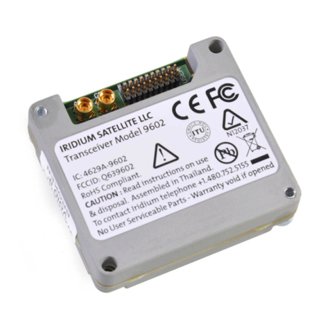
Copyright © 2021 by NAL Research Corporation
11100 Endeavor Ct., Suite 300
Manassas, Virginia 20109 USA
Phone: 703-392-1136
Powered by
9602-NAL User Guide
Version A
March 28, 2022
451-92695-001A

9602-N User Guide Version A
Document Number: 451-92695-001A 2 of 40
LEGAL DISCLAIMER AND CONDITION OF USE
This document contains information for the Iridium 9602-NAL Short Burst Data (SBD)
Transceiver and accompanying accessories (“Product”), which are provided “as is.” Reasonable
effort has been made to make the information in this document reliable and consistent with
specifications, test measurements and other information. However, NAL Research Corporation
and its affiliated companies, directors, officers, employees, agents, trustees or consultants (“NAL
Research”) assume no responsibility for any typographical, technical, content or other
inaccuracies in this document. NAL Research reserves the right in its sole discretion and without
notice to you to change Product specifications and materials and/or revise this document or
withdraw it at any time. User assumes the full risk of using the Product specifications and any
other information provided.
NAL Research makes no representations, guarantees, conditions or warranties, either express
or implied, including without limitation, any implied representations, guarantees, conditions or
warranties of merchantability and fitness for a particular purpose, non-infringement, satisfactory
quality, non-interference, accuracy of informational content, or arising from a course of dealing,
law, usage, or trade practice, use, or related to the performance or nonperformance of any
products, accessories, facilities or services or information except as expressly stated in this guide
and/or the Product and/or satellite service documentation. Any other standards of performance,
guarantees, conditions and warranties are hereby expressly excluded and disclaimed to the
fullest extent permitted by the law. This disclaimer and exclusion shall apply even if the express
limited warranty contained in this guide or such documentation fails of its essential purpose.
In no event shall NAL Research be liable, whether in contract or tort or any other legal theory,
including without limitation strict liability, gross negligence or negligence, for any damages in
excess of the purchase price of the Product, including any direct, indirect, incidental, special or
consequential damages of any kind, or loss of revenue or profits, loss of business, loss of privacy,
loss of use, loss of time or inconvenience, loss of information or data, software or applications or
other financial loss caused by the Product (including hardware, software and/or firmware) and/or
the Iridium satellite, or arising out of or in connection with the ability or inability to use the
Product (including hardware, software and/or firmware) and/or the Iridium satellite to the fullest
extent these damages may be disclaimed by law and whether advised of the possibilities of such
damages. NAL Research is not liable for any claim made by a third party or made by you for a
third party.
9602-N User Guide Version A
Document Number: 451-92695-001A 3 of 40
REVISION HISTORY
Revision
Date
Description
Author
1.0.1
02/25/2013
Initial version
A. Schiltz
A
03/28/2022
- Updated to new template; editorial update.
- Formal release
A. Schiltz,
A. Nguyen

9602-N User Guide Version A
Document Number: 451-92695-001A 4 of 40
REFERENCE DOCUMENTS
The latest revisions of the NAL documents are available from the NAL Research website at
https://www.nalresearch.com/support/documentation-downloads/.
Reference
Title
Revision/Date
[1]
Product Information Model 9602-N
2019
[2]
AT Commands for Models 9602 (TN2010-111-V1.0)
Version 1.0, 2010
[3]
SatTerm Software Manual (TN2009-19-V7.0)
Version 8.9.7, 2022
[4]
Additional Information on DirectIP SBD (TN2007-637-
V1.0)
Version 1.0 2009
[5]
Additional Information on SBD (AN2007-07-V3.3.0)
Version 3.3 2009

9602-N User Guide Version A
Document Number: 451-92695-001A 5 of 40
TABLE OF CONTENTS
1Introduction................................................................................................................. 9
2Mechanical Interfaces ................................................................................................ 10
3Multi-Interface Connector.......................................................................................... 11
3.1 RS232 Data Interface (9-Wire Configuration)..................................................................... 11
3.2 RS232 Data Interface (3-Wire Configuration)..................................................................... 12
3.3 DC Power Interface............................................................................................................. 12
3.4 Power On/Off Control......................................................................................................... 14
3.5 DC Supply Indicator Output ................................................................................................ 15
3.6 Network Availability Output ............................................................................................... 15
3.7 S-Meter Performance ......................................................................................................... 16
4Iridium Antenna Connector ........................................................................................ 17
5GPS Pass-Through ...................................................................................................... 19
6Configuration Settings................................................................................................ 21
7Modes of Operations ................................................................................................. 22
8Hardware Failure Reporting ....................................................................................... 23
9Technical Support ...................................................................................................... 24
Appendix A: Power Consumption of the 9602-NAL............................................................... 25
Appendix B: Standards Compliance...................................................................................... 29
Appendix C: Export Compliance........................................................................................... 30
Appendix D: The Iridium Network........................................................................................ 31
Iridium Network Data Capabilities................................................................................................ 32
Dial-up Data Service...................................................................................................................... 33
Direct Internet Connection ........................................................................................................... 35
Short Burst Data............................................................................................................................ 36
Short Messaging Service............................................................................................................... 36
RUDICS .......................................................................................................................................... 37
Iridium Geolocation ...................................................................................................................... 37
Appendix E: Design Specifications........................................................................................ 38
Mechanical Specifications............................................................................................................. 38
RF Specifications ........................................................................................................................... 38
Radio Characteristics..................................................................................................................... 38

9602-N User Guide Version A
Document Number: 451-92695-001A 6 of 40
Electrical Specifications................................................................................................................. 38
Environmental Specifications ....................................................................................................... 39
Data I/O Specifications.................................................................................................................. 39
Appendix F: Mechanical Drawing......................................................................................... 40
TABLE OF FIGURES
Figure 1: Iridium 9602-NAL Connectors........................................................................................ 10
Figure 2: Power Input Settings...................................................................................................... 13
Figure 3: Model HRC-24-11 Data/Power Cable Assembly............................................................ 14
Figure 4: External ON/OFF Setting for the 9602-NAL................................................................... 15
Figure 5: SYN7391-C Antenna....................................................................................................... 17
Figure 6: GPS Path When 9602-NAL is Not Transmitting and GPS is Active................................. 20
Figure 7: In-rush Current Spike During Power-up (6 VDC Input).................................................. 26
Figure 8: In-rush Current Spike During Power-up......................................................................... 26
Figure 9: Current Drawn During Standby...................................................................................... 27
Figure 10: Current Drawn During SBD .......................................................................................... 27
Figure 11: Current Drawn During Sleep........................................................................................ 28
Figure 12: Iridium Network Major Components .......................................................................... 31
Figure 13: Iridium Network Data Capabilities............................................................................... 33
Figure 14: PSTN Dial-up Connectivity ........................................................................................... 34
Figure 15: Iridium Dial-up Data Service ........................................................................................ 35
Figure 16: 9602-NAL Mechanical Drawing.................................................................................... 40
TABLE OF TABLES
Table 1: Pin Assignments for the Multi-interface Connector....................................................... 11
Table 2: Antenna Characteristics Required .................................................................................. 17
Table 3: Custom Antenna Characteristics Required ..................................................................... 18
Table 4: Regulatory and Technical Certifications ......................................................................... 29

9602-N User Guide Version A
Document Number: 451-92695-001A 7 of 40
GLOSSARY
AT ...............................Attention. Two-letter sequence starting a string of terminal commands.
The AT is intended to get the terminal’s attention prior to executing a
command.
BIS ..............................Bureau of Industry and Security
CE ...............................Conformité Européenne
CTS..............................Clear To Send
DAV ............................Data After Voice
DC...............................Direct Current
DCD ............................Data Carrier Detect
DoD ............................Department of Defense
DSN.............................Defense Switch Network
DSR.............................Data Set Ready
DTE .............................Data Terminal Equipment
EAR.............................Export Administration Regulations
EMI .............................Electromagnetic Interference
EMSS ..........................Enhanced Mobile Satellite Services
ETSI.............................European Telecommunications Standards Institute
FCC .............................Federal Communications Commission
FDMA .........................Frequency-Division Multiple Access
GND............................Ground
GPS.............................Global Positioning System
GSM............................Global System for Mobile Communications
I/O ..............................Input/Output
IP ................................Internet Protocol
ISU ..............................Iridium Subscriber Unit
kbps............................Kilobits Per Second
LAN.............................Local Area Network
LED .............................Light-Emitting Diode
LNA.............................Low-Noise Amplifier

9602-N User Guide Version A
Document Number: 451-92695-001A 8 of 40
MT-SBD ......................Mobile-Terminated Short-Burst Data
NIPRNet......................Non-classified Internet Protocol Router Network
OFAC...........................Office of Foreign Asset Controls
PDA.............................Personal Digital Assistant
PPP .............................Point-To-Point Protocol
PSTN...........................Public Switched Telephone Network
PWR............................Power
RI ................................Ring Indicator
RF................................Radio Frequency
RHCP...........................Right-Handed Circular Polarization
RTS..............................Request To Send
RUDICS .......................Router-Based Unrestricted Digital Internetworking Connectivity Solution
RX ...............................Receiving
SatTerm......................Satellite Terminal Emulator Software
SBD.............................Short-Burst Data
SIM .............................Subscriber Identification Module
SMA............................SubMiniature version A (RF connector)
SMS ............................Short Message Service
TCP .............................Transmission Control Protocol
TDD.............................Time-Division Duplex
TDMA .........................Time-Division Multiple Access
TX ...............................Transmitting
VDC.............................Volts (direct current)
VSWR..........................Voltage Standing Wave Ratio

9602-N User Guide Version A
Document Number: 451-92695-001A 9 of 40
1INTRODUCTION
This document describes the operational features, configuration settings, and electrical and
mechanical interfaces of the 9602-NAL. The 9602-NAL modem is a satellite transceiver
comprising an Iridium 9602 transceiver with an extended input voltage range, and only allows
Short Burst Data (SBD connectivity to the Iridium satellite network. It does not support voice,
circuit-switched data, or Short Message Service (SMS). Similar to a standard landline modem,
the 9602-NAL can be controlled by any Data Terminal Equipment (DTE) capable of sending
standard AT commands via an RS232 serial port. A DTE can be a desktop computer, a laptop
computer, a PDA, or even a microcontroller. NAL Research can enable the 9602-NAL to utilize
either the Iridium commercial gateway or the DoD EMSS Gateway when requested by an
authorized user. Key features of the 9602-NAL include:
Does not incorporate nor need a SIM card to operate
Has an automatic notification indicating a message is queued at the gateway
Provides a maximum Mobile-Originated (MO) message size of 340 bytes
Provides a maximum Mobile-Terminated (MT) message size of 270 bytes
Supports RS232 serial connection
Capable of voltage range from 5 VDC to 32 VDC
IMPORTANT: An EMSS-enabled 9602-NAL must first be provisioned (signed up for airtime) with
EMSS SBD service before testing or field use. Accessing the Department of Defense (DoD)
Enhanced Mobile Satellite Services (EMSS) Gateway is not authorized until the 9602-NAL is
provisioned. Unauthorized attempts to access the DoD EMSS Gateway will result in immediate
disabling of the offending device, which must then be returned to NAL Research for repair. See
https://sbd.pac.disa.mil for more information regarding EMSS service provisioning. Note: This is
a U.S. Government Information System website, and can only be accessed by authorized users
with a valid certificate.

9602-N User Guide Version A
Document Number: 451-92695-001A 10 of 40
2MECHANICAL INTERFACES
The 9602-NAL is intended to be used as a modem connected to a DTE via an RS232 serial
interface. The 9602-NAL incorporates two different connectors—a multi-interface connector
and a SubMiniature version A (SMA) Iridium antenna connector—as shown in Figure 1. When
requested, an SMA Global Positioning System (GPS) pass-through connector can be installed as
an option (see section 5). The 9602-NAL is provided with four mounting holes, one at each
corner. It is recommended to use 6-32 screws to fasten the modem down.
Figure 1: Iridium 9602-NAL Connectors
Multi-Interface Connector
Iridium Antenna Connector

9602-N User Guide Version A
Document Number: 451-92695-001A 11 of 40
3MULTI-INTERFACE CONNECTOR
The multi-interface connector is a male 15-pin miniature D-Sub type (DB-15 connector) that
includes five interfaces—DC power input, power on/off control, RS232 data interface, network
availability output, and supply power indicator output. Individual pin assignments are
summarized in Table 1.
Table 1: Pin Assignments for the Multi-interface Connector
Pin #
Signal
Description
Interface
1
EXT_PWR
External DC Power Input
+5.0 VDC ±0.5 V
2
EXT_PWR
External DC Power Input
+6.5 VDC to
+32 VDC
3
EXT_GND
External GND Input
0 V
4
ON/OFF
ON/OFF Control Input; ON ≥2.0 V; OFF ≤0.5 V
Analog
5
SUPPLY_OUT
Supply Power Indicator Output
+3.3 V, 5 mA Max.
6
S_TX
RS232 Transmit Data Input
RS232 Data
7
S_RX
RS232 Receive Data Output
RS232 Data
8
SIG_GND
Signal Ground, 0 V Signal Reference and Return
0 V
9
DCD
RS232 Data Carrier Detect Output
RS232 Data
10
DSR
RS232 Data Set Ready Output
RS232 Data
11
CTS
RS232 Clear To Send Output
RS232 Data
12
RI
RS232 Ring Indicator Output
RS232 Data
13
RTS
RS232 Request To Send Input
RS232 Data
14
DTR
RS232 Request To Send Input
RS232 Data
15
NET AVAIL
Network Availability; Avail=High, Not Avail=Low
3.3 V Digital
3.1 RS232 DATA INTERFACE (9-WIRE CONFIGURATION)
The 9602-NAL supports a standard RS232 serial interface to a host system DTE incorporating
hardware handshaking and flow control. The RS232 interface comprises eight signals and a
ground, as shown in Table 1. The RS232 interface allows a connected DTE to utilize the 9602-
NAL’s functionality through AT commands. Note that the ring indicator is used by the 9602-NAL
to indicate that a Mobile-Terminated SBD (MT-SBD) message is queued at the gateway. The

9602-N User Guide Version A
Document Number: 451-92695-001A 12 of 40
DTE can monitor this pin and use appropriate AT commands to retrieve the MT-SBD message.
The 9602-NAL does not support autobaud. Set the baud using the AT+IPR command. The
factory-set baud is 19.2 kbps.
3.2 RS232 DATA INTERFACE (3-WIRE CONFIGURATION)
The 9602-NAL’s RS232 interface operates as a 9-wire connection and it is a recommended
configuration. However, the 9602-NAL may also be operated with a 3-wire connection, where
only transmit, receive, and ground signals are used with no flow control. Several steps must be
taken to allow 3-wire configuration. These steps ensure the 9602-NAL and DTE work together
without hardware handshaking.
1. Set AT&Dn to AT&D0 to ignore the DTR input.
2. Set AT&Kn to AT&K0 to disable RTS/CTS flow control.
3. The other output signals may be connected and operate as follows:
a. CTS driven ON (low).
b. DSR operates as normal.
c. RI operates as normal.
d. DCD driven ON (low).
NOTE: The Request To Send / Clear To Send (RTS/CTS) flow control when enabled, is only used
when the data port is in SBD data mode. In AT command mode, RTS is ignored and CTS is driven
ON (low).
3.3 DC POWER INTERFACE
The DC power interface comprises two DC power inputs, a ground input, and a control signal, as
summarized in Table 1. The 9602-NAL accepts either +5 VDC input through pin #1 or +6.5 VDC
to +32 VDC input through pin #2. The 9602-NAL is shipped with hardware set for +5 VDC input.
It can be changed to +6.5 VDC to +32 VDC input through an internal jumper. Remove the
modem’s top plate to find the jumper. With the 9602-NAL held in the position shown in Figure
2(DB-15 connector on the left side and SMA antenna connector on the right side), the 9602-
NAL is set for +5 VDC when the jumper is on the left pin, and it is set for +6.5 VDC to +32 VDC

9602-N User Guide Version A
Document Number: 451-92695-001A 13 of 40
when the jumper is on the right pin. Both power pins on the multi-interface connector and their
corresponding voltage settings on the jumper must be used for the unit to power up properly.
Figure 2: Power Input Settings
IMPORTANT: You can remove the 9602-NAL’s top plate to set the jumper but not for repair or
services. The warranty is voided if the 9602-NAL is disassembled for any reason other than to
set the jumper.
Plots of DC power requirements for the 9602-NAL are in Appendix A: Power Consumption of
the . In addition, the power supply must also guarantee the following:
The supply voltage drops for an 8.3 ms burst is not more than 0.2 V.
The power supply provides overcurrent protection in case of device malfunction.
The supply noise is less than the limits in the following profile:
o100 mV peak-to-peak from 0 to 50 kHz
o5 mV peak-to-peak at 1 MHz measured in 50 kHz bandwidth
o10 mV peak-to-peak at 1 MHz measured in 1 MHz bandwidth
o5 mV peak-to-peak above 5 MHz measured in 1 MHz bandwidth
Keep cables used to supply power to the 9602-NAL as short as possible to prevent significant
voltage drop, which can cause the 9602-NAL to malfunction during an SBD session.
Model HRC-24-11 is a data/power cable assembly designed to work with the 9602-NAL modem.
The HRC-24-11 has a three-foot RS-232 cable for connection onto a computer and two wires for
DC power input to a 9602-NAL. Model HRC-24-12 is available on the NAL website
(www.nalresearch.com)
Jumper used to
set input
voltage range

9602-N User Guide Version A
Document Number: 451-92695-001A 14 of 40
Figure 3: Model HRC-24-11 Data/Power Cable Assembly
Power reset by the 9602-NAL during an SBD session indicates the power source is unable to
sustain required peak current demand.
3.4 POWER ON/OFF CONTROL
The 9602-NAL is shipped with hardware set for automatic startup when power is applied,
whether the voltage setting is for +5 VDC or for +6.5 VDC to +32 VDC. As long as the input
voltage is applied, an internal logic high on pin #4 turns on the 9602-NAL, ignoring the external
voltage input to this pin.
If external ON/OFF control is required, pin #4 on the multi-interface connector can be set to
accept an external analog signal (ON>=2.0V; OFF<=0.5V) to turn a powered 9602-NAL on and
off, bypassing the internal controller.
When pin #4 is pulled to GND level (i.e., below 0.5 V), the powered 9602-NAL will be in
the off state.
When it is pulled to HIGH level (i.e., above 2.0 V but not to exceed 5 V), the powered
9602-NAL will be in the on state. The current drawn on the external load used to pull the
9602-NAL to HIGH is no more than 0.5 mA.
The internal ON/OFF controller can be disconnected by turning the internal rotary switch
counterclockwise. The switch can be found by removing the modem’s top plate. With the 9602-
NAL held in the position shown in Figure 4 (DB15 connector on the left and SMA antenna
connector on the right), the 9602-NAL is set for internal ON/OFF when the groove on the rotary
switch is in the ‘\’ position and is set for external ON/OFF when the grove on the rotary switch

9602-N User Guide Version A
Document Number: 451-92695-001A 15 of 40
is in the ‘/’ position. A flathead screw driver can be used to turn the rotary switch to toggle
between the two settings.
Figure 4: External ON/OFF Setting for the 9602-NAL
Prior to turning off the 9602-NAL, issue a “flush memory” (AT*F) command to ensure all
memory-write activity is completed. When a 9602-NAL has been turned off, wait until power
has reached 0 V, and then wait more than 2 seconds before reapplying power to a unit.
Additionally, if a unit does not respond to AT commands, power off the module, wait 2 seconds,
and then power it back on. When a 9602-NAL is powered off, the power-on reset circuit
requires 2 seconds for voltages to decay. If the 2-second wait time is not adhered to, the reset
circuit may not operate and the 9602-NAL could be placed in a non-operational state. The state
is not permanent and can be rectified by the above procedure.
3.5 DC SUPPLY INDICATOR OUTPUT
A DC supply indicator signal is provided by the 9602-NAL on pin #5, which could be used directly
for driving an LED to provide a visible indication that the 9602-NAL supply is on. Alternatively,
the output signal could be used in application logic to determine whether the internal 9602-
NAL power supply is on.
3.6 NETWORK AVAILABILITY OUTPUT
The digital output of pin #15 can be used to determine when the 9602-NAL has visibility to the
Iridium satellite network or the Iridium network is “available.”Network Available means that
the 9602-NAL can successfully receive the Ring Channel, or, put more simply, it can see an
Iridium satellite. Network Available is not a guarantee that a message is successfully sent. The
Network Available state is evaluated every time the Ring Channel is received or missed. If the
Ring Channel is visible, then it is updated every four seconds. If the Ring Channel is not
Rotary switch used
to set power on/off
control

9602-N User Guide Version A
Document Number: 451-92695-001A 16 of 40
currently visible, then the update period can be as long as two minutes, depending on how long
the lack of satellite visibility existed. This is because the 9602-NAL attempts to conserve power
by increasing the ring-search interval while the satellites are not visible. Every time a ring search
fails, the time to wait is increased until it reaches a limit at 120 seconds. The wait time between
search windows is reset to 4 seconds every time a search succeeds.
If Network Available is currently off, you may still attempt an SBDI[X] session. This will force the
9602-NAL to look for the Ring Channel immediately, and on finding it, to attempt to send the
message. In this case, Network Available will not come on immediately. Network Available does
not turn on while in a +SBDI session. It will, however, turn on 4 seconds later, assuming that the
Ring Channel is present. After the SBD session completes, the 9602-NAL performs a new Ring
Channel search sequence, at the end of which Network Available gets turned on. That can take
between 4 and 12 seconds. If the +SBDI attempt fails to find the ring channel, the search
window does not reset to 4 seconds. Note that the behavior of +CIEV:1 is identical to that of the
Network Available output.
3.7 S-METER PERFORMANCE
The S-meter readings reported over the AT command interface indicate the signal strength of a
9602-NAL. Be careful when using the S-meter readings for comparisons between devices. Of
particular note are the following:
1. There is a 0.5 dB tolerance on calibrating the S-meter.
2. Each signal strength bar represents a 2 dB increment.
3. Multiple ring channels can be present at the same time, so units can lock to different
signals.
4. If the reading is near the decision threshold, it would be easy to see a 1-bar difference.

9602-N User Guide Version A
Document Number: 451-92695-001A 17 of 40
4IRIDIUM ANTENNA CONNECTOR
The 9602-NAL uses a single SMA female 50-ohm antenna connector to both transmit and
receive. The mating SMA male connectors are readily available from many RF hardware
providers. Cable loss between the 9602-NAL and the antenna is critical and must be kept to less
than 3 dB at the operating frequency of 1616 to 1626.5 MHz. Implementation loss higher than
this will affect the Iridium link performance and quality of service. Connect the 9602-NAL to an
antenna with the characteristics shown in Table 2.
Table 2: Antenna Characteristics Required
Parameter
Value
Input/Output Impedance
50 ohms nominal
Gain
3 dBi
Polarization
Right-handed circular polarization (RHCP)
VSWR (Maximum Operational)
1.5 to 1
NAL Research offers several types of antennas for use with the 9602-NAL. These antennas
include the fixed mast, mobile magnetic/permanent mount, and portable auxiliary. For low cost
and applications where small form factor and light weight are required, NAL Research highly
recommends model SYN7391-C (see Figure 5). Model SYN7391-C is a small, inexpensive L-
band antenna designed to operate with NAL Research satellite modems and trackers. It is
optimized to operate under various data modes, specifically SBD.
Figure 5: SYN7391-C Antenna

9602-N User Guide Version A
Document Number: 451-92695-001A 18 of 40
If the specific application requires a custom antenna, it must meet the following characteristics
in Table 3.
Table 3: Custom Antenna Characteristics Required
Parameter
Value
Operating Temperature Range
–40°C/+85°C without loss of function
Measurement Frequency Range
1616 to 1626.5 MHz
Return Loss (Minimum)
9.5 dB (<1.5:1 VSWR)
Gain
0.0 dBic (weighted average minimum)
Minimum ‘Horizon’ Gain
–2.0 dBic (82° conic average)
Nominal Impedance
50 ohms
Polarization
Right-handed circular polarization (RHCP)
Basic Pattern
Omnidirectional and hemispherical

9602-N User Guide Version A
Document Number: 451-92695-001A 19 of 40
5GPS PASS-THROUGH
As an option, a second SMA connector can be installed by NAL Research on the 9602-NAL to be
used as a pass-through connection from the Iridium antenna path. It is provided for GPS
receivers with the ability to share the Iridium antenna. An overview of this circuit is provided in
Figure 6. Select a wideband Iridium antenna with appropriate sensitivity in both the Iridium
frequency and the GPS frequency. The 9602-NAL allows for GPS signals to pass at all times
except during Iridium transmitter burst. This protects the GPS receiver from an electric
overstress condition with a minimum impact on the GPS reception and functionality. However,
the Iridium signal CANNOT be totally isolated. During the SBD transmit burst, there will be
leakage of the 1616 to 1626 MHz to the GPS port, which can significantly degrade the quality of
the GPS signals. Appropriate Surface Acoustic Wave (SAW) filters must be implemented in the
front end of the GPS receiver. The GPS pass-through SMA connector must be terminated with a
50 Ωload when not in use. A suitable load is the Huber+Suhner 65_SMA-50-0-1/111_NE or
equivalent.
The GPS pass-through can be turned on by applying a 1.2 VDC threshold to the GPS SMA
connector. The DC bias on the GPS antenna connector is similar to having an active GPS
antenna. In normal operation, this bias would be used to power the LNA inside the active
antenna. For the Iridium 9602-NAL, the bias voltage is used to activate an RF switch and enable
connection of the GPS port to the antenna port. With external power applied and the 9602-NAL
off, the GPS path is still available for use. A DC voltage on the GPS connector activates the LNA
in the 9602-NAL, and the 9602-NAL draws approximately 10 mA from the 9602-NAL supply.
With external power applied and the 9602-NAL inactive, and the GPS path not enabled, the
quiescent current consumption will be less than 0.5 mA.

9602-N User Guide Version A
Document Number: 451-92695-001A 20 of 40
Figure 6: GPS Path When 9602-NAL is Not Transmitting and GPS is Active
Note the following operational points when using the GPS receivers connected to the
pass-through GPS SMA connector:
The GPS pass-through path is activated by detecting the presence of a DC voltage on
the center pin of the GPS connector. The 9602-NAL uses the voltage from the GPS
center pin to switch on the RX path and requires minimal current of less than 100 μA.
The GPS path is activated when this center-pin voltage is higher than 1.2 V.
There is a path loss of approximately 3 dB in the receive direction from Iridium SMA
connector to the GPS SMA connector.
The GPS receive path is temporarily switched off during transmissions from the 9602-
NAL.
As long as power supply to the 9602-NAL is connected and the DC voltage on the GPS
connector is present, the GPS pass-through path is made available. The GPS path is
available even when the 9602-NAL has been turned off using its on/off control signal.
The GPS receiver must present 50 Ωimpedance across the Iridium band or SBD
performance could be degraded.
The output return loss is typically –8 dB.
Table of contents
Other Iridium Transceiver manuals

Iridium
Iridium 9522A Technical manual

Iridium
Iridium SBD9602 Instruction Manual

Iridium
Iridium 9603 Instruction Manual

Iridium
Iridium 9523 User manual

Iridium
Iridium 9601 User manual

Iridium
Iridium 9602 User manual

Iridium
Iridium 9522A User manual

Iridium
Iridium 9522B Installation and operation manual

Iridium
Iridium 9601 Instruction Manual

Iridium
Iridium Certus 9770 User manual