CHOWEL WELCOM 600P User manual

OM-W600P-0410(E)
RESISTANCE WELDING CONTROLLER
WELCOM 600P
USER MANUAL
CHOWEL CORPORATION

WELCOM 600P
CHOWEL CORPORATION - 1 -
Please, read carefully this manual for safe
and efficient use of the welding controller
The information in this manual is the possession of the chowel, it is subject to change without notice.
And this manual can be changed also without the notice.
CHOWEL is registered trademark of the CHOWEL CORPORATION.
CHOWEL FIRST FACTORY
395-3 MOKNAE-DONG, DANWON-GU
ANSAN-CITY, GYEONGGI-DO, KOREA
TEL 82-31-494-2511
FAX 82-31-495-2515
CHOWEL SECONDARY FACTORY
598 SUNGGOK-DONG, DANWON-GU
ANSAN-CITY, GYEONGGI-DO, KOREA
TEL 82-31-493-9911
FAX 82-31-495-2518
COPYRIGHT CHOWEL CORPORATION ©2002
FIRST PRINTING, February, 2003
PRINTED IN REPUBLIC OF KOREA
WELCOM 600P
CHOWEL CORPORATION - 2 -
IMPORTANT
Read first this manual before operate this welding controller. In some case, failure to follow the
instructions manual can lead to control or machine damage. In other cases failure to follow
instructions can lead to injury, or death of personnel.
This manual explains some instructions depends on the level of danger as follows.
DANGER
If shows readers where people will be hurt if procedures are not followed properly.
WARNING
If shows readers where people may be hurt if procedures are not followed properly
CAUTION
If shows readers where machinery may be damaged or economic loss can occur, or
people may be hurt if procedures are not followed properly.
RISK OF ELECTRIC SHOCK
It shows readers where people will be struck by an electric shock if procedures are not
followed properly.
WELCOM 600P
CHOWEL CORPORATION - 3 -
READ FIRST
To use this welding controller in safety, the operator should follow industry standards and safety
senses whenever working on, or near the weld machine.
In some case, failure to follow the warning instruction can lead to control or machine damage. In other
cases failure to follow these instruction can lea to injury, or death of personnel. Some examples of safe
practices are listed below. These examples are not to be considered a comprehensive listing of safety
practices. Always use safety senses when working with any type of machinery.
DANGER
During electrical power is ON, this welding controller is charged with high voltage electricity. Turn
electrical power OFF before open the door.
In the case the door is opened as it is not turn OFF can lead to injury by an electric shock, or death of
personnel.
WARNING
In some case failure to follow these instructions as follows can lead to control damage or injury of
personnel.
Ensure that control / machine is connected to the correct voltage before turning electrical power ON.
Whenever power is ON, stand clear of moving parts. This practice should be used even if the
machine is not actually in use.
Before turning electrical power OFF, ensure that personnel are standing clear of moving parts that
are pneumatic or hydraulic powered.
Whenever electrical power is turned OFF, install a “lock-out” device at the main disconnect to
prevent power from being accidentally turned ON.

WELCOM 600P
CHOWEL CORPORATION - 4 -
CAUTION
Turn electrical power OFF before changing the tap switch at the weld transformer.
In the case failure to follow the instruction like a welding at changing the tap switch can lead to injury
to personnel.
Turn stop cock OFF before some piping work.
In the case failure to follow the instruction like the electrical circuit is splashed with cooling water can
lead to control damage.
CAUTION
Magnetic fileds
It should be borne in mind that welding machine generates intense magnetic fields.
Consequently, “Do not approach the secondary circuit” of the machine carrying on your person any
article that are likely to suffer damage. These include the following:
Any kind of magnetic card or badge, for example credit card, bank card, magnetic strip telephone card,
personal recognition cards, magnetic clocking-on cards, company permits, passes, etc.
Any kind of magnetic tape or media, for example cassette, video cassette, floppy disk, etc.
Any kind of delicate mechanism, for example electronic calculators, cameras, motion picture cameras,
television cameras, watches (especially mechanically driven ones).

WELCOM 600P
CHOWEL CORPORATION - 5 -
CONTENTS
Chapter 1. Installation of welder
§1. Cooling water handling .............................................................................................. 9
§2. Connection of power source and welding transformer ................................................ 10
§3. External I/O signal ..................................................................................................... 11
§4. Pilot input of binary method ....................................................................................... 16
Chapter 2. Programming
§1. Common program ...................................................................................................... 18
§2. Program for each pilot schedule number ..................................................................... 20
§3. Stepper program for each valve schedule number ....................................................... 23
Chapter 3. Indicator and Monitor data
§1. Panel indicator of I/O signal ....................................................................................... 25
§2. Monitor of internal data .............................................................................................. 28
Chapter 4. Fault detection
§1. Fault detection items .................................................................................................. 30
§2. Fault history ............................................................................................................... 33
Chapter 5. Special functions and usage
§1. Stepper control function ............................................................................................. 34
§2. Secondary cable break predict function ...................................................................... 36
§3. External input pilot .................................................................................................... 37

WELCOM 600P
CHOWEL CORPORATION - 6 -
Chapter 6. Operation sequence
§1. Basic operation sequence ........................................................................................... 40
§2. Fault, warning output sequence .................................................................................. 46
§3. Fault reset by pilot sequence ...................................................................................... 48
§4. Reweld at fault sequence ............................................................................................ 49
§5. Weld complete sequence at reset ................................................................................ 49
Chapter 7. DATA input and monitoring
§1. The normal window ................................................................................................... 51
§2. The fault window ....................................................................................................... 53
§3. Function select mode ................................................................................................. 53
Chapter 8. Troubleshooting
§1. External I/O checking ................................................................................................ 60
§2. Program checking ...................................................................................................... 63
Chapter 9. Exceptation
§1. Monitor content ......................................................................................................... 65
Reference
1. WELCOM 600P FAULT CODE TABLE ..................................................................... 67
2. WELCOM 600P DATA SHEET .................................................................................. 68
3. ELECTRICAL CONNECTION DIAGRAM OF WELCOM 600P ............................... 69
4. OUTSIDE VIEW OF WELDCOM 600P ..................................................................... 70

WELCOM 600P
CHOWEL CORPORATION - 7 -
● Attention, check point before operation and in operation
This control device is careful treatment because it is containing a backup battery internally to maintain
program data and monitor data at a power OFF.
1. Please avoid the place which to need the store of the long term is as follows.
1-1. the place which the high temperature and direct light
1-2. the place which the relative humidity is high
1-3. the place with an inflammable and attack gas
1-4. the place which a humidity change is extreme and the dew is formed
1-5. the place which the impact comes to add with the vibration
2. If disjoint and carry the P.C.B, it is careful about the subject following
2-1. To avoid the break of a backup battery, Do lest it should touch directly to aluimum sheet
2-2. To make lest the IC should be destroyed power-failure, do lest possible hand should touch to the
component of PCB.
2-3. To transport, use a vinyl packing paper to become a static electricity protect processing.
3. Check point before operation
3-1. The each connected part must be connected so that it is strong.
Exmple) a connection list of gift of an each part and a linking part of a cooling and high voltage
system
3-2. Cooling water and compressing air observe at this manual and must maintain so that is regular.
3-3. Remove the impurities of the AIR FILTER inside.
3-4. The change of an input power source is the toe in extreme place so that a welding condition unstable,
the rate of voltage change must link ±10% within.
3-5. The welding transformer installs in near to a power source (the fitness 30m within).
If it is far and goes the size from the transformer because of voltage change is strong and can not get
the setting current, it must do sufficient attention.
3-6. the place to give the equipment the vibration and which a surrounding temperature is over 40℃,a
corrosiveness and exploiveness gas must forbid an absolute install in dangerous place to happen.

WELCOM 600P
CHOWEL CORPORATION - 8 -
4. Check point in operation
4-1. After it confirm the existence over the safety of the equipment and check, must turn a power switch
ON.
4-2. It must provide suitable to a proper form power source to a welding power source.
4-3. It must work in the situation to provide cooling water.
4-4. The source of a compression air must be provided to the pressure to be determined.
4-5. If temperature is lesser than 0℃ the factory in the winter, it have the worry which cooling water
system is damaged, it must remove the cooling water completely to a compression air (a welding task
is completed).
4-6. The temperature of cooling water to be supplied must be lesser than 30℃.
And the cooling water pressure must be over 1kg/㎠ at a flowed-water.
4-7. At the secession from this equipment which is the short while among the task, it must turn a power
switch off.

WELCOM 600P
CHOWEL CORPORATION - 9 -
Chapter 1. Installation of welder
It expresses the sequence of the time to install the resistance welder control device in a task spot. It does not
confirm properly and to prevent the accident not to become the operation, apply necessarily this sequence.
§1.Cooling water handling
1-1. A conduit task
Confirm GUN, secondary cable, welding transformer, inside T/C thyristor cooling water conduit.
1-2. Cooling water flow-examination
Confirm sufficient cooling water givers cooling water flow examination and flows certainly at an each
region.
1-3. A conduit method check
Confirm the time to open shut and the door of the T/C unreasonable it skew to pull did not exist in the
conduit and a conduit fix is not touched at the electrode.
1-4. A seepage check
Many at a high voltage part danger is in the T/C inside, the linking part of conduit when the water
pressure is high, confirm sufficiently the seepage does not happen.
1-5. Flow switch check
In the case which flow switch of a flux checker purpose have been established, it use the
TESTER and do the action check.
1-6. The filth clearence
To prevent the leakage accident after cooling water examination finish, T/C with the inside to the
outside remove cooling water to overflow and remove the the filth to happen among a conduit task.
1-7. The fix of the body
To prevent the accident to be due fall of the body, it is certainly fixed to Bolt the device of the body.

WELCOM 600P
CHOWEL CORPORATION - 10 -
§2.Connection of power source and welding transformer
As it do a cable connection within the body at electric wire terminal, do in the sequence such as there.
2-1. The earth of the body
Earth a control device body certainly to prevent electric leakage accident.
2-2. The connection of transformer
Connect the transformer at the 01 terminal and 03 terminals according to inside the body connection
diagram.
2-3. the connection of power source
Connect the power source at the 01 terminal and 02 terminals according to inside the body connection
diagram.
2-4. the check of the connection
Probably wrong wirings of the connection do not exist or it is unreasonable ggug when have drawn the
cable or tight part does not exist or the clothing did not reach the edge of the support but confirm.

WELCOM 600P
CHOWEL CORPORATION - 11 -
§3. External I/O signal
As it marked function and action of outside connection terminal signal, Connect the wiring sothat you are
suitable to an utility purpose.
3-1. External input signal
All the inputs are designed for contact input.
PILOT INPUT1
The PILOT INPUT 1(BIT 0) signal is binary, initiate the sequence when it is turned from OFF to ON.
The case to be used a single pilot input operates to first welding condition.
Connect the pilot signal of welding sequence.
When not used, keep this signal open.
PILOT INPUT2
The PILOT INPUT 2(BIT 0) signal is binary, initiate the sequence when it is turned from OFF to ON.
The case to be used a single pilot input operates to first welding condition.
Connect the pilot signal of welding sequence.
When not used, keep this signal open.
PILOT INPUT4
The PILOT INPUT 4(BIT 0) signal is binary, initiate the sequence when it is turned from OFF to ON.
The case to be used a single pilot input operates to first welding condition.
Connect the pilot signal of welding sequence.
When not used, keep this signal open.
PILOT INPUT8
The PILOT INPUT 8(BIT 0) signal is binary, initiate the sequence when it is turned from OFF to ON.
The case to be used a single pilot input operates to first welding condition.
Connect the pilot signal of welding sequence.
When not used, keep this signal open.
PILOT INPUT16
The PILOT INPUT 16(BIT 0) signal is binary, initiate the sequence when it is turned from OFF to
ON.
The case to be used a single pilot input operates to first welding condition.
Connect the pilot signal of welding sequence.
When not used, keep this signal open.

WELCOM 600P
CHOWEL CORPORATION - 12 -
WELD ON/OFF INPUT
When this input signal is ON, the operation mode is WELD, and when off, TEST MODE.
In the test mode, if the pilot signal is set at ON, the sequence will be in the self-holding status.
Connect this signal to the weld sequence initiation signal.
When not used, keep signal short-circuited to ON.
EMERGENCY STOP
When this input signal is OFF, even if it is while the sequence is active, the weld time control will
stop immediately and the VALVE OUTPUT will be turned OFF.
Normally, connect this signal to the EMERGENCY STOP signal which is ON.
When not used, keep this signal short-circuited to ON.
COUNT RESET
When this signal is turn ON, only the counter that has completed counting is reset to 0 and the
COUNT UP OUTPUT is turned to OFF.
Note that this signal is neglected while the sequence is active.
Connect this signal to reset the counter.
When not used, keep this signal open.
STEEPER RESET
When this signal is turned ON, the step no. and the step counter are reset and the STEPPER
COMPLETE OUTPUT is turned OFF.
Connect this signal to the signal that resets the stepper.
Note that this signal is neglected while the sequence is active.
When not used, keep this signal open.
FAULT RESET
When this signal is turned ON, the FAULT OUTPUT is turned OFF, preparing for the next initiation.
Connect this signal to the FAULT OUTPUT release signal circuit.
Note that this signal is neglected while the sequence is active.
When not used, keep this signal open.
LEAK CHECK
Throgh a test weld to be set, it is an input function to check a secdonary cabel short.
If it turns ON, it do test weld in gun open state.
Care to ignore among the welding sequence.
INTERLOCK INPUT
When this signal is OFF at the time of weld initiate, the weld time starts. When it is turned ON, the
weld initation does not initiation until it is turned OFF.
To prevent the simultaneous weld by plural welders, connect this signal to a different control device
INTERLOCK OUTPUT signal.
When not used, keep this signal open.

WELCOM 600P
CHOWEL CORPORATION - 13 -
TRANSFORMER THERMO INPUT
When this signal is turned OFF, when the sequence is active, it is judged that the weld transformer is
overheated, and the fault is put out and the Timer unit comes to stop.
Connect this signal to the thermostat signal from the weld transformer.
When not used, keep this signal short-circuited to ON.
RETRACT ENABLE => “Chapter 5 §3. external input pilot”reference
Using the retract valve, it is an input signal to use the facility of the separate way(one step pressure).
When not used, keep this signal open.
EXT. PILOT ENABLE => “Chapter 5 §3. external input pilot”reference
It is useful signal while the case to input pilot signal to external FOOT switch or PALM switch.
When not used, keep this signal open.
FOOT/PALM => “Chapter 5 §3. external input pilot”reference
The case to use FOOT switch, operate ON with a FOOT switch common terminal.
The case to use PALM switch, operate OFF with a PALM switch common terminal.
When not used, keep this signal open.
An utility method of different a pilot input signal refer“Chapter 5 §3. external input pilot” reference.
3-2. External Output signals
For all the output signals, the semiconductor is used.
VALVE OUTPUT1
This is voltage output AC100V or DC24V for solenoid valve no.1.
Connect this signal to the solenoid valve.
When not used, keep this signal open.
VALVE OUTPUT2
This is voltage output AC100V or DC24V for solenoid valve no.2.
Connect this signal to the solenoid valve.
When not used, keep this signal open.
RETRACT VALVE OUTPUT1
This is voltage output AC100V or DC24V for RETRACT VALVE no.1.
Connect this signal to the solenoid valve.
When not used, keep this signal open.

WELCOM 600P
CHOWEL CORPORATION - 14 -
RETRACT VALVE OUTPUT2
This is voltage output AC100V or DC24V for RETRACT VALVE no.2.
Connect this signal to the solenoid valve.
When not used, keep this signal open.
WELD COMPLETE OUTPUT
This is a no-voltage A contact output which is turned ON when the sequence is completed and OFF
when all the PILOT INPUTS are turned off.
If the PILOT INPUTS are OFF at the end of the sequence, ON pulse of approx. 6 cycles will be put
out.
Connect this signal to the weld complete confirm input of the PLC, etc.
When not used, keep this signal open.
READY OUTPUT
This signal is a no-voltage A contact output which is turned ON when the following conditions are
ready for welding :
a. The SYSTEM indicator is ON.
b. The FAULT OUTPUT signal is OFF.
c. The WELD/NO WELD INPUT signal is ON.
d. The EMERGENCY STOP INPUT signal is ON.
Use this signal for preventing the work from flowing when the operation is in the TEST MODE.
When not used, keep this signal open.
COUNT UP
This is a no-voltage a contact output signal which is turned ON when the TOTAL WELD COUNTER
or EACH SCHEDULE WELD COUNTER reaches the set value.
Use this signal as general-purpose counter output signal for counting during the maintenance.
When not used, keep this signal open.
STEPPER COMPLETE
This is a no-voltage A contact output signal which is turned ON when the stepper operation of any
schedule completes.
Use this signal as alarm for the tip dressing or changing time.
When not used, keep this signal open.
FAULT OUTPUT
This is a no-voltage A contact output signal which is turned ON when some fault is detected.
Use this signal as an fault detect signal for welding result or the Timer unit.
When not used, keep this signal open.

WELCOM 600P
CHOWEL CORPORATION - 15 -
ALARM OUTPUT
This is a no-voltage A contact output signal which is turned ON when some alarm is detected.
This output signal does not affect the weld sequence operation.
Use this signal as an alarm signal to alarm the operators on the maintenance time.
When not used, keep this signal open.
SELECTABLE OUTPUT
This is a no-voltage A contact output signal which selects the output function by setting the program
accordingly.
When not used, keep this signal open.
INTERLOCK OUTPUT
This is a no-voltage A contact output signal which is turned ON immediately before the weld
initations in the weld mode and OFF upon the weld ends.
When not used, keep this signal open.
WELCOM 600P
CHOWEL CORPORATION - 16 -
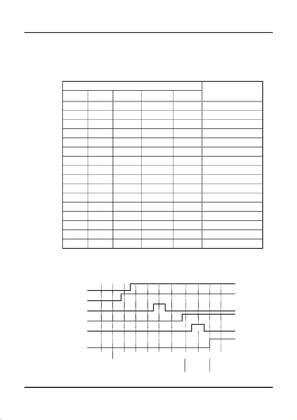
§4. PILOT INPUT of binary method
The PILOT INPUT signals are binary to enable many weld conditions enable to be selected. For the
combination of the PILOT INPUT signals and the schedule no., refer to the following table.
Only when three PILOT INPUT signals are coincided whith each other when checked and confirmed in
synchronization with the power supply the sequence will start.
PILOT INPUT signal Schedule No.
PILOT16
PILOT8
PILOT4 PILOT2 PILOT1
OFF OFF OFF OFF OFF NONE
OFF OFF OFF OFF ON 1
OFF OFF OFF ON ON 3
OFF OFF ON OFF ON 5
OFF OFF ON ON ON 7
OFF
OFF
ON OFF OFF ON 9
OFF ON OFF ON ON 11
OFF
ON
OFF
ON OFF ON 13
OFF ON ON ON ON 15
ON OFF OFF ON OFF 18
ON OFF ON OFF OFF 20
ON OFF ON ON OFF 22
ON ON OFF OFF OFF 24
ON
ON
OFF
OFF ON ON 26
ON ON ON OFF OFF 28
ON
OFF
ON ON ON ON 31
Power cycle
0
1
2 3 4
5 6 7 8 9
10
ON
PILOT INPUT 1
ON
PILOT INPUT 2
PILOT INPUT 4
OFF
PILOT INPUT 8
ON
PILOT INPUT 16
OFF
SEQUENCE
INITIATION
Schedule No.
None
None
3
3
7
3
11
27
11
11
WELCOM 600P
CHOWEL CORPORATION - 17 -
Chapter 2. Programming
Program the operation of the welding Timer unit, the weld condition and the constant of the welder to be
used.
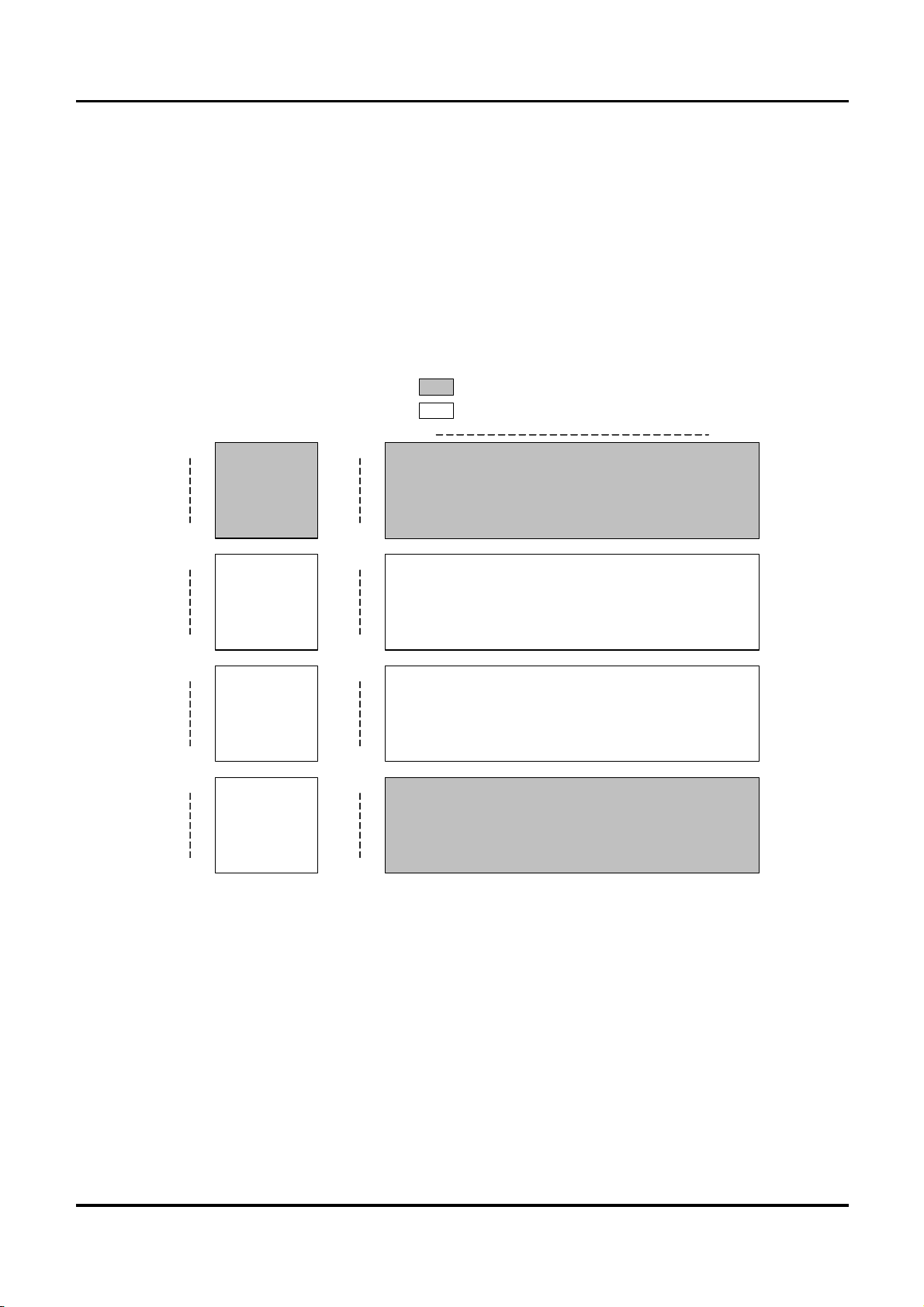
Specify the program schedule common to all schedule with X0, and the SCHEDULE NO. and
VALVE/STEP NO. with X1 through X31.
Both the program data and the monitor data are arranged with X and Y addresses defined as shown in the
following chart.
COMM sch1 sch31
C-00
C-34
D-00
D-06
D-20
D-29
SCHEDULE MONITOR
N-00
N-19
SCHEDULE FAULT RECORD
SCHEDULE PROGRAM
A-00
A-38
Common
Program
area
B-00
B-19
STEPPER
Monitor
Area
B-20
B-29
Common
Monitor
area
M-00
M-29
Common
Error history
area
PROGRAM AREA
MONITOR AREA
STEPPER PROGRAM

WELCOM 600P
CHOWEL CORPORATION - 18 -
§1.Common program
This is a program common to all schedules and specified with X0.
Program the data common to all schedules.
1-1. Control constant program
Program the function and constant common the all the schedule.
A-00 LOW CURRENT LIMIT
Set the weld current drop detect level at 100% for the detection as specified.
A-01 HIGH CURRENT LIMIT
Set the weld current over detect level at 100% for the detection as specified.
A-04 BREAK DETECTION COUNTS
To improve the secondary cable disconnection detect precision, set the internal continuous detect
frequency until the signal is actually put out.
A-05 SHORT DETECTION CURRENT
Set the maximum allowable primary current at the weld gun release time to determine the
secondary cable short-circuit.
A-07 TOTAL WELD COUNT
Set the count up output target value of total weld counter common to all the schedule no.
1-2. Program of fault detect method
Set fault detection method among 0 (NEGLECT), 1 (FAULT), 2 (ALARM) to choose.
When detect fault, they become as follows the action according to the setting up.
a. NEGLECT : it do not a notice output, it is not have an influence on the control action.
b. ALARM : ALARM OUTPUT is turned ON, but not have an influence on the control action.
c. FAULT : FAULT OUTPUT is turned ON, the next pilot is stop.
A-20 LOW CURRENT DETECT
Set the detection action to detect the low current.
A-21 HIGH CURRENT DETECT
Set the detection action to detect the high current.
A-22 LOW VOLTAGE IN WELD
Set the detection action to detect the low voltage in weld.
A-23 SECONDARY CABLE BREAK
Set the detection action to detect th secondary cable break.
A constant current control is valid.

WELCOM 600P
CHOWEL CORPORATION - 19 -
1-3. Operation mode program
Set the operation modes common to all the schedule no. with 0(OFF), 1(ON).
A-30 SPEPPER RESET METHOD
Set the reset method for the step counter and weld counter to control the stepper.
For resetting the complete schedule only, set them at 0, and for resetting all schedule, set them at
1.
A-31 PULSE PILOT
If this is set at 0, the self-holding of the pilot input signal will not be made until the weld
initiations.
Input the pilot signal in pulse, for immediate self-holding, set this at 1.
A-32 FAULT RESET BY PILOT
If this is set at 0, initiation will not be made after the fault is put out until reset is made.
For automatic reset of the FAULT output by the next pilot input, set this at 1.
A-33 WELD COMPLETE AT FAULT
If this is set at 0, the WELD COMPLETE output signal after the abnormal end of the weld
sequence will not be turned on.
Set this at 1, to obtain the WELD COMPLETE output signal even in the case of abnormal
end of the weld sequence.
A-34 REWELD AT FAULT
If this is set at 0, the weld sequence will end in one time whether the weld current fault exists or
not.
Set this at 1, to make automatic reweld in the case where the LOW CURRENT fault,
EXTREMELY LOW CURRENT fault, SCR MISS FIRE due to the foreign substance between a
electrode tips, etc.
A-35 WELD COMPLETE AT FAULT RESET
If this is set at 0, the fault reset mode will resets the fault output only.
Set this at 1 to put out the WELD COMPLETE signal too, at the same time.
A-38 RETRACT PULSE PILOT
The case which the pulse input is used to the retract pulse pilot, this item is set at 1.
(Caution: when the retract ON/OFF switch and FOOT switch is ON, this item is able to use)
If this item is set at 0, the retract input is executed as the ON/OFF signal of the input.
Table of contents
Other CHOWEL Welding Accessories manuals


Popular Welding Accessories manuals by other brands


Argweld
Argweld PurgExtra User instructions

ESAB
ESAB A6 Mastertrac instruction manual

Wire wizard
Wire wizard NSW-20.4F-18B-2 Installation & operation manual

Lincoln Electric
Lincoln Electric K4168-1 Water Cooled 20-250-25R Operator's manual

Lincoln Electric
Lincoln Electric US-M1800-LS datasheet

PROFAX
PROFAX WP-500 operating instructions


