CHOWEL WELCOM-250Y User manual

MM-W250Y,Z-041117(E)
MAINTENANCE MANUAL
FOR
RESISTANCE WELDING CONTROLLER
(MODEL : WELCOM-250Y, WELCOM-250Z)
CHOWEL CORPORATION

WELCOM-250Y, Z MAINTENANCE MANUAL
CHOWEL - 2 -
MAINTENANCE MANUAL
FOR
RESISTANCE WELDING CONTROLLER
Important Safeguards
Read and understand the entire contents of this manual, with special
emphasis on the safety material throughout the manual, before installing, operating,
or maintaining this equipment. This equipment and this manual are for use only by
persons trained and experienced in the safe operation of welding equipment. Do not
allow untrained persons to install, operate or maintain this equipment. Contact your
distributor if you do not fully understand this manual.
WARNING
To guard against injury, the following basic safety precautions should be observed
in the instruction manual of the resistance welding controller
CHOWEL CORPORATION. Model : WELCOM-250Y, WELCOM-250Z
598, SUNGGOK-DONG, DANWON-GU, ANSAN-CITY,
KYUNGGI-DO, REPUBLIC OF KOREA
Copyright CHOWEL CORPORATION
ⓒ
1997
First Printing, March 1997 Printed in Korea

WELCOM-250Y, Z MAINTENANCE MANUAL
CHOWEL - 3 -
CHOWEL has developed this document for its licensees and customers. The information contained
herein is the property of CHOWEL and may not be copied, used, or disclosed to others without prior
written approval from CHOWEL and may not be copied, used, or disclosed to others without prior
written approval from CHOWEL. Users are cautioned that the material contained herein is subject to
change by CHOWEL at any time and without prior notice.
The information contained herein is the property of CHOWEL and shall not be reproduced in whole of in
part without prior written approval of CHOWEL. The information contained herein is subject to change
without notice and should not be constructed as a commitment by CHOWEL.
CHOWEL assumes no responsibility for any errors or omissions in this document.
☞Contact your sales agent for individual warranty coverage.
WHO DO I CONTACT?
CHOWEL CORPORATION
598, SUNGGOK-DONG, ANSAN-CITY,
KYUNGGI-DO, REPUBLIC OF KOREA
ZIP CODE : 425-110
PHONE : 82-31-493-9911 FAX : 82-31-495-2518

WELCOM-250Y, Z MAINTENANCE MANUAL
CHOWEL - 4 -
READ FIRST
To use this welding controller in safety, the operator should follow industry
standards and safety senses whenever working on, or near the weld machine.
In some case, failure to follow the warning instruction can lead to control or
machine damage. In other cases failure to follow these instructions can lead to
injury, or death of personnel.
Some examples of safe practices are listed below. These examples are not to be
considered a comprehensive listing of safety practices.
Always use safety senses when working with any type of machinery.
DANGER
During electrical power is ON, this welding controller is charged with high
voltage electricity. Turn electrical power OFF before open the door.
In the case the door is opened as it is not turn OFF can lead to injury by an
electric shock, or death of personnel.
WARNING
In some case failure to follow these instructions as follows can lead to control
damage or injury of personnel.
1. Ensure that control / machine is connected to the correct voltage before turning
electrical power ON.
2. Whenever power is ON, stand clear of moving parts.
This practice should be used even if the machine is not actually in use.
3. Before turning electrical power OFF, ensure that personnel are standing clear of
moving parts that are pneumatic or hydraulic powered.
4. Whenever electrical power is turned OFF, install a "lock-out" device at the
main disconnect to prevent power from being accidentally turned ON.

WELCOM-250Y, Z MAINTENANCE MANUAL
CHOWEL - 5 -
CAUTION
1. Turn electrical power OFF before changing the tap switch at the weld
transformer.
In the case failure to follow the instruction like a welding at changing the tap
switch can lead to injury to personnel.
2. Turn stop cock OFF before some piping work.
In the case failure to follow the instruction like the electrical circuit is splashed
with cooling water can lead to control damage.
CAUTION
Magnetic fields
It should be borne in mind that welding machine generates intense magnetic fields.
Consequently, “Do not approach the secondary circuit” of the machine carrying on
your person any article that are likely to suffer damage.
These include the following:
-Any kind of magnetic card or badge, for example credit card, bank card,
magnetic strip telephone card, personal recognition cards, magnetic clocking-on
cards, company permits, passes, etc.
-Any kind of magnetic tape or media, for example cassette, video cassette, floppy
disk, etc.
-Any kind of delicate mechanism, for example electronic calculators, cameras,
motion picture cameras, television cameras, watches (especially mechanically
driven ones).
RISK OF ELECTRIC SHOCK
It shows readers where people will be struck by an electric
shock if procedures are not followed properly.

WELCOM-250Y, Z MAINTENANCE MANUAL
CHOWEL - 6 -
CONTENTS
1. Specification of WELCOM-250Y,Z ······································· 7
2. Fault detection ······························································· 11
3. Circuit diagrams ····························································· 15
4. TB30 ·········································································· 31
5. RB10············································································ 34

WELCOM-250Y, Z MAINTENANCE MANUAL
CHOWEL - 7 -
1. Specification of WELCOM-250Y,Z
1-1 Voltage and Frequency
. Welding power supply : Single phase AC440±15%
50/60Hz Automatic selection
. Control power supply : Unnecessary due to be fed from a
voltage dropped welding power supply.
. Power consumption : 50VA (No working condition)
1-2 Environments
. Temperature : -5℃∼+ 50℃( 23℉∼122℉)
. Humidity : 90% or less without dewing
1-3 Cooling Condition
. Controller : Natural air cooled
. SCR : Water cooled
Temperature at water inlet : 30℃or less
(86℉or less)
Quantity of water : More then 5 liters per minute
(More then 1.321 gallons per minute)
Cooling water pressure : Max. 3Kgf/㎠
Resistively : More then 5000 ohms/centimeter
(More then 1969 ohms .inch)
1-4 Control Element : SCR size D
(900A / 1200V 100% duty cycle)
1-5 Current Control System : Synchronous phase control by SCR.
1-6 Weld current control method
. Constant current control : Loop control by primary current feedback
. Voltage compensation control : Open-loop control by measuring
welding power supply.
1-7 Control Range
. Firing angle control range : 20 - 135 degrees
. Pri, current control range : 50 - 1500amps (limit by SCR size)
. 2nd current control range : 2.0 KA - 25.5 KA
. Turn ration of transformer : 1.0 - 199.9

WELCOM-250Y, Z MAINTENANCE MANUAL
CHOWEL - 8 -
. Time range Initial squeeze time : 0 - 99 CYC
Squeeze time : 1 - 99 CYC
Up-slope time : 0 - 30 CYC
#1 weld time : 0 - 99 CYC
Down slope time : 0 - 30 CYC
#2 weld time : 0 - 99 CYC
Hold time : 1 - 99 CYC
Weld complete delay time : 0 - 99 CYC
Off time : 1 - 99 CYC
1-8 Input signals
. Pilot : 4 (14 schedule, binary 4 bit)
. Weld/No weld : 1
. Count reset : 1
. Stepper reset : 1
. Fault reset : 1
. External thermo : 1
. Input open circuit voltage 24V DC
. Input short circuit current 12mA
1-9 Output signals
. Gun valve : 2
Gun valve output capacity 24V DC, 0.5A
. Weld complete : 1a
. Count up : 1a
. Stepper complete : 1a
. Fault : 1a
. Alarm : 1a
. Contact load voltage AC130Vrms, DC170V(Cont.max.value)
. Contact load current 0.15A (Cont. max. value)
1-10 Stepper
. Stepper schedule : 14
. Number of step : 10 (Including #0 of first step)
. No. of weld count per step : 0 to 9999 (#0 : 1 to 9999)
. Current ratio : based on step #0 * 50% to 200%
. Stepper reset : Select completed stepper or all
stepper

WELCOM-250Y, Z MAINTENANCE MANUAL
CHOWEL - 9 -
1-11 Counter
. Total weld counter : 1 / 1 to 99,999,999
. Each schedule counter : 14 / 1 to 99,999,999
1-12 Fault detection
. Controller failure : Fault output
. Internal power failure : Fault output
. Internal parts failure : Fault output
. Low line voltage : Alarm output
. Illegal power frequency : Fault output
. Low voltage in weld : Fault output
. Memory data error : Fault output
. Current program error : Fault output
. No current : Fault output
. SCR short : Fault output
. 2nd cable break : Alarm output
. 2nd cable short : Fault output
. SCR over temperature : Fault output
. Extremely low current : Fault output
(Less then 50%)
. Low current : Fault output
. High current : Fault output
. Communication error : Fault output
. Undefined error : Fault output
1-13 Monitor
. Monitor according to each schedule
C.T input gain : 1 to 16 (2,880 to 180amp FS)
Weld power factor : 0 to 90 degree
Weld T/R margin : 0 to 99 %
Test current : 0 to 25,500 amp
Average test current : 0 to 25,500 amp
Times judged cable breaking : 0 to 9 times
Each schedule weld count value : 0 to 99,999,999
. Common monitor
#1 weld time : 0 to 99 CYC
#2 weld time : 0 to 99 CYC
Index no. : 0 to 255

WELCOM-250Y, Z MAINTENANCE MANUAL
CHOWEL - 10 -
Schedule no. : 1 to 14
Fault code : 0 to 99
Total weld count value : 0 to 99,999,999
Target control current, #1,#2 weld : 2.0KA to 25.5KA
Average Firing angle, #1,#2 weld : 20 to 150 degree
Average extinction angle, #1,#2 weld : 0 to 90 degree
Average conducting angle, #1,#2 weld: 0 to 180 degree
Average weld current, #1,#2 weld : 2.0KA to 25.5KA
Average power supply, #1,#2 weld : 75% to 125%
1-14 Fault recording function
. Fault code number : The lasts 10 per each schedule.
. Weld schedule number : The lasts 10 of fault schedule number.
1-15 Memory data maintenance
. Battery : Lithium battery
. Life time : More than 5 years

WELCOM-250Y, Z MAINTENANCE MANUAL
CHOWEL - 11 -
2. Fault detection
Fault is checked for at the time of power on, inactive status, start and
sequence end and alarm the detection according to its cause.
2-1 Fault detection items
The followings are the typical times, details and remedies of fault
for each fault code. Use them for troubleshooting.
. E01 CONTROLLER FAILURE
This fault is checked for when the power is turned on.
If the fault is fatal due to the detect of the memory I.C, output
to or communication with the external will be impossible.
If the controller failure indicator will be turned ON and the
communication to the external is impossible, replace the timer unit.
. E02 INITIAL POWER FAILURE
This fault is checked for when the power is turned on, and alarmed
immediately, if any.
This fault indicates that there is a trouble with the control power built
in the welding controller.
Replace the welding controller.
This fault can not be reset. To make sure of normal operation of
the new controller, turn ON the power again.
. E03 INTERNAL PARTS FAILURE
This fault is checked for when the power is turned on, and alarmed
immediately, if any.
This fault indicates that there is a trouble with some parts in the timer unit.
Replace the timer unit.
This fault can not be reset. To make sure of normal operation of
the new controller, turn ON the power again.
. E10 LOW LINE VOLTAGE
This fault is checked for when the power is turned on, and alarmed
immediately, if any.
This fault indicates that the weld line voltage dropped below the
lower limit for at least several second.
Check whether the weld line voltage matches up to the rated voltage or not.

WELCOM-250Y, Z MAINTENANCE MANUAL
CHOWEL - 12 -
. E11 ILLEGAL POWER FREQUENCY
This fault is checked for when the power is turned on, and alarmed
immediately, if any.
This fault indicates that the weld line frequency could not be
identified when the power is turn on.
Check whether the power supply is unstable or not.
Reset this fault by turning ON the power again.
. E12 LOW VOLTAGE IN WELD
This fault is checked for when the power is turned on, and alarmed
immediately, if any.
This fault indicates that the power has been shut OFF during the
welding or the drastic voltage drop was caused. Check whether
the weld during the power shut-off is defective or not.
. E20 MEMORY DATA ERROR
This error is checked for when the power is turned ON, and
initiation, and alarmed immediately, if any.
This error indicates that the data in the memory was destroyed
or is outside of the specified range.
Reset the whole area of the program and monitor whether it has
been used or not.
. E21 CURRENT PROGRAM ERROR
This error is checked for during the weld current control, and
alarmed when sequence ends.
This error indicates that the current set value excesses the controllable range
during the constant current control calculation processing.
Check whether the current and the weld transformer turns ratio
have been properly set or not.
. E30 NO CURRENT FAULT
This fault is checked for during the weld current control, and
alarmed when the sequence ends.
This fault indicates that the weld current was excessively low due to dirt
caught by the electrode tips or the thyristor failed in firing control.
Check whether there is dirt caught by the electrode tips or the initial
squeeze time is sufficient or not.

WELCOM-250Y, Z MAINTENANCE MANUAL
CHOWEL - 13 -
. E31 SCR SHORT
This fault is checked for always while welding is not active, and
alarmed immediately, if any.
This fault indicates that the thyristor came to be short circuited.
Replaced the thyristor and check whether the weld current is
above the rated current or not.
. E40 SECONDARY CABLE BREAK
This fault is checked for when the welding ends, and alarmed at the end of the sequence.
This fault indicates that the disconnection of the secondary cable is imminent.
The imminent disconnection is predicted based on the probability.
Before replacing the secondary cable.
Check the impedance again for the reconfirmation purpose.
. E41 SECONDARY CABLE BREAK
This fault is checked for when the secondary cable short circuit test is made,
and alarmed immediately, if any.
This fault indicates that the secondary cable is short circuited or almost short circuited.
Replace the secondary cable.
. E50 SCR OVER TEMPERATURE
This fault is checked for at the initiation, and alarmed
immediately, if any.
This fault indicates that the thyristor or the weld transformer is over temperature.
Check the duty factor and the temperature and flow of the coolant.
. E60 EXTREMELY LOW CURRENT
This fault is checked for during the weld current control ends,
and alarmed when the sequence ends.
This fault indicates that the weld current was excessively small.
Check the weld cable for disconnection the weld and the electrode for dirt.
. E61 LOW CURRENT
This fault is checked for during the weld current control ends,
and alarmed when the sequence ends.
This fault indicates that the weld current was below the low current limit level.
Check the weld cable for disconnection the weld and the electrode for dirt.

WELCOM-250Y, Z MAINTENANCE MANUAL
CHOWEL - 14 -
. E62 HIGH CURRENT
This fault is checked for when the weld current control ends,
and alarmed when the sequence ends.
This fault indicates that the weld current is above the high current limit level.
Check whether the weld current and the over current detect set
level have been set properly or not.
. E98 COMMUNICATION ERROR
This fault is always checked for, but the indication is made only in DSTB or DSRB and
the timer unit does not alarm this fault because it continues the control operation.
This fault indicates that there is a trouble with communication.
Check the communication connector and the communication cable for disconnecting.
. E99 UNDEFINED ERROR
This indicates the reserve code in which the fault codes are not classified or defined.
Record the operation status when this fault occurred and replace the welding controller.
2-2 If any of the followings is the case, the fuse may be blown.
a. When the power is turned ON, there is no I/O indication.
Check the primary protection fuse (F1) in the contactor for blowing.
b. When any schedule is activated, the valve indicator is turned on,
but the weld gun does not press at all.
Check the press circuit protection fuse (F1) in the printed
circuit board of the timer for blowing.
c. When the power is turned ON, neither T/B nor R/B indicates at all.
Check the T/B and R/B power protection fuse (F2) in the PCB
of the timer for blowing.
WELCOM-250Y, Z MAINTENANCE MANUAL
CHOWEL - 15 -
3. Circuit diagrams
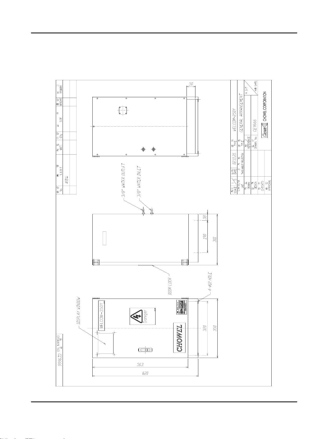
3-1 Layout diagram for WELCOM-250Y

WELCOM-250Y, Z MAINTENANCE MANUAL
CHOWEL - 16 -
3-2 Layout diagram for WELCOM-250Z

WELCOM-250Y, Z MAINTENANCE MANUAL
CHOWEL - 17 -
3-3 Timer unit and I/O display
WELCOM-250Y, Z MAINTENANCE MANUAL
CHOWEL - 18 -
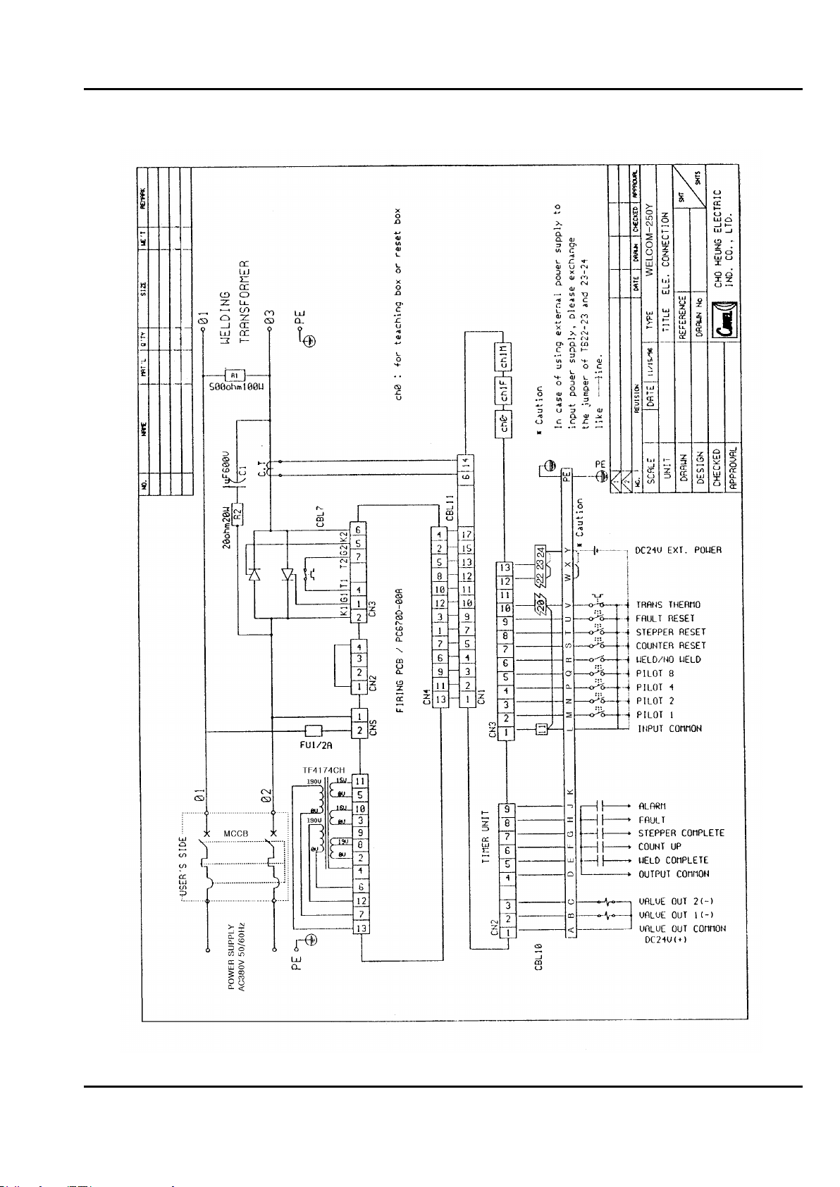
3-4 Electrical connection for WELCOM-250Y

WELCOM-250Y, Z MAINTENANCE MANUAL
CHOWEL - 19 -
3-5 Electrical connection for WELCOM-250Z
WELCOM-250Y, Z MAINTENANCE MANUAL
CHOWEL - 20 -
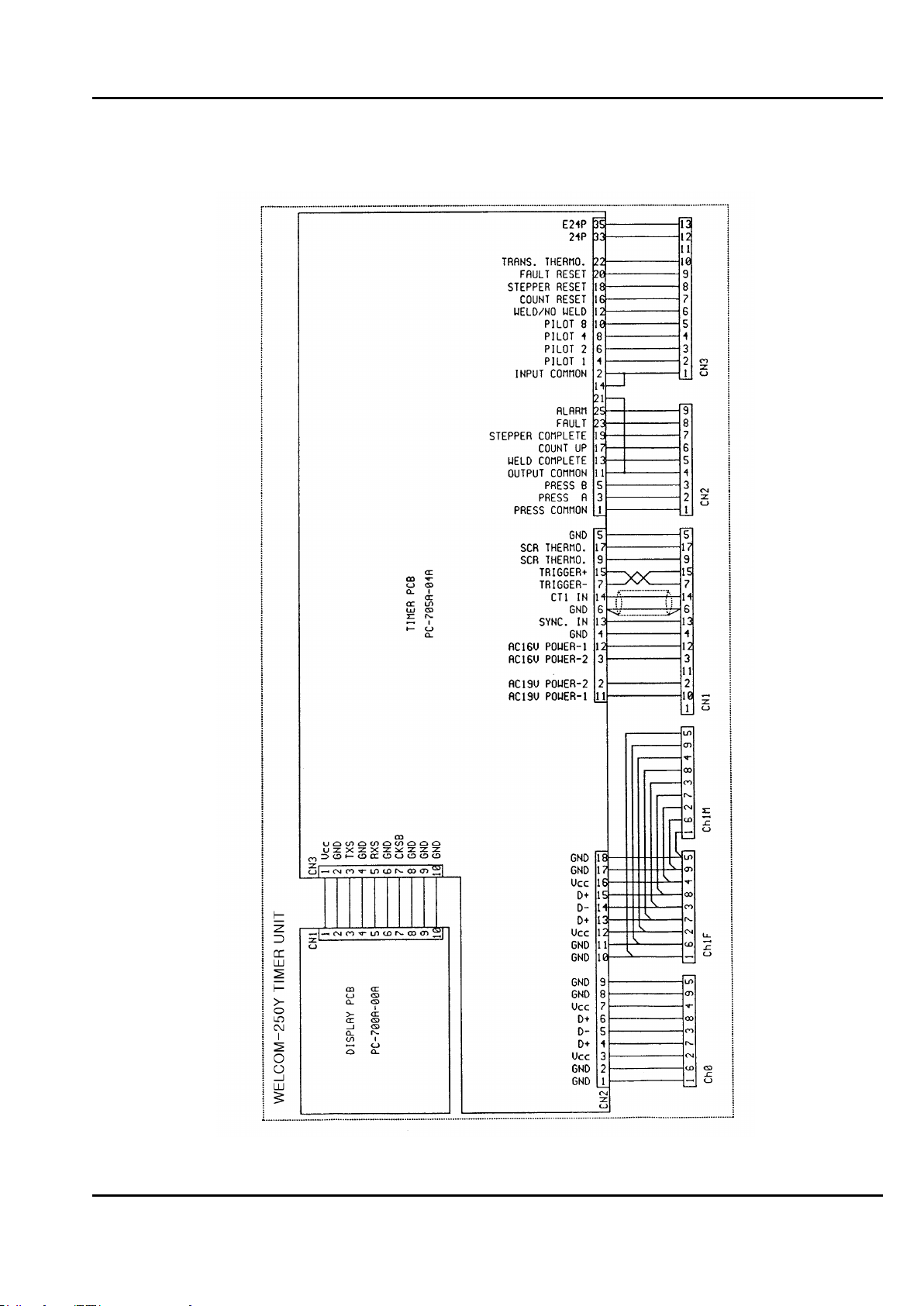
3-6 Connection diagram for WELCOM-250Y timer unit
This manual suits for next models
1
Table of contents
Other CHOWEL Welding Accessories manuals


