Weco Discovery 220T Evo User manual

Cod. 006.0001.2020
16/11/2021 V.2.1
Discovery 220T Evo/VRD Evo
Discovery 300T Evo/VRD Evo
Instruction manual
ENG
Translation of original instructions

Cod. 006.0001.2020
16/11/2021 V.2.1 Discovery 220T Evo/VRD Evo
Discovery 300T Evo/VRD Evo
2

Cod. 006.0001.2020
16/11/2021 V.2.1
Discovery 220T Evo/VRD Evo
Discovery 300T Evo/VRD Evo
3

Cod. 006.0001.2020
16/11/2021 V.2.1 Discovery 220T Evo/VRD Evo
Discovery 300T Evo/VRD Evo
4
1 INTRODUCTION
IMPORTANT!
This handbook must be consigned to the user prior to installation and commissioning of the unit.
Read the "General prescriptions for use" handbook supplied separately from this handbook before
installing and commissioning the unit.
The meaning of the symbols in this manual and the associated precautionary information are given in
the "General prescriptions for use”.
If the "General prescriptions for use" are not present, it is mandatory to request a replacement copy
from the manufacturer or from your dealer.
Retain these documents for future consultation.
LEGEND
DANGER!
This pictogram warns of danger of death or serious injury.
WARNING!
This pictogram warns of a risk of injury or damage to property.
CAUTION!
This pictogram warns of a potentially hazardous situation.
INFORMATION
This pictogram gives important information concerning the execution of the relevant operations.
Thissymbolidentiesanactionthatoccursautomaticallyasaresultofapreviousaction.
Thissymbolidentiesadditionalinformationorareferencetoadifferentsectionofthemanual
containing the associated information.
§ Thissymbolidentiesareferencetoachapterofthemanual.
*1 The symbol refers to the associated numbered note.
NOTES
Theguresinthismanualarepurelyguidelineandtheimagesmaycontaindifferenceswithrespectto
theactualequipmenttowhichtheyrefer.

Cod. 006.0001.2020
16/11/2021 V.2.1
Discovery 220T Evo/VRD Evo
Discovery 300T Evo/VRD Evo
5
1.1 INTRODUCTION
Discovery220T/300TEvo/VRDEvoisaninverter-basedweldingpowersourcecompletewithallthe
functionsrequiredforDCTIGandMMAweldingwithexcellentarccharacteristics.
Thesolidityofthecomponentsofthisunitmakesitareliableworkingcompanionforworkshopand
outdoor applications.
This unit is ideal for maintenance, food industry, hydraulics, oil pipelines and chemical plants.
TheparameterspresetintheDCTIGpulsedsynergiccurvesimplifyweldingbyregulationexclusively
of the current.
ThecurrentisadjustablealsofromtheUp-Downtorch.
Thesimplyandintuitiveinterfaceallowshighprecisionadjustmentswith50storableprograms.
Thewiderangeofadjustablepulsed frequencyincombination withthecomplementary parameters
(basecurrentanddutycycle)makesitpossibletoweldinslowandfastpulsedmode.
Accessories/ancillary devices that can be connected to the unit:
- manualremotecontrolforremoteadjustmentoftheweldingcurrent.
- foot-pedalremotecontrolforTIGtorcharcstrikingandremoteadjustmentofweldingcurrent.
- UP/DOWNtorchortorchwithpotentiometer.
- liquid cooler for TIG torches.
Consultyourdealerforanupdatedlistofaccessoriesandthelatestnewproductsavailable.

Cod. 006.0001.2020
16/11/2021 V.2.1 Discovery 220T Evo/VRD Evo
Discovery 300T Evo/VRD Evo
6
2 INSTALLATION
DANGER!
Lifting and positioning
Read the warnings highlighted by the following symbols in the “General prescriptions for use”.
2.1 CONNECTIONS TO THE ELECTRICAL MAINS NETWORK
Themainspowersupplyfeaturestowhichtheequipmentshouldbeconnectedaregiveninchapter“12
TECHNICAL DATA” at page 57.
The machine can be connected to motorgenerators provided their voltage is stabilised.
Connect/disconnectthevariousdeviceswiththemachineswitchedoff.
2.2 FRONT PANEL
1234
○ Negativepoleweldingsocket.[Item1].
○ Connectorforgasfeedhose:gasowfromthepowersourcetothetorch.[Item2].
○ TIGTORCHcontrolconnector[Item3].
○ Positivepoleweldingsocket.[Item4].

Cod. 006.0001.2020
16/11/2021 V.2.1
Discovery 220T Evo/VRD Evo
Discovery 300T Evo/VRD Evo
7
2.3 REAR PANEL
1 2 4
5
○ Remotecontrolconnector[Item1].
○ Connectorforgasfeedhose:gasowfromthecylindertothepowersource[Item2].
○ Coolingunitpowerfeedingconnector[Item3].
• Voltage: 230 V a.c.
• Current output: 1.35 A
• IP protection rating: IP20 (cap open) / IP66 (cap closed)
DANGER!
High voltage!
If the socket is not connected to any devices always close the cap
○ WeldingpowersourceON/OFFswitch[Item4].
○ Powercable.[Item5].
• Length (outer side): 2,05 m
• Numberandcrosssectionofwires:3x2.5mm2(on 220T Evo/VRD Evo)/4x2.5mm2(on
300T Evo/VRD Evo)
• Powerplugtype:Schuko250Va.c./16A(on220T Evo/VRD Evo) / not supplied (on 300T
Evo/VRD Evo)

Cod. 006.0001.2020
16/11/2021 V.2.1 Discovery 220T Evo/VRD Evo
Discovery 300T Evo/VRD Evo
8
2.4 PREPARING FOR MMA WELDING
1. SettheweldingpowersourceON/OFFswitchto“O”(unitswitchedoff).
2. Plugthepowercableplugintoamainssocketoutlet.
3. Choosetheelectrodebasedonthetypeofmaterialandthicknessoftheworkpiecetobewelded.
4. Insert the electrode in the electrode holder.
5. Connecttheelectrodeholdercabletotheweldingsocketbasedonthepolarityrequestedbythe
type of electrode used.
6. Connecttheplugofthegroundclamptotheweldingsocketonthebasisofthepolarityrequired.
7. Connecttheearthclamptotheworkpiecebeingprocessed.
DANGER!
Electric shock hazard!
Read the warnings highlighted by the following symbols in the “General prescriptions for use”.
8. SettheweldingpowersourceON/OFFswitchto“I”(unitpowered).
9. Selectthefollowingweldingmodeontheuserinterface:MMA
10.Settherequiredweldingparametervaluesontheuserinterface.
Whentheremotecontroller[RC]isconnectedandtherelativelockingscrewistightened,welding
current can be adjusted using the remote controller.
Thesystemisreadytostartwelding.
REAR VIEW FRONT VIEW
(polarity to basic electrode)
REMOTE
CONTROL

Cod. 006.0001.2020
16/11/2021 V.2.1
Discovery 220T Evo/VRD Evo
Discovery 300T Evo/VRD Evo
9
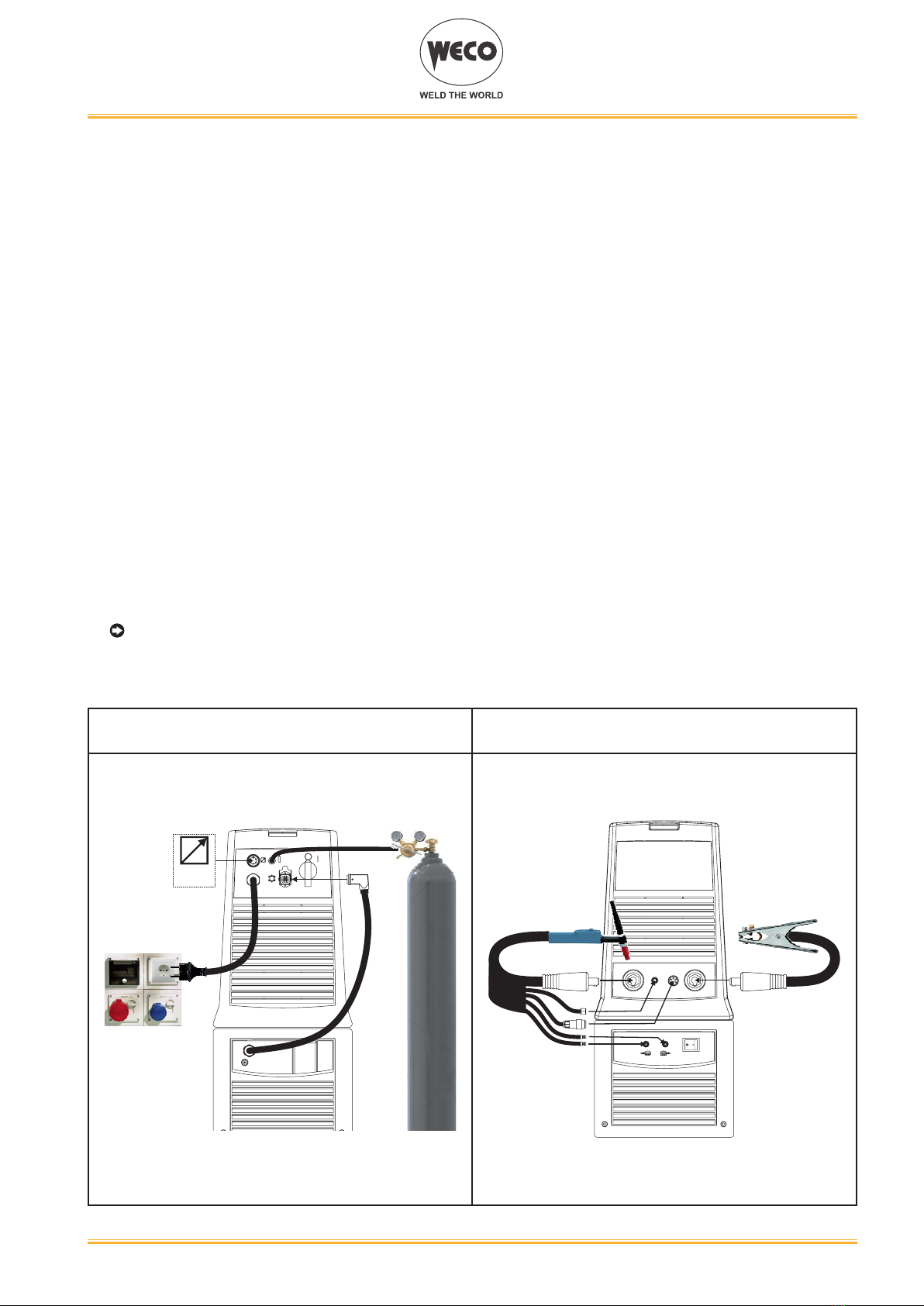
2.5 PREPARING FOR TIG WELDING
NOTE: For the cooler to power source assembly procedure refer to the cooler instruction
manual.
1. SettheweldingpowersourceON/OFFswitchto“O”(unitde-energized).
2. Plugthepowercableplugintoamainssocketoutlet.
3. Connectthegashosefromtheweldinggascylindertothereargassocket.
4. Open the cylinder gas valve.
5. Choosetheelectrodebasedonthetypeofmaterialandthicknessoftheworkpiecetobewelded.
6. Insert the electrode in the TIG torch.
7. Connectthetorchplugtotheweldingsocketonthebasisofthepolarityrequiredbythetypeof
electrode in question.
8. Connecttheplugofthegroundclamptotheweldingsocketonthebasisofthepolarityrequired.
9. Connectthegashosefromtheweldingtorchtothefrontgassocket.
10.ConnecttheweldingtorchconnectortotheTIGtorchsignalsconnector.
11.Connecttheearthclamptotheworkpiecebeingprocessed.
12.SettheweldingpowersourceON/OFFswitchto“I”(unitpowered).
13.Selectthefollowingweldingmodeontheuserinterface:DCTIG
14.Pressthetorchtriggerwiththetorchwellclearofanymetalparts.Thisservestoopenthegas
solenoidvalvewithoutstrikingtheweldingarc.
15.Usetheowcontrolvalvetoadjusttheowofgasasrequiredwhilethegasisowingout.
16.Settherequiredweldingparametervaluesontheuserinterface.
Whentheremotecontrolpedalisconnectedandtherelativelockingscrewistightenedtheweld-
ingcurrentwillvaryinrelationtothepressureexertedonthepedal.
Thesystemisreadytostartwelding.
REAR VIEW FRONT VIEW
(polarity for tungsten electrode)
REMOTE
CONTROL

Cod. 006.0001.2020
16/11/2021 V.2.1 Discovery 220T Evo/VRD Evo
Discovery 300T Evo/VRD Evo
10
3 USER INTERFACE
Discovery 220T Evo/VRD Evo - Discovery 300T Evo/VRD Evo
DYN arc
QST
M-TACK
MenuMenu
Q-SPOT
HF E1/S5
S3
L1
D1
USB S4S2S1
L2
L3
L4
L5
L6
L7
L8
L9
L10
L11
L12
SYNSYN
L13
CODE SYMBOL DESCRIPTION
L1
QST
DCTIGmode:illuminationshowsthatthefollowingparametercanbeset:Q-START
L2
DYN arc
DCTIGmode:illuminationshowsthatthefollowingparametercanbeset:DYNAMICARC
L3
M-TACK
DCTIGmode:illuminationshowsthatthefollowingparametercanbeset:MULTITACK
L4 DCTIGmode:illuminationshowsthatthefollowingparametercanbeset:ELECTRODEDIA-
METER (mm)
L5
HF
Illumination shows that the following function has been activated: HIGH FREQUENCYARC
STRIKE (HF)
L6 Illuminationshowsthatthefollowingfunctionhasbeenactivated:2strokeprocedure.
L7 Illuminationshowsthatthefollowingfunctionhasbeenactivated:4strokeprocedure.
L8 Illuminationshowsthatthefollowingfunctionhasbeenactivated:4strokeB-levelprocedure
L9
Q-SPOT
Illuminationshowsthatthefollowingfunctionhasbeenactivated:2strokespotprocedure(Q-
SPOT).
L10 ThisLEDilluminatestoshowthatthefollowingweldingmodeisselected:MMA
L11 ThisLEDilluminatestoshowthatthefollowingweldingmodeisselected:CONTINUOUSDC
TIG
L12 ThisLEDilluminatestoshowthatthefollowingweldingmodeisselected:PULSEDDCTIG
L13
SYN
ThisLEDilluminatestoshowthatthefollowingweldingmodeisselected:SYNERGICPULSED
DC TIG
When this is on, it means that the synergic mode is active and that the operator can set just the
weldingcurrent whilethe otherparametersareautomaticallyregulatedbythemachine.The
synergyisoptimisedforanglewelding.

Cod. 006.0001.2020
16/11/2021 V.2.1
Discovery 220T Evo/VRD Evo
Discovery 300T Evo/VRD Evo
11
CODE SYMBOL DESCRIPTION
S1 DC TIG mode: Press the button to select the DC TIG special functions.
Possible choices: Q-START - DYNAMIC ARC - MULTI TACK - ELECTRODE DIAMETER
S2 Press the button to access the JOB MENU.
S3 DC TIG mode: This button selects the torch trigger procedure.
S4 Thisbuttonselectstheweldingmode.
E1/S5
MenuMenu
-Keepthebuttonpressedwhilepoweringonthepowersource:thebuttonopenstheSET-UP
menu.
-Pressandrelease:thebuttonselectstherstlevelmenuparameters.
-Holddownfor3seconds:thebuttonopensthesecondlevelmenu.Wheninthemenu,press
and release the button to select the parameters.
-Data setting: The encoder sets the value of the selected parameter.
-Duringtheweldingoperations:Theencodersetsthevalueofthefollowingparameter:WEL-
DING CURRENT
USB PortprovidedtoconnectaUSBmemorysticktoexport/importJOBs.
D1
IDatasetting:Thedisplayshowstheparametertobeset,itsvalueandthegraphicsymbolas-
sociated to it.
Welding:Thedisplayshowstheeffectiveamperesvalueduringwelding.
4 UNIT POWER-UP
SettheweldingpowersourceON/OFFswitchto“I”toswitchontheunit.
Themessageappearsonthefollowingdisplay:D1.
FX.X=softwareversion
300T
EVO
F.X.X
300T-VRD
EVO
F.X.X
Firstpower-uporpower-upsfollowingaRESETprocedure
Theweldingpowersourcesetsupforweldingwiththefactorypre-sets.
Subsequentpower-ups
Theweldingpowersourcesetsupforweldinginthelateststableweldingcongurationthatwasactive
atthetimeofpower-off.

Cod. 006.0001.2020
16/11/2021 V.2.1 Discovery 220T Evo/VRD Evo
Discovery 300T Evo/VRD Evo
12
5 RESET (LOAD FACTORY SETTINGS)
DYN arc
QST
M-TACK
MenuMenu
Q-SPOT
HF E1/S5
S3
L1
D1
USB S4S2S1
L2
L3
L4
L5
L6
L7
L8
L9
L10
L11
L12
SYNSYN
L13
SET-UP (14/15)
-----------------------------------------------------
MAX CORR.UP OFF
COUNTERS *****
RESET PAR
C
B
A
OUTPUT
ACTIVATION
SELECTION
The reset procedure involves complete restoration of the default values, parameters and memory set-
tings set in the factory.
Theresetprocedureisusefulinthefollowingcases:
- Toomanychangesmadetotheweldingparameterssouserndsitdifculttorestoredefaults.
- Unidentiedsoftwareproblemsthatpreventtheweldingpowersourcefromfunctioningcorrectly.
PARTIAL RESET
Theresetprocedureinvolvesrestorationoftheparametervaluesandsettings,exceptthefollowing
settings:
- Settings of the SETUP menu.
- Saved JOBS.
TOTAL RESET
The reset procedure involves complete restoration of the default values, parameters and memory set-
tings set in the factory.
Allmemorylocationswillberesetandhenceallyourpersonalweldingsettingswillbelost!
A
○ SettheweldingpowersourceON/OFFswitchto“O”toswitchtheunitoff.
○Holding the S5 button
MenuMenu
down,turnthepowersourceswitchto“I”tostarttheunit[
SIMULTANEOUS ACTIONS ].
○Display D1showstheSET-UP MENU.

Cod. 006.0001.2020
16/11/2021 V.2.1
Discovery 220T Evo/VRD Evo
Discovery 300T Evo/VRD Evo
13
B
○ Selectwithencoder E1
MenuMenu
thefollowingsetting: RESET.
○Press the S5 button
MenuMenu
.
○ Selectwithencoder E1
MenuMenu
thefollowingsetting: PAR (partial) o TOT (total).
○Press the S5 button
MenuMenu
.Amessagerequestingtoconrmisdisplayed.
C
○Exit with conrmation
- Press the S5 button
MenuMenu
.
- Wait for the memory clear procedure to terminate.
- Press the S1 button toexittheSET-UPmenu.
○Exit without conrmation
- Press the S1 button .
- Press the S1 button toexittheSET-UPmenu.

Cod. 006.0001.2020
16/11/2021 V.2.1 Discovery 220T Evo/VRD Evo
Discovery 300T Evo/VRD Evo
14
6 SET UP (INITIAL SET-UP OF THE WELDING POWER SOURCE)
DYN arc
QST
M-TACK
MenuMenu
Q-SPOT
HF E1/S5
S3
L1
D1
USB S4S2S1
L2
L3
L4
L5
L6
L7
L8
L9
L10
L11
L12
SYNSYN
L13
A
C
B
SET-UP (1/15)
-----------------------------------------------------
LANGUAGE ENG
COOLING TYPE AUT
STARTING CURRENT %
ACTIVATION
OUTPUT
A
○ SettheweldingpowersourceON/OFFswitchto“O”toswitchtheunitoff.
○Holding the S5 button
MenuMenu
down,turnthepowersourceswitchto“I”tostarttheunit[
SIMULTANEOUS ACTIONS ].
○ DisplayD1showstheMENU SET-UP.
B
○ Selectwithencoder E1
MenuMenu
the setting to be edited.
○Press the S5 button
MenuMenu
toconrm.
○Using the E1
MenuMenu
, edit the value of the selected setting. The value is saved automatically.
○Press the S5 button
MenuMenu
. It returns to the list of settings..
C
○Exit with conrmation
- Press the S1 button .
SELECTION

Cod. 006.0001.2020
16/11/2021 V.2.1
Discovery 220T Evo/VRD Evo
Discovery 300T Evo/VRD Evo
15
Tab. 1 - Impostazioni di Setup
IMPOSTAZIONE MIN DEFAULT MAX NOTE
LANGUAGE EN ENGLISH
ITALIANO
FRANÇAIS
DEUTSCH
ESPAÑOL
PORTUGUES
DUTCH
CESKY
SRBSKI
POLSKI
SUOMI
COOLING TYPE ON AUT OFF
STARTING CURRENT % % A
FINAL CURRENT % % A
HF CURRENT 20 A SYN 200 A
HF TIME 0.5 s 2.0 s 3.0 s
PULSED TYPE SLOW FAST FAST
PILOT ARC OFF ON ON
ENABLE READ I. OFF ON ON
TORCH TYPE 1 1 2
PEDAL TYPE 2 2 9
MAX CURR. UP
COUNTERS
RESET PAR TOT TOT
SERVICE VAL VAL CAL
ER ACTIVATION GROUP
○ ON=Thecoolerisalwaysrunningwhenthepowersourceisswitchedon.Thismodeispreferable
forheavydutyandautomaticweldingprocedures.
○ OFF=Thecoolerisalwaysdisabledbecauseanair-cooledtorchisinuse.
○ AUT=Whentheunitisswitchedonthecoolerisswitchedonfor15s.Duringweldingprocedures
thecoolerrunsconstantly.Whenweldingisterminatedthecoolercontinuestorunfor90s+a
numberofsecondsequivalenttotheaveragecurrentvalueshownusingtheHOLDfunction.
Torch loading
WARNING!
Make sure the torch in use is correctly sized in relation to the welding current required and for
the available and selected cooling type. This prevents the risk of burns to which the operator is
potentially exposed, potential faults, and irreversible damage to the torch and the system.
If a torch is installed or replaced while the unit is running, the circuit of the newly installed torch
must be lled with coolant to avoid the risk of damage to the torch in the case of high voltage arc
strikes without any liquid in the circuit.

Cod. 006.0001.2020
16/11/2021 V.2.1 Discovery 220T Evo/VRD Evo
Discovery 300T Evo/VRD Evo
16
Power-up with operation of the cooler set to “ON” or “AUT” mode
○A check is performed automatically of the presence of liquid in the cooling circuit and the cooler
isswitchedonfor15seconds.
○ Ifthecoolantcircuitisfull,thepowersourcesetsupinthemostrecentstableweldingcongura-
tion.
○ Ifthecoolantcircuitisnotfull,allfunctionsareinhibitedandtherewillbenooutputpowerpresent.
UNIT ALARM!:Themessagewillappearondisplay D1
Press the (generic) button to repeat the checking procedure for an additional 15 seconds.
If the problem persists, rectify the cause of the alarm.
Power-up with operation of the cooler set to “OFF”
Operation of the cooler and the cooler alarm are disabled.
Weldingisperformedwithoutliquidcoolingofthetorch.
Torch change-over with operation of the cooler set to “ON”
Press and release the torch trigger.
Thisservestostartthecoolerfor15secondstollthetorchcoolingcircuit.
- STARTING CURRENT
○ Thevalueofthisparametercanbesetasapercentageoftheweldingcurrentorasanabsolute
valueexpressedinAmperes.
- FINAL CURRENT
○ Thevalueofthisparametercanbesetasapercentageoftheweldingcurrentorasanabsolute
valueexpressedinAmperes.
- HF CURRENT
○This parameter establishes the current value during HF discharge. The value of this parameter
can be set as an absolute value or in SYN.
○ WithSYNsettingtheHFcurrentvalueiscalculatedautomaticallyonthebasisofthepre-setweld-
ing current value.
Consequences of a higher value:
• Arcstrikingisfacilitated,evenonverydirtyworkpieces.
• Riskofpiercingexcessivelythingaugeworkpieces.
- HF TIME
○ Thisparameterdenesthemaximumhighfrequency(HF)arcstrikeduration.
- PULSED TYPE
○SLOW =Thissettingenablesslowpulsedmode.Thepeaktimeandbasetimeareset.
○FAST= This setting enables fast pulsed mode. The frequency and duty-cycle are set.
- PILOT ARC
○ Thefunctionenablestheoutputofalowcurrentbetweenthe1stand2ndtimesofthetorchtrig-
gertoshieldthemaskinadvanceandavoidtheriskofblindingashbackcausedbythewelding
current.
- ENABLE READ CURRENT
○ Thisfunctionallowsfortherealweldingcurrentdisplaytobeenabledordisabled.

Cod. 006.0001.2020
16/11/2021 V.2.1
Discovery 220T Evo/VRD Evo
Discovery 300T Evo/VRD Evo
17
- TORCH TYPE
The parameter changes the torch trigger operating mode.
• oFF: indicates standard operation.
• 1:speciesthe4TB-levelmanagementvariant.Allowsthetransitiontothesecondarywelding
currentbypressingandholdingdowntheUPorDOWNbutton;whenthebuttonisreleased,
the primary current is restored. With variant oFF selected, the UP/DOWN buttons are disabled
for all procedures.
• 2:speciesthedownslopemanagementvariant.Byreleasingthetorchtriggerduringthethird
stroke(3S)thedownslopeisstoppedandthenalcurrentisimmediatelydeliveredwithout
havingtogothroughtheentireslopetime.TheHFrestartduringthedownslopeisdisabled.
- PEDAL TYPE
○The parameter selects the type of pedal used:
• RC02 standard pedal type
• RC09 special pedal type. This type of pedal recognises the pressure applied to the foot pedal
orthetorchbutton,switchingautomaticallyfrominternaladjustmenttoexternalcontrolusing
the pedal.
- MAX CURR. UP
WhentheparameterissettoON,themaximumvalueoftheweldingcurrentthatcanbesetwiththeUP
/DOWNtorchisthecurrentsetbytheencoderinthefrontpaneloftheweldingpowersource.Whenthe
parameterissettoOFF,themaximumvalueoftheweldingcurrentthatcanbesetwiththeUP/DOWN
torchisthemaximumcurrentthatcanbesuppliedbytheweldingpowersource.
- OPERATING HOUR COUNTER
○ Themenupageshowstheprocessinghourcounters.
• POWERON=Totalnumberofhourswhilethemachinehasbeenon(mainspowered).
• T.ARCON=Totalnumberofhourswithweldingarcon.
• P.ARCON=Partialnumberofhourswithweldingarcon.KeeptheS5buttonpressedfor3
seconds to reset the partial P.ARC ON.
SET UP
POWER ON 7.2 h The reading is carried out as follows: 7 hours and (0.2x60)
12 minutes
T. ARC. ON 5.3 h
P. ARC ON 0.7 h
- RESET
○The reset procedure involves complete restoration of the default values, parameters and memory
settings set in the factory.
○ Theresetprocedureisusefulinthefollowingcases:
• Toomanychangesmadetotheweldingparameterssouserndsitdifculttorestoredefaults.
• Unidentiedsoftwareproblemsthatpreventtheweldingpowersourcefromfunctioningcor-
rectly.
PARTIAL RESET
○ Theresetprocedureinvolvesrestorationoftheparametervaluesandsettings,exceptthefol-
lowingsettings:
• Settings of the SETUP menu.
• Saved JOBS

Cod. 006.0001.2020
16/11/2021 V.2.1 Discovery 220T Evo/VRD Evo
Discovery 300T Evo/VRD Evo
18
TOTAL RESET
• The reset procedure involves complete restoration of the default values, parameters and me-
mory settings set in the factory.
• Allmemorylocationswillberesetandhenceallyourpersonalweldingsettingswillbelost!
-SERVICE
○his setting enables the machine validation (VAL.) and calibration (CAL) operations.
VALIDATION
○ Thevalidationprocedureallowstheweldingcurrentvalue(Ampere)andvoltagevalue(Volt)to
be correctly detected and displayed on the equipment display. The validation procedure requires
the equipment to be connected to a suitable static load.
CALIBRATION
○ hecalibrationprocedureallowsthemachinecurrenttobecalibrated.
The SERVICE procedure is not described in this manual as it can be carried out only by specialised,
suitably trained and equipped technical staff.
The testing methods and the equipment required are set out in the relevant technical standards.
.

Cod. 006.0001.2020
16/11/2021 V.2.1
Discovery 220T Evo/VRD Evo
Discovery 300T Evo/VRD Evo
19
7 ALARM MANAGEMENT
S T OP
Thissymbolisshownifanincorrectoperatingconditionoccurs.
Analarmmessageappearsonthefollowingdisplay:D1.
Tab. 2 - Alarm messages
MESSAGE MEANING EVENT CHECKS
E33
TERMIC
ALARM
Overheating alarm
Indicates tripping of the welding
powersourcethermalprotection.
Leave the unit running so that the
overheated components cool as
rapidly as possible.
When the unit has cooled, the
welding power source will reset
automatically.
All functions disabled.
Exceptions:
• Cooling fan.
• Cooler(ifswitchedon).
• Make sure that the power re-
quiredbytheweldingprocessis
lower than the maximum rated
poweroutput.
• Check that the operating con-
ditions are in compliance with
theweldingpowersourcedata
platespecications.
• Check for the presence of ade-
quate air circulation around the
weldingpowersource.
Phase missing alarm
Indicates the absence of a phase
inthepowersupplyline.
The message appears at the
same time as the mains protection
activationLEDswitcheson.
All functions disabled.
Exceptions:
• Cooling fan.
• Check if the equipment power
supply line has all the phases.
If the problem persists:
• qualied technical personnel
are required for repair/mainte-
nance jobs.
E50
COOLING
ALARM
Cooler alarm
Indicates insufcient pressure in
the torch liquid cooling circuit.
All functions disabled.
Exceptions:
• Cooling fan.
The alarm message persists on
thedisplayuntiltherstoperation
is performed on the user interface.
Signalling of the alarm depends
onthefollowingsettings:
• Coo = on: the alarm is signalled
if the cooling unit is connected
tothepowersourceandifitis
running.
• Coo = oFF: the alarm is never
signalled, irrespective of the cir-
cumstances.
• Coo = Aut: the alarm is signalled
if the cooling unit is connected
tothepowersourceandifitis
running.
• Check that the connection to
the cooler is correct.
• Check that the "O/I" switch is
set to "I" and that it illuminates
whenthepumpisrunning.
• Check that the cooler is lled
withcoolant.
• Check that the cooling circuit
is liquid tight, notably the torch
hoses, the fuse and the internal
connections of the cooler.
E04
ALARM
VOUT
Alarm, no-load voltage failure
All functions disabled.
Exceptions:
• Cooling fan.
• Check to ensure the welding
torchisnotrestingonthework-
piece connected to ground.
• Check that when the power
source is switched on there
is no short circuit between the
sockets (voltage must be great-
er than/equivalent to Ur).
If the problem persists:
• Qualied technical personnel
are required for repair/mainte-
nance jobs.

Cod. 006.0001.2020
16/11/2021 V.2.1 Discovery 220T Evo/VRD Evo
Discovery 300T Evo/VRD Evo
20
MESSAGE MEANING EVENT CHECKS
E05
TORCH
ALARM
Torch button alarm
Indicates that when the power
source was powered up a short
circuit was detected on the torch
trigger input.
When the unit has cooled, the
welding power source will reset
automatically.
All functions disabled.
Exceptions:
• Cooling fan.
• Make sure the torch trigger is
not pressed, jammed, or short
circuiting.
• Make sure the torch and torch
connector are intact.
E65
INDUCTAN-
CE ALARM
It indicated and excessive induc-
tanceintheweldingcircuit.
Toresettheweldingpressauser
interface key.
All functions are disabled.
Exceptions:
Cooling fan.
Coolingunit(ifswitchedon).
.
• Check that the welding cables
arenotexcessivelylongand/or
woundup.
• Make sure that the set AC fre-
quencyisnotexcessivelyhigh.
• If the workpiece to be welded
features inductive characteri-
stics(windings,etc.),movethe
earth clamp as to minimise as
much as possible the distance
betweentheclampandthewel-
ding arc..
This manual suits for next models
3
Table of contents
Other Weco Welding Accessories manuals
Popular Welding Accessories manuals by other brands

Lincoln Electric
Lincoln Electric IM658-A Operator's manual

Hobart
Hobart XFS Series owner's manual

Abicor Binzel
Abicor Binzel ABIROB W 350GC operating instructions

Lincoln Electric
Lincoln Electric WIRE FEED MODULE IM 513-B Operator's manual

Kemper
Kemper SmartMaster operating instructions

Habasit
Habasit PQ-18 operating instructions