CHP APS-301A User manual

Power Supply
Instruction Manual
Applicable Models: APS-301A, APS-351B,
APM-301A, APM-301C
■ Thank you for purchasing the CHPAssembly Tool. In order to ensure maximum performance and
product life, please read this manual before operating your power supply.

2
-Table of Contents-
General Safety Warnings ................................................................................................................
Care/Maintenance .............................................................................................................................
Read Before Use ...........................................................................................................................
Declaration of Conformity (CE) .......................................................................................……….
Product Information ..............................................................................................................................
Operation ………………..………………………………………………………………............................
Troubleshooting ……………..…………………………………………………...………………………
03
03
03
04
04
05
08

3
1.General Safety Warnings
WARNING: Read all safety warnings and all instructions. Failure to follow the warnings and
instructions may result in electric shock, fire and/or serious injury. Keep this manual readily
accessible for reference.
■Working area safety
- Keep working area clean and well lit.
- Do not operate power tools in the presence of flammable liquids, gases or dust.
- Keep the power tool away from children.
■Electrical safety
To avoid risk of electric shock:
-Never modify the plug in any way.
-Do not expose the power tool to wet conditions.
-Do not pull or damage the power cord.
-Use suitable extension cord when operating outdoor.
-Use a residual current device (RCD) when operating in a damp location.
■Personal safety
To avoid injury during operation:
- Do not use the power tool when under influence of drugs, alcohol or medication.
- Ensure that the switch is in OFF/Neutral position before connecting the power source.
- Remove and adjusting key or wrench before turning on the power tool.
- Keep proper footing and balance at all time.
- Do not wear loose clothing or jewelry. Keep hair, clothing and gloves away from moving parts.
2.Care/Maintenance
- Use the appropriate power tool for the application. Do not force the power tool.
- Do not use the power tool if the switch is malfunctioning.
- Disconnect the power source before making adjustments, changing accessories or storing the tool.
- Keep the tool away from children or untrained personnel.
- Periodically check for any misalignment or binding of moving parts, breakage of parts and any other
condition that may affect the operation.
- Keep the screw bits clean before and after use.
- Only use compatible power supplies and accessories.
3.Read Before Use
■Set-up Notice
- Use the controller in dry place indoors without the presence of dust or metal grindings.
- Position the controller on a stable surface.
- Keep the controller away from high voltage sources or noise generating sources.
- Do not place objects on the top of the controller, keep surroundings clear to allow heat dissipation.
■Caution during operation:
- Only use the power supply on an AC circuit with an overload relay.
- Ensure the ground pin is connected to a socket equipped with a ground circuit to avoid electric shock.
- Ensure that the power cord is tightly plugged into the socket.
- When plugging in or unplugging the power cord, hold the plug firmly. Never pull on the cord.
- Do not switch between forward and reverse when the electric screwdriver is in operation.
- We recommend only use up to 80% of the rated maximum torque to avoid inaccurate clutch
escape (The maximum torque may vary with the flexibility of the fastened object).
If over 80% of the rated maximum torque is needed, using a screwdriver with higher torque is recommended.
4
Continued on next page
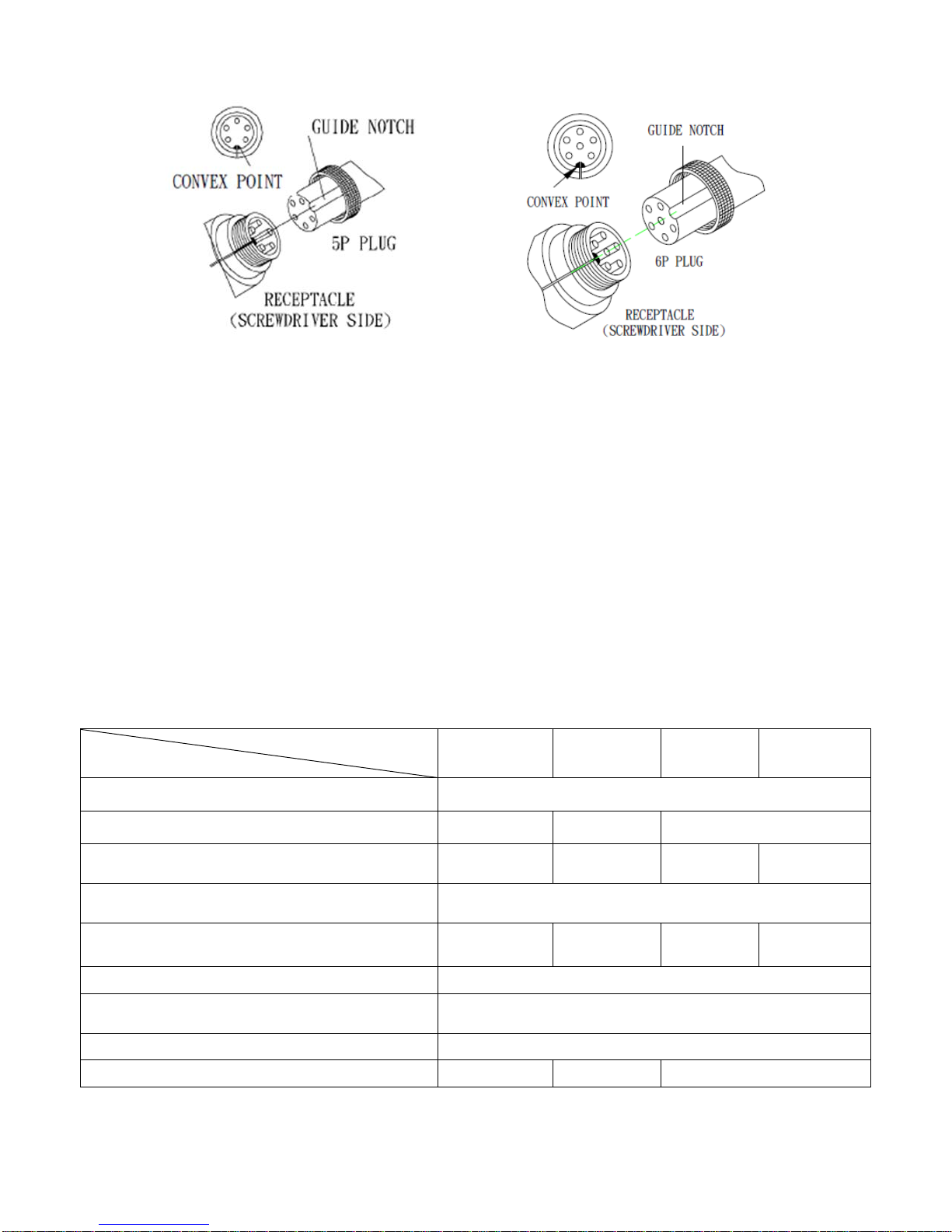
- Ensure that the connecting cable to the driver is aligned properly with the guide slot before inserting; then
twist the knob to fix the connection. Please see the picture below:
■Safety Notice
- Stop using the product if there is any unusual noise or smell. Turn off the power and contact our customer
service immediately.
- Turn off the controller when not in use. Remove the power cords from the controller for long period storage.
- The controller is for CHP electric screwdriver use ONLY. Do not use with any other tools.
4.Declaration of Conformity (CE)
We, American Hakko Products, Inc., hereby declare that the products described in this manual are in conformity
with the following Directive(s)/Standardization document(s):
Low Voltage Directive 2014/35/EU
EMC Directive 2014/30/EU
5.Product Information
■
Specification
Model
Item
APS-301A
APS-351B APM-301A APM-301C
Input Voltage
(VAC) 100~240V 、50/60Hz
Output Voltage
(VDC) 20-30 V 25-35 V 20-30 V
Soft-start (sec) N/A 0 – 1 sec N/A 0 – 1 sec
Output Voltage setting Stepless Control
Output Pin 5 pin 5 pin 5 pin 6 pin
Internal Signal Output Switch-on/Brake, Dry contact signal
External Signal Output Switch-on Signal
No. of Controlled Screwdriver 1 piece
Power (W) 60 W 59.5 W 75 W
5
Applicable Electric Screwdriver models
AT-2000B
AT-3000B
AT-4000B
AT-4000FB
AT-6000B
AT-6500B
AT-200B
AT-250B
AT-2000
AT-3000
AT-4000
AT-4500
AT-6800B AT-6000
AT-6500
AT-6800
Dimension (mm) 164X64X42 mm 172X84X46 mm
Weight (g) 300 g 380 g
AC cable length (m) 1.8 m
Safety Standards CB,CE,UL(CUL),ROHS,REACH
Accessories Adjustment tool, 2P/4P socket terminal 1 pieces, and AC cable
6.Operation
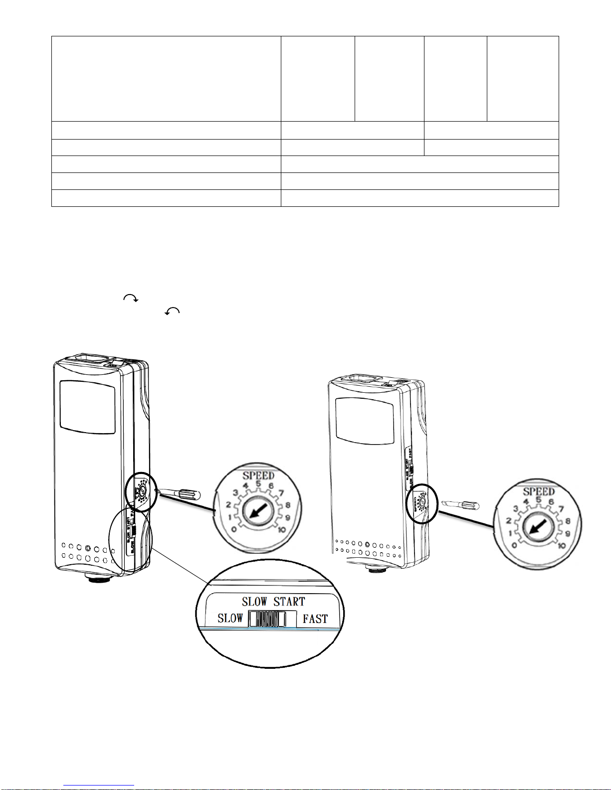
Speed setting
- Change the speed setting by turning the speed-setting screw on the side of the power supply with the small
screwdriver (standard accessory).
- Turn clockwise 010 to increase the speed.
- Turn counter-clockwise 100 to decrease the speed.
APS-Series APM-Series
Soft-start setting (APS-351B/APM-301C ONLY)
- Two-stage switch located on the side of the power supply.
- SLOW: the speed gradually increases up to full speed (approx. 1 second).
- FAST: constant speed without change.

6
Power setting and AC input socket (C13 specification)
-The input voltage of the power supply is ranged between 100-240VAC, 50/60 Hz. Please make sure to use
the correct voltage in order to avoid damage to the power supply.
Two-stage Switch Top of the Power Supply AC input socket (C13 specification)
Indicator Light
Model
Item APS-301A APS-351B APM-301A APM-301C
Green
light
Switch-on ◎◎
After switch on,
flash orange light
three times, then
turn to green
light.
◎◎
Brakes
No light
N
o DC voltage
outpu
t
◎◎◎◎
Flashing
green
Short circuit
protection ◎◎◎◎
Over power
protection ◎◎◎◎
Red light Brakes ◎◎◎◎
Flashing
red
heating
protection
(temperature set
at 75~85℃)
◎
7
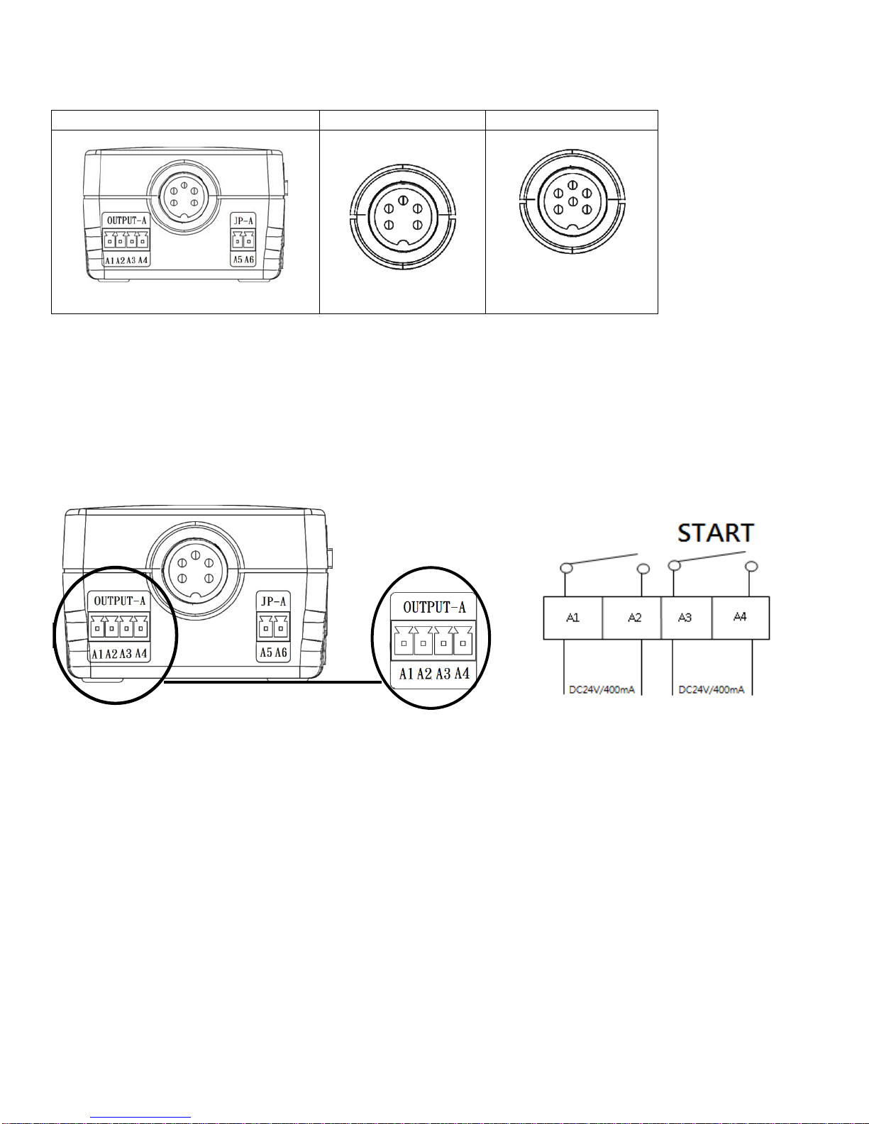
Main Output (DC) Plug
-Provides power to the electric screwdriver.
Bottom of the Power Supply 5P connection 6P connection
OUTPUT-A: Signal output terminal
-A3 & A4: “Switch on” signal output. A3 and A4 will export dry contact signal when the electric screwdriver
switched on.
-A1 & A2: “Shut-off” signal output. When the electric screwdriver has reached its set torque and stopped, no
signal will be exported.
Picture 1 Picture2
Dry contact signal
Voltage specification: DC24V/400mA MAX
JP-A: External controller use terminal (APS-301A & APM-301A ONLY)
-The power supply supports external controller to control screwdriver operation.
-Connect ON/OFF switch to JP-A terminal for external control (Forward only).
Brake

8
Screw hole for the assembly of the power supply and the balancer
-There are screw holes at the bottom of the power supply that allow the unit to be mounted on CHP spring
balancer (optional accessory) and the fixed board. Please follow the instruction below:
7.Troubleshooting
The screwdriver is not operating:
- Please ensure that the power plug is correctly plugged into the designated power source.
- Check voltage (DC) between pin 1(-) and pin 4(+). If there are no output voltage, replace the power supply.
NOTE: For 6 pin power supplies, connect pin 3 and pin 5 before measuring the output voltage.
- Check for short/open circuit in the DC connection cord.
- Please contact our customer service if the issue persists and/or other issue have occurred.
American Hakko Products, Inc.
28920 Avenue Williams
Valencia, CA 91355
1-(800)88-HAKKO(42556)
www.HakkoUSA.com
Rev 2017.11
Controller
Fixed board
55x46x5mm
Screw M3.5x10mm
Back of the Balancer
Screw M4x7mm
This manual suits for next models
19
Table of contents
Popular Power Supply manuals by other brands

Leonics
Leonics Ultimate-X 2000VA user guide

Matsusada Precision
Matsusada Precision EGD Series Basic instruction manual

Tektronix
Tektronix TM 515 instruction manual

Phanteks
Phanteks REVOLT PH-P1000PR BK01C quick start guide

Global Specialties
Global Specialties 1325 user manual

L&L
L&L ARC336700D1 installation instructions

Seasonic
Seasonic X-560 owner's manual

Elektro-Automatik
Elektro-Automatik EA-PS 724-01 manual

Strymon
Strymon ZUMA R300 user manual

ADEMCO
ADEMCO ADPOWER AD12612 installation instructions

TDK-Lambda
TDK-Lambda GENESYS 750W HALF RACK Technical manual

Moxa Technologies
Moxa Technologies DRP-240 Quick installation guide


