CHP Extra 300S User manual
Chip Hyde Products
34% Competition Series Extra 300S ARF
ASSEMBLY MANUAL

Copyright 2005 - Chip Hyde Products
Distributed by:
Chip Hyde Products Phone: (520)-458-1414
Visit the Web: www.chiphyde.com
&
Aeroworks Phone: (303) 366-4205
Fax: (303) 366-4203
Visit the Web: www.aero-works.net
E-mail: [email protected]
Warning
An R/C aircraft is not a toy! If misused, it can cause serious bodily harm and damage to property.
Fly only in open areas, preferably AMA (Academy of Model Aeronautics) approved flying sites,
following all instructions included with your radio and engine.
2

Contents of Manual
Cover page
Introduction
-Intended Use
-Warranty
Kit Contents
-Parts
-Hardware Bags
Building Instructions
-Beginning Construction
-Wing Assembly
-Elevator Servo Installation
-Stab and Elevator Assembly
-Rudder Servo Installation
-Cowl Mounting
-Motor Standoffs
-Motor Installation
-Cowl Air Lets Inlets
-Landing Gear and Skirt Installation
-Wheel Pant Installation
-Wing Attachment
-Canopy Installation
-Throttle Servo
-Belly Pan Installation
-Muffler Installation / Canister
-Fuel Tank Installation
Control Throws
C.G.
Flying
3

Introduction
Before starting the assembly process of your new 34% Extra 300S ARF, Please read through the assembly
manual carefully, and inspect all parts and hardware for imperfections or damage.
The competition series Extra 300S is a highly aerobatic airplane designed and sold by world-renowned
aerobatic RC pilot Chip Hyde who is a multiple USA National, World and TOC champion. This plane is fully
capable of both precision aerobatics and extreme 3-D aerobatics.
The Extra features rapid assembly due to plug-on wings and plug-on stabs that not only make it quick, but
easy and accurate to construct. The wings and stabilizers slide onto pre-fitted tubes and are aligned by pre-installed
anti-rotation pins. There is a minimal amount of gluing and drilling required to complete the assembly. This greatly
reduces the time to assemble and get you to the flying field.
The Extra can be disassembled and broken down into two wing panels, two stabilizer halves and a fuselage
to facilitate transportation in almost any size of vehicle. The larger the vehicle, the less you will need to remove!
Assembly at the field is greatly simplified with easy access to the inner fuse wing retention and. One ball-
wrench, a flat blade screw driver, a couple of minutes of assembly and a tank of 2-cycle gas will get you into the air.
The plane is designed for gas motors in the 100-cc category. The recommended motor is the DA 100 that is
shown in the assembly instructions. The final choice of power plant is left up to the builder.
A computer radio is recommended for the Extra. This is primarily so the Pilot can take advantage of the full
capabilities of this plane.
Intended use
This plane should not be regarded as a toy. This is an advanced aerobatic plane and is recommended for pilots who
are well beyond the trainer-stage and are comfortable with flying at least an aerobatic sport plane.
Warranty
It is important to notify Chip Hyde Products of any damage or problems with the
model immediately. If you wish to return this aircraft for any reason a 15% restock fee will
be charged to the customer. In addition the customer is responsible for all return shipping
cost and all prior shipping cost will not be refunded. Parts will be exchanged/replaced once
the original item is returned at the owner’s expense.
If you have any problems, contact CHP at (520)-458-1414
CHP cannot insure the skill of the modeler and can not direct the builder during the
construction or use of this aircraft, therefore, will not be accountable for any property
damage, bodily injury or death caused by this aircraft.
The purchaser/operator accepts all responsibility of any and
all structural or mechanical failures.
4

Kit Contents
Parts:
Canopy - unpainted
2 x Wings
2 x Ailerons
2 x Stabs
2 x Elevators
1 x Fin
1 x Rudder
1 x Fiberglass cowl
1 x Fuselage
1 x Front Hatch cover
1 x Rear Hatch cover
1 x Rear Hatch cover bottom plate
1 x 1.5” Aluminum wing-tube
1 x .5” Carbon Stab tube
1 x 10.5” x 1/4" Stab anti-rotation rod
1 x Polished Aluminum Landing gear
2 x Fiberglass Wheel pants
1 x Fiber Glass Canister tray
5

Hardware bags included:
Wheel bag
2 x wheels
2 x axles with nuts
4 x wheel collars with set screws
1 x anodized titanium tail wheel
4 x wood screws
2 x tail wheel steering springs
Landing gear
1 x tail wheel
6 x small wood screws
3 x medium wood screws
1 x tail wheel steering horn
2 x tail wheel springs
Wheel pant attachment bag
2 x wheel pant stiffeners
4 wood screws
Fuel tank and servo trays bag
1 x Fuel tank tray
2 x Rudder servo trays (different
sizes)
4 x aileron servo trays
2 x elevator servo trays
Control horn bag
8 x Anodized BB control horns
8 x 4-40 clevises
24 x Wood screws
Canopy screw bag
12 x small wood screws
Landing gear bolt bag
5 x machine screws
5 x split washers
Hatch cover screw bag
4 x machine screws
4 x flat washers
Wing attachments bag
2 x small front wood blocks
2 x large rear wood blocks
4 x anti rotation pins
4 x anti rotation pin locks
Cowl attachment bag
6 x machine screws
6 x blind nuts
Fillets bag
16 x small wood screws
2 x Upper landing gear fillets
2 x Lower landing gear fillets
2 x Cowl air lets
Screw bag
16 x small wood screws
4 x machine screws for stabs
6

Items needed to complete the Extra
100 cc Motor and Propeller
4" spinner
1 x 32 oz Fuel Tank (Gas)
Push rods
Ailerons - 4 x 2.5” pushrods
Elevators - 2 x 2.5” pushrods
Throttle -
Rudder - 1 x Heavy Duty Pull-pull 4-40 cable wires kit Dubro #
4 x aileron servos (100 Inch oz min)
2 x rudder servos (130 Inch oz min)
2 x elevator servos (150 Inch oz min)
1 x throttle servo (65 Inch oz high quality) Fast
Extension leads Wings - 2 x Y harnesses, 2 x 18”, 2 x 6”
Stabs - 2 x 36”, 2 x 12”
Throttle - 12”
Other - 2 x 12” battery extensions (depending on battery placement)
Receiver PCM
Receiver Battery
Ignition battery
2 x Charge Switches Heavy Duty
4 x 4-40 x 1/2” bolts and blind nuts for wheel pant retention.
Tools needed to complete:
Modeling knife
Electric hand drill and selection of bits
Masking tape
Phillips screwdriver (Small and medium)
Flat head screwdriver
Pliers
Allen wrenches USA and Metric.
Dremel sanding drum tool
Scissors
Wire Cutters
T pins
Ruler
Pen, pencil or fine tipped marker
Rubbing alcohol
Paper towels
Adhesives:
Thin CA
Medium CA
Thick CA
CA kicker (optional)
5 Minute epoxy
RC-56 canopy glue (optional)
7

Beginning Construction of the
Competition Series Extra 300S
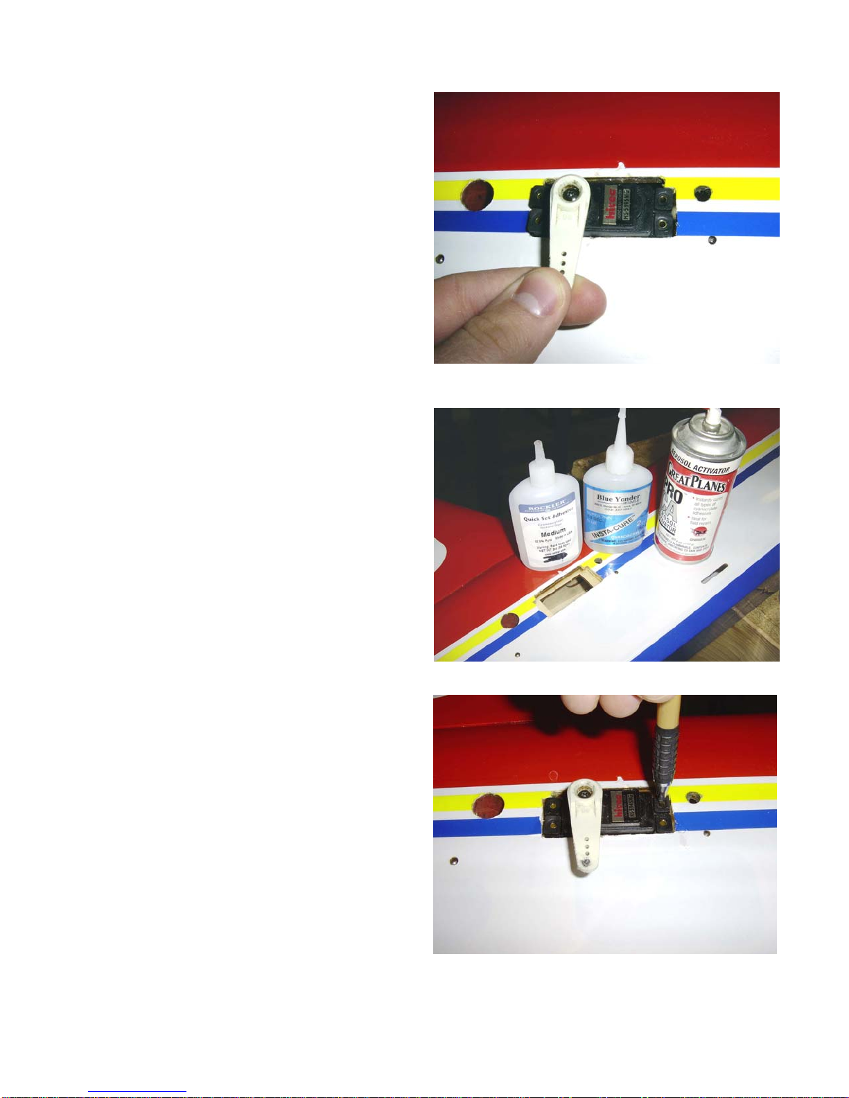
TIGHTENING AND RE-SHRINKING THE COVERING
Open your kit slowly and take care not
to damage any parts of the kit. Remove all
parts from their plastic protective covers for
inspection. Before doing any assembly or
installation of any decals it is very important
to re-shrink or re-tighten the already applied
covering. Due to the shipping process, heat
and humidity changes from different
climates, the covering may become lose and
wrinkle in the sun. If you take the time to re-
tighten the covering, you will be rewarded
with a long lasting beautifully covered
model.
Using your covering iron with a soft
sock, gently apply pressure and rub in the
covering. If any bubbles occur, your iron
may be to hot, reduce heat and work slowly.
If bubbles persist, using a small pin, punch
holes in the bubble to relieve trapped air and
reheat.
After you have tightened up the
covering, it is time to start the assembly of
your Extra 300S.
8
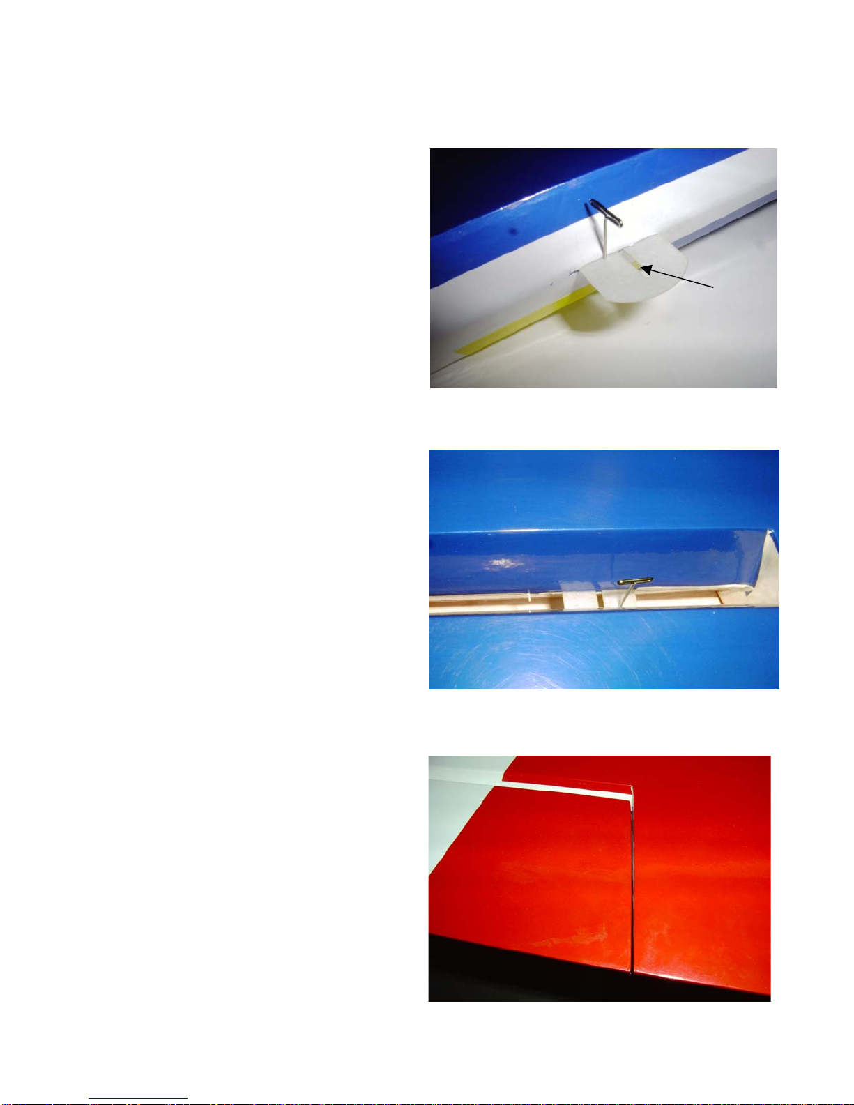
WING ASSEMBLY
1) Locate the pre cut hinge slots in the
wing and aileron. The model comes
with CA style hinges pre installed, but
not glued into the control surfaces. We
have used the provided CA hinges with
no problems. Hinge ailerons by first
pushing a T pin through the center of all
CA hinges. Make sure that slot in hinge
runs perpendicular to hinge line. This
allows CA to wick to the back of the
hinges.
Hinge Slot
2) Next, slide hinges into aileron slots, then
slide aileron onto wing making sure all
hinges go into their slot. Also, keep the
hinge line as tight as possible.
3) Be sure to leave a 1/16” gap between the
wing and the aileron at the root end to
avoid binding.
9

4) Next, place 4-6 drops of thin CA on
each side of all hinges. We also
recommend using a clear covering to
seal all control surfaces.
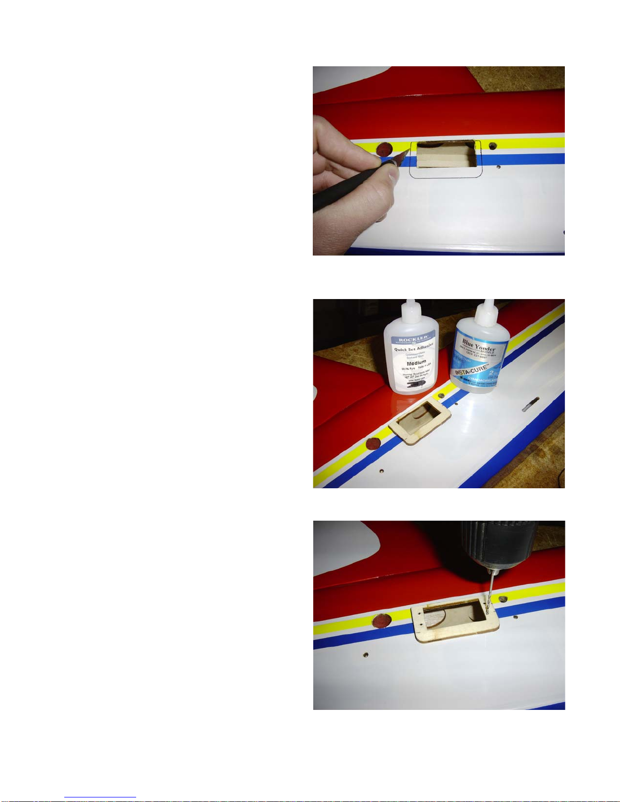
5) Locate servo locations on bottom side of
wings. Note: the pre cut slots in the
Extra are for the new Futaba 9152
servos. These servos are a little bigger
than standard size therefore, if you are
using standard size servos, we have
provided laser cut servo trays that can
easily be glued into place to
accommodate standard servo size.
6) If using the provided standard sized
servo trays, simply glue in place on top
of the pre-existing tray with either CA
or epoxy. Make sure the tray is all the
way down sitting flat against the pre-
existing tray.
10
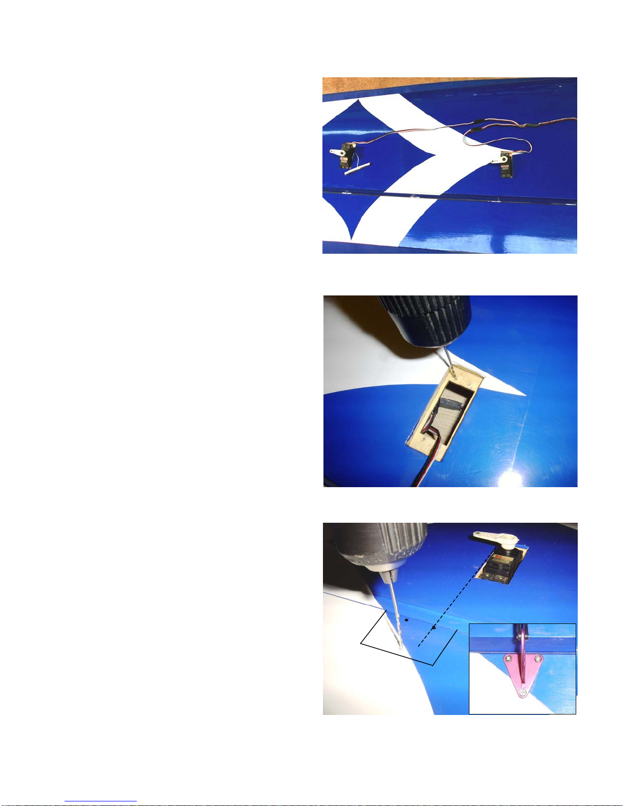
7) Attach servo extension leads to your
servos, it will be necessary to use a “Y”
harness and an 18” extension in order to
connect the two servos together and
have enough wire to exit the root of the
wing. It is important to secure the servo
connectors with tape, wire or after
market clip to be certain the leads do not
disconnected. Tie the pre-installed nylon
string to your servo wire and pull the
servo wire through the wing.
8) Test fit servos into wing so that output
shaft is toward leading edge of wing.
Mark locations for servo screws, remove
servo, and drill 1/16” pilot holes for
servo screws then harden the holes with
thin CA.
9) Reinstall servo and screw into place.
Use a ruler to mark a line on the aileron
even with the outboard edge of the servo
opening. Make sure this will be on top
of the hard wood plate in the aileron that
you can see though the covering. Now,
align the control horn so that the front
inboard hole is centered on your mark
and the front of the control horn is flush
with the leading edge of the aileron.
Mark the hole locations of the control
horn drill with a 1/16” bit.
11
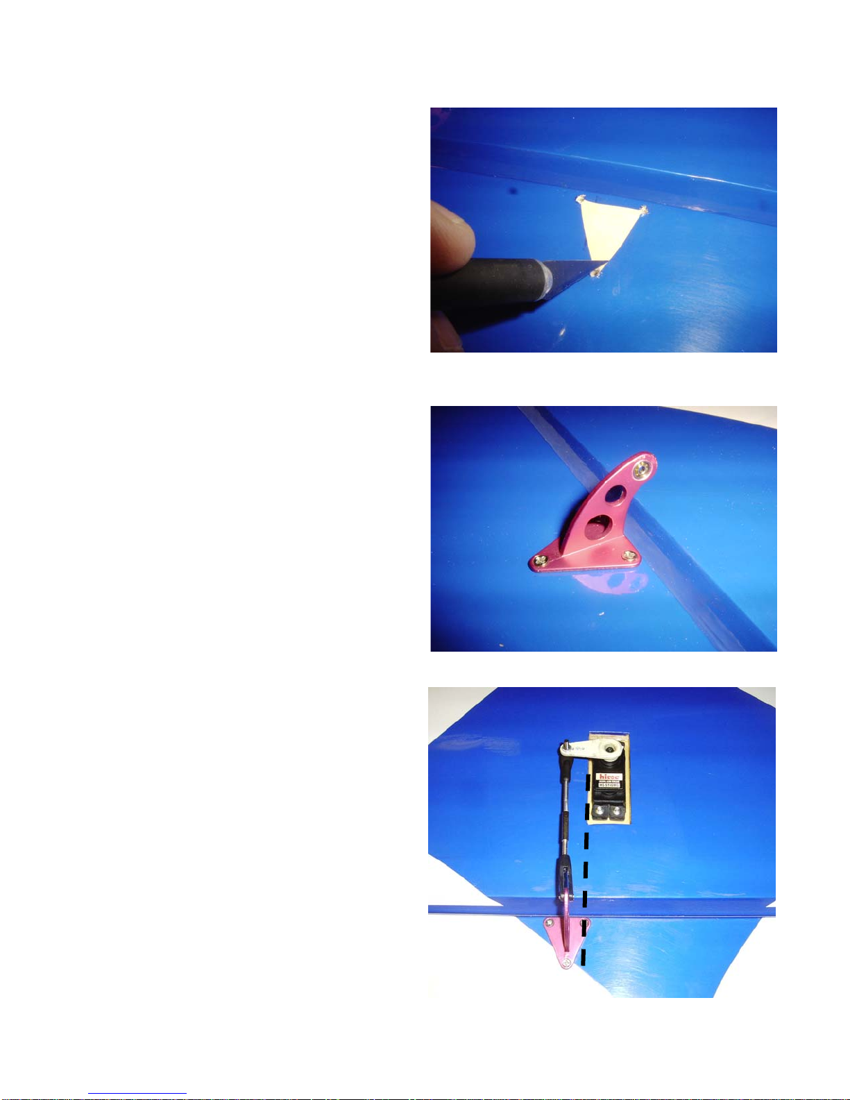
10) Now cut out the covering in a triangle
shape from your control horn screw
holes. Put a drop of thin CA in each of
the three holes to harden them. Next,
rough up the bottom of the control horn
with some sand paper so that glue will
stick to it better.
11) Now apply a thin layer of medium CA
to the bare wood in the triangle, position
control horn in place, and use three of
the provided screws to permanently
mount control horn.
12) If you are setting your plane for 3D style
flying, we recommend using larger after
market servo arms ( 1 ¼” to 1 ½”). The
pushrod selection has been left up to the
builder due to personal preference.
Special note: Remember to center all
servos prior to connecting linkages to
servo. This will eliminate any binding
when the radio is turned on.
12

ELEVATOR SERVO INSTALLATION
Note: As in the servo slots in the wings, the servo slots for the elevator servos are cut for
the new Futaba 9152 servos. Again, these servos a slightly bigger than standard size
servos, and therefore, we have provided standard size servo trays to accommodate a
standard servo. If you are using the new Futaba 9152 servos, install them as you
normally would making sure that the output shaft is toward the tail of the airplane and
the servo is as low in the slot as possible. If you are using a standard sized servo,
there are two methods of installation that this manual will illustrate. We leave it to
the builder to determine which way suits you best.
FOR ALL SERVOS: Gather the two stabs
and elevators, your two elevator servos, the
stab tube, two standard sized servo trays
(only if using standard servos), and the
aluminum stab anti rotation dowel. Use a
Xacto knife to remove the covering over the
holes in the stab and fuse for the stab
attachment bolts.
STANDARD SERVO METHOD #1
1) Test fit one servo into one of the
provided trays. Drop servo and tray into
the pre-cut slot in fuse making sure that
the output shaft of the servo is toward
the tail of the airplane and the thinner
side of the tray is toward the top of the
airplane.
Thin Side
Top
13

Align tray to fuse
Bottom Edge
TOP
2) Slide the servo and tray as far toward
the bottom of the slot as possible.
Remove elevator from stab. Insert stab
tube and anti rotation dowel into one
stab and test fit the stab by sliding it
onto the airplane (on the same side as
your servo and tray).
3) We found it necessary to remove 1/8” of
material from the top (thin side) of the
servo tray. This gives the stab enough
clearance to fit tight against the fuse.
To
p
Old New
4) Line up the inside bottom edge of the
servo tray with the inside bottom edge
of the servo slot in the fuse. Hold in
place and trace the out side edge of the
servo tray onto the fuse.
14
5) Use an Xacto knife to remove the
covering 1/16” to the inside of the line.
This is going to allow a good bond when
gluing the tray to the fuse.
6) Note: Before you glue the tray to the
fuse, you may want to cover the top and
sides of the tray with white ultra cote or
paint it. Glue the tray to the fuse with
CA. Make sure that plate is glued
securely.
7) Mark locations for the servo screws.
Drill a 1/16” pilot hole at the marked
locations. Harden these holes with thin
CA. Secure servo to fuse with servo
screws. Remember to keep the servo
output shaft toward the tail of the
airplane. Repeat steps 1-7 for other
side.
15
STANDARD SERVO METHOD #2
The second method mounts the standard size servo plate to the inside of the fuse. This requires
using a Dremel tool to enlarge the pre-existing servo slot in the fuse.
1) Test fit the servo in the fuse. Center the
servo in the slot both front to back and
up and down.
2) Trace the outline of the servo onto the
fuse side. Use a Dremel tool to enlarge
the existing servo slot to the required
size of the servo (the line you just
made). DO NOT MAKE THE HOLE
BIGGER THAN IT NEEDS TO BE!
16
3) Test fit the servo into the new slot to
make sure the servo fits all the way
inside the hole you have made.
4) Slide the standard sized servo tray into
the fuse and hold up in place from
behind (use the other elevator servo slot
hole to get your fingers into the fuse and
hold in place). Center the tray under the
slot you made. Make sure that there is
enough room for the servo screws to
attach to on each side. Glue the plate in
place with CA. Make sure the tray is
glued securely.
5) Fit the servo into the fuse. Make sure
the servo sits flat against the servo tray.
Mark the locations of servo screws and
drill pilot holes with a 1/16” bit. Again
harden the holes with thin CA
17

6) Repeat steps 1-5 to other side before
securing the servo in slot to allow you to
hold the tray in position again. Once
both plates are installed securely, attach
servos to fuse with servo screws making
sure the servo output shaft is toward the
tail of the airplane.
STAB AND ELEVATORS ASSEMBLY
1) Hinge elevators in the same manner as
the ailerons. Be sure to keep the hinge
line as tight as possible while allowing
maximum throw.
2) Also be sure to leave at least 1/16” gap
between the boost tab and the stab to
avoid binding.
18
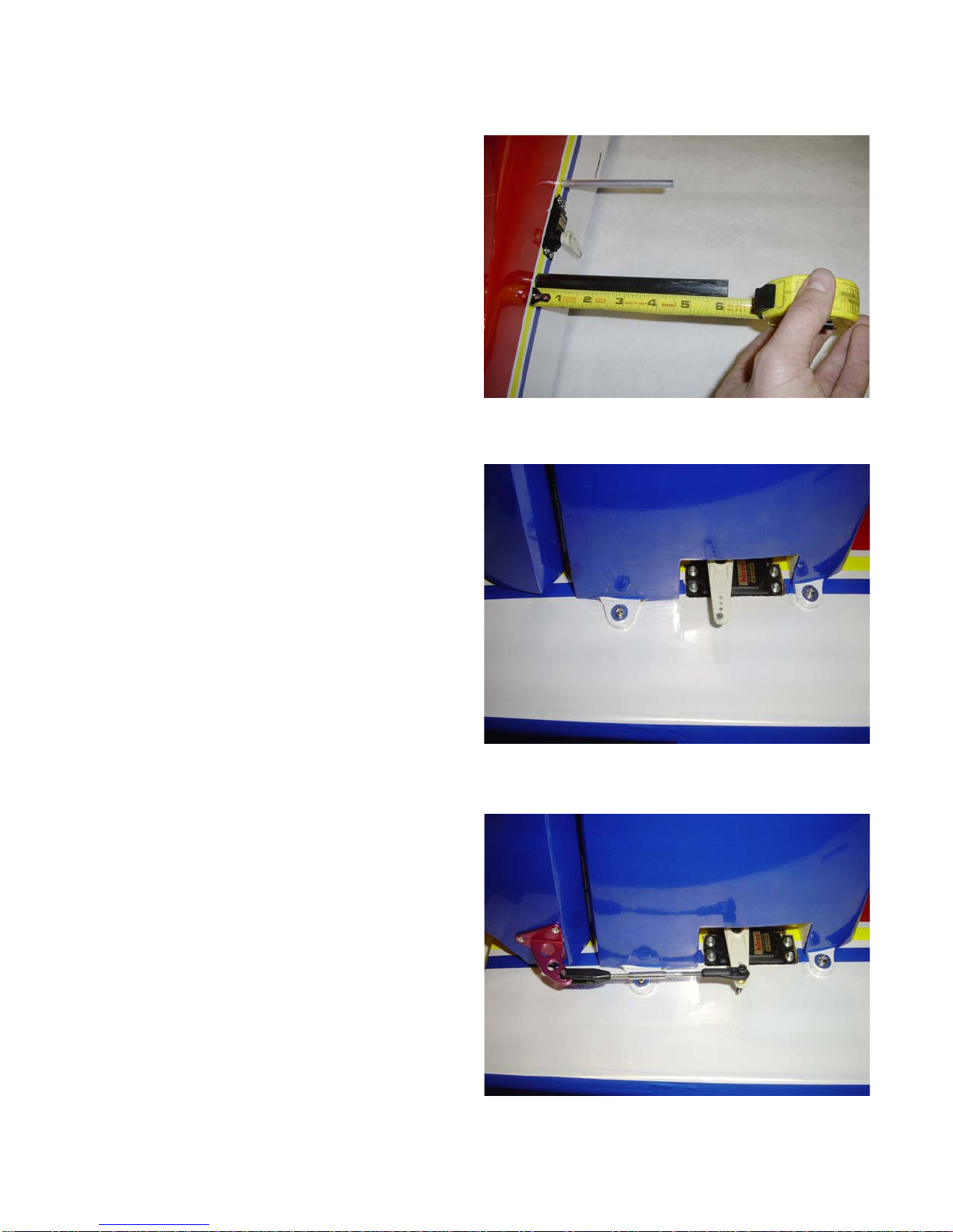
3) Next we will mount the control horn.
On the bottom of one of the elevators,
measure ¾” from the root end. This
mark is the centerline of the control
horn.
4) Next, Line the control horn up with the
leading edge of the elevator and center
the control horn over the line you just
made. Mark screw locations and drill
1/16” pilot hole.
5) Cut out triangle of covering, rough up
the bottom of the control horn, glue and
screw control horn to elevator the same
as for the ailerons. Repeat above steps
for other elevator.
19
6) Slide stab tube and stab anti rotation
dowel though fuse. Use ruler to center
both tube and dowel in the fuse
7) Slide one stab on to stab tube and dowel.
Measure to make sure tubes have not
moved. Collect the 4 bolts from the
screw bag. These screws are used to
attach the stab to the fuse. Use two of
the bolts to secure stab to fuse. Make
sure to use locktite on threads to keep
from loosening. Repeat steps to attach
other stab to fuse.
8) If you are setting up the plane for 3D
style flying, we recommend using larger
after market 1 ½”servo arms. The
pushrod selection has been left up to the
builder due to builder’s preference.
Special note: Remember to center all
servos prior to connecting linkages to
servo. This will eliminate any binding
when the radio is turned on. The control
rod in the picture was made using a 4-40
threaded rod threaded at one end, a 4-40
threaded coupler and a 4-40 swivel ball
link.
20
Table of contents
Popular Toy manuals by other brands

Eduard
Eduard F-14A exterior Assembly instructions

Miniature Scenery
Miniature Scenery Fascinating Fences instructions

Eduard
Eduard F-100F Aassembly Instructions

Great Little Trading
Great Little Trading L5172 quick start guide

Learning Resources
Learning Resources Minute Math Electronic Flash Card user manual

Fisher-Price
Fisher-Price W9737 instruction sheet


