Christ Elektronik CAM 100 User manual
Operation manual
E461506 Rev 01
Christ-Elektronik GmbH • Alpenstrasse 34 • -87700 Memmingen
Tel. +49 (0) 83 31/83 71 - 0 • Fax +49 (0) 83 31/83 71 - 99
About this manual:
Read this manual carefully for safety instructions and operating guidance before installation.
Operation manual CAM 100
Digital panel meter for Thermometer Pt100
1 Description
1.1 General
With the digital panel meter CAM 100 temperatures are measurable with Pt100 sensor. The connection of the Pt100 sensor
can take place in 2-, 3- or 4-wire technology. Two different measuring range can be programmed. Despite the small dimen-
sions the LED display can be read off even from larger distance well.
1.2 Safety instructions
This equipment is built and according to quality standards examined in accordance with European guidelines. It left the work
in safety-relevant perfect condition. The references and warning notes contained in this operating instructions must be con-
sidered around a safe enterprise to ensure. Without impairment of its working reliability the equipment can be operated
within the certified site conditions. See chapter 3. This equipment may be taken only by a specialist in enterprise, which is
familiar with the associated dangers and/or the relevant regulations.
1.3 Maintenance
All repairs of the device may only be carried out by a specialist workshop. In case it is inevitable to carry out repairs on the
opened device which is still supply voltage this may only be effected by a trained specialist who knows about the dangers
usually related to any such procedure. In case of misuse or wrong operation of the decice we do not assume any liability for
any damages that might occur.
1.4 Mounting
The equipment is to be inserted from the front into the cutout planned for it (according to DIN 43 700). Dimensions of the
cutout: 45 x 22.2 [mm]. The attachment takes place with the help of enclosed fastening parts. The tightening screws are to
be tightened mutually, until the equipment sticks. During the placement of the equipment is the radiant heat of neighbouring
devices to consider (consider permissible ambient temperature!). The electrical connection is to be made according to appro-
priate regulations (e.g. VDE 0100). Supply voltage is indicated on the type plate and is to put on the clamps 5 and 6.
2. Operation
2.1 Starting
With the digital panel meter CAM 100 the temperature - measuring range can be stopped by programming places. The deci-
mal point is likewise set with programming places.
2.2 Adjustment Pt 100
1. Select the temperature display range (see table 2) by closing the solder pads (see picture 2).
2. Connect the Pt100 Simulator to terminal block corresponding to table 1 / picture 1.
3. Bring the display to the required value for span start using the zero potentiometer “NP” (see pict. 1).
4. Apply the value for span end with the Pt100-simulator to terminal block.
5. Bring the display to the required value for span end using the gain potentiometer „V“ (see pict. 1).
6. Repeat step 3 to 5 until the display corresponds to the required measuring range.
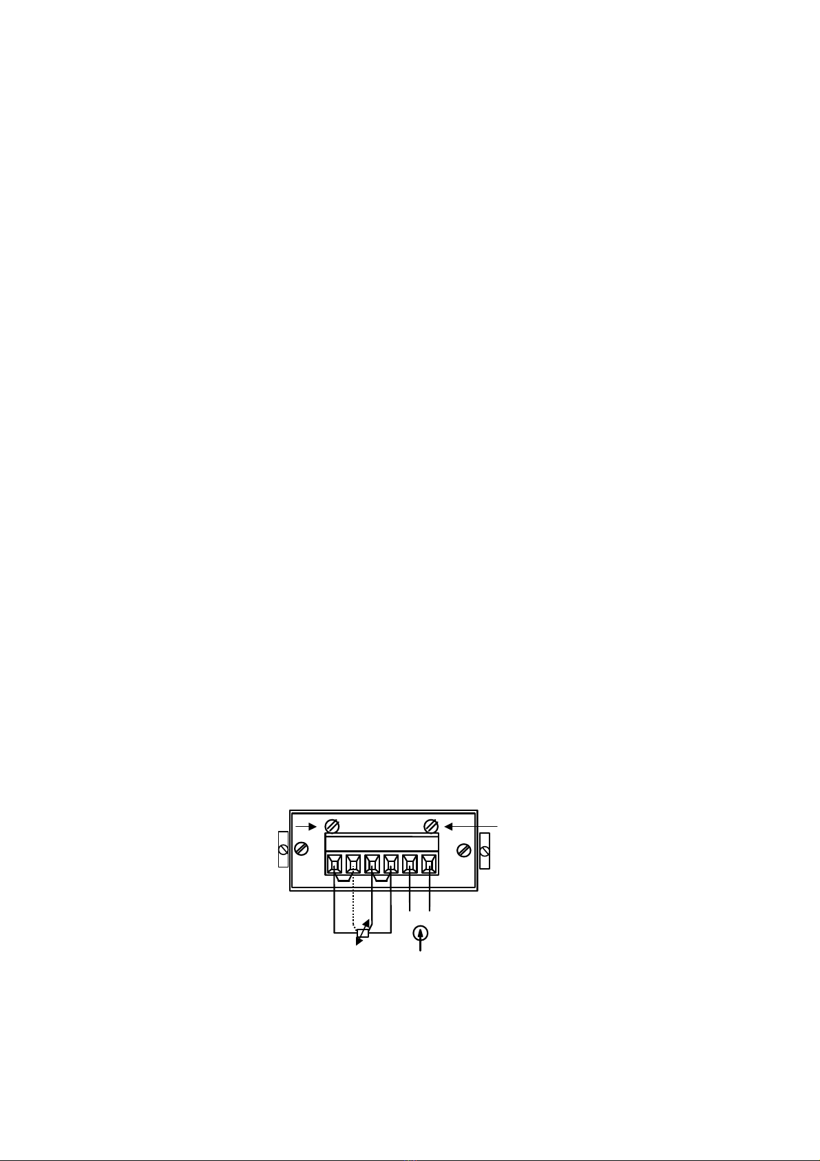
2.3 Rear view and solder pads
Picture 1: Connecting diagram
1
2
3
4
5
6
B1 B2
Bridges:
2-wire B1 and B2
3-wire B1 Pt100
4
-
wire no bridges
+ -
5, 12, 24 VDC
Supply voltage
Gain Potentio
-
meter „V“
Zero Potentio-
meter „NP“

Picture 2: Solder Pads
Picture 3: Display-ranges
1
2
3
4
5
Solder Pads
Solder Side
Table 2:
Select the temperature display range by closing the solder pads
Connection Display range Solder Pads closed
2 / 4 - wire - 100.0 ...
+ 199.9 °C 2
1)
2 / 4 - wire - 200 ...
+ 700 °C 1 and 4
3 - wire - 100.0 ...
+ 199.9 °C 3
3 - wire - 200 ...
+ 700 °C 1 and 4
1) Preset delivery configuration.
Table 1:
Connecting Pt100
Connection terminal block / bridges
4 - wire to terminal block 1, 2, 3, 4, no bridges
3 - wire to terminal block 1, 3, 4, and bridge B1
2 - wire to terminal block 1 a. 4, and bridge B1 a. B2
DP 1
DP 0
DP 2
DP 1
DP 3
DP 3
DP 2
DP 0

3 Technical data
Christ-Elektronik GmbH
Alpenstraße 34
87700 Memmingen
Telefon (0 83 31) 83 71 – 0
Fax (0 83 31) 83 71 – 99
eMail: [email protected]
Internet: http://www.christ-elektronik.de
Amtsgericht
Memmingen
HRB 9102
Subject to change !
Display
Display 7 – Segment display, 8 mm LED red
Display range ±1999 digits
Decimal point via solder bridge
Measurement range Display „1“ at overrange or sensor break
Display „-1“ at underrange
Measurement functions
Measurement range via solder bridge
Meas. method Dual Slope
Meas. rate approx. 2,5 / sec.
Response time < 2 sec. (at 100% Stepp)
Input signals Temperature
Meas. range (Resolution: 0,1 K) - 100,0 ... + 199,9 °C
Accuracy: ≤±0,2 K ±0,2 % of display value
Temp. effect: ≤±0,02 K / K (reference +25°C)
Meas. range (Resolution: 1 K) - 200 … + 700 °C
Accuracy: ≤±1 K ±0,2 % of display value
Temp. effect: ≤±0,04 K / K (reference +25°C)
Connection for 2-wire (max. 3 Ωresistance), 3- or 4-wire sensors
(each max. 100 Ωresistance)
Wire effect: 3-wire connection: ≤±0,01 K / Ω
4-wire connection: ≤±0,002 K / Ω
Distribution: 4-wire connection: Meas. range: -100,0 … +199,9 °C
Supply voltage
Supply volltage 5V
DC
4,5-5,5V
DC,
12V
DC
12 –13,2V
DC,
24V
DC
22,3 – 26,4V
DC,
galvanically separated, ripple max. 100 mV
SS,
Protection Protection against pole reversal
EMC References According to European Directive 89/336/EWG „Electromagnetic Compatibility“
and 73/23/EWG “Low Voltage Directive”. Meets with EN 50081, EN 50082 and
EN 61010 for unrestricted industrial use
Dimensions
Dimension (W x H x L) appr. 48 x 24 x 78 [mm]
Recommended panel cut-our 45 x 22,2 [mm]
Mounting depth appr. 72 mm
Material Glass-fibre reinforced Noryl, hardly inflammable,
removable front frame
Weight appr. 50 g
Panel thickness max. 5mm
Attachment via 2 attachment elements
Environment
Ambient temperature 0 ... 50 °C, no dew allowed
Protection Front panel IP 50, Terminal block IP 20 (DIN 40050, IEC 144)
Protective class II (prot. isolation)
Connections
Interconnection technology Terminal screws with wire protection for max. 1.5 mm
2
Table of contents


