Christie Roadster S+12K User manual

Roadster & Mirage S+/HD
USER MANUAL
020-100002-04


Roadster & Mirage S+/HD User Manual i
020-100002-04 Rev. 1 (12-2008)
China RoHS Compliance Information
关于中国《电子信息产品污染控制管理办法》的说明
•Environmentally Friendly Use Period
环保使用期限
The year number in the centre of the label indicates the Environmentally Friendly Use Period, which
is required to mark on the electronic information product sold in China according to the China RoHS
regulations.
本标志中表示的年数是根据《电子信息产品污染控制管理办法》(2006 年2月28 日)以及
《电子信息产品污染控制标识要求》(2006 年11 月6日)制定的、适用于在中华人民共和国
境内销售的电子信息产品的环保使用期限。
•Material Concentration Values Table
有毒有害物质含量表
Part Name 部件名称 Material Concentration
(有毒有害物质或元素)
铅
(Pb)
汞
(Hg)
镉
(Cd)
六价铬
(Cr 6+)
多溴联苯
(PBB)
多溴二联苯醚
(PBDE)
Low voltage power
supply (LVPS)
低压电源 X O O O O X
AC circuit breaker 电路开关 X O O O O X
AC Voltmeter AC 电压表 O O O O O O
Ballast 整流器 X O O O O X
AC relay 继电器 X O O O O X
Ignitor 点火器 X O O O O X
TIPM PCB TIPM 电路板 X O O O O O
Built-in keypad 控制键盘
X O O O O O
Harness/cable 连接电线/缆 X O O O O X
Three-chip panel driver 三芯驱动板 X O O O O O
High Definition Panel
Driver
高清晰度驱动
板
X O O O O O
Dual SD/HD-SDI
(DHDM) module
双信号(SD/HD-
SDI)模块
X O O O O O
Lamp Contact PCB 灯连接板 X O O O O O
LCD status display
PCB
状态显示板 X O O O O O
Blowers/Fans 吹风机/风扇 O O O O O O
Sensor 传感器 O O O O O O
Illumination optics
system
照明光学系统 X O X O O O
Projection Lens 投影镜头 X O X O O O
Auxiliary optics 辅助光学器件 X O X O O O
Mechanical enclosure* 机械附件 X O O O O O
Software CD 软件光盘 O O O O O O
Lamp 灯泡 X O X O O O
Battery 电池 O O O O O O
Optional Input Modules 可选输入模块 X O O O O O
Remote Keypad 遥控器 X O O O O O
Note:
O: indicates that the concentration value of the particular hazardous substance contained in all the homogeneous materials for this part, according to
EIP-A, EIP-B, EIP-C, is below the stipulated levels in China SJ/T11363-2006.
表示该有毒有害物质在该部件所有均质材料中的含量均在 SJ/T11363-2006 规定的限量要求以下。
X: indicates that the concentration value of the particular hazardous substance contained in all the homogeneous materials for this part, according to
EIP-A, EIP-B, EIP-C, may be above the stipulated levels in China SJ/T11363-2006.
表示该有毒有害物质至少在该部件的某一均质材料中的含量可能超出 SJ/T11363-2006 规定的限量要求。
* This part uses metallic alloys, which may contain Lead. 因该部件使用金属合金材料,故可能含有铅。


Roadster & Mirage S+/HD User Manual
Table of Contents
Roadster & Mirage S+/HD User Manual iii
020-100002-04 Rev. 1 (12-2008)
Section Contents Page
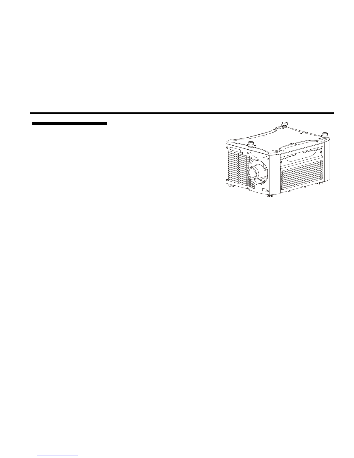
1.1 The Projectors...................................................................................................1-1
1.2 Components ......................................................................................................1-4
1.3 Purchase Record and Warranty Registration ....................................................1-4
2.1 Quick Setup ......................................................................................................2-1
2.2 Installation Considerations................................................................................2-3
2.3 Projector Position and Mounting ....................................................................2-15
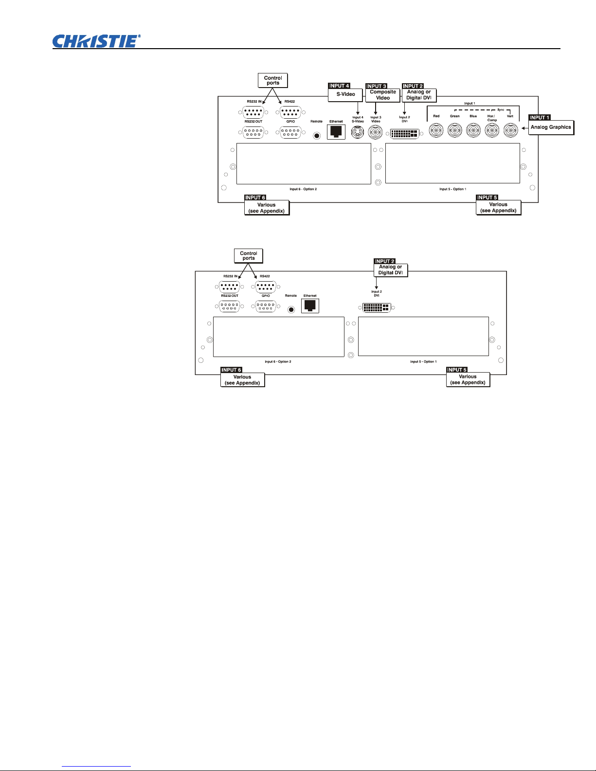
2.4 Source Connections ........................................................................................2-18
2.5 Connecting Communications..........................................................................2-21
2.6 Connecting Multiple Projectors ......................................................................2-23
2.7 Power Connection...........................................................................................2-27
2.8 Operating Orientation .....................................................................................2-28
2.9 Leveling ..........................................................................................................2-28
2.10 Zoom, Focus, and Lens Offset........................................................................2-28
2.11 Keypad Protocols and Conversion..................................................................2-29
3.1 Overview...........................................................................................................3-1
3.2 Projector Basics ................................................................................................3-1
3.3 Using the Keypads............................................................................................3-4
3.4 Navigating the Menus.....................................................................................3-12
3.5 Using Inputs and Channels .............................................................................3-16
3.6 Adjusting the Image........................................................................................3-21
3.7 Adjusting System Parameters and Advanced Controls...................................3-41
3.8 Working with PIP or Seamless Switching ......................................................3-56
3.9 Working with the Lamp..................................................................................3-59
3.10 Status Menu ....................................................................................................3-63
3.11 Using Multiple Projectors...............................................................................3-63
3.12 Remote Control of the Projector .....................................................................3-75
3.13 Error Conditions .............................................................................................3-76
4.1 Warnings and Guidelines..................................................................................4-1
4.2 Cleaning............................................................................................................4-4
4.3 Replacing Keypad Batteries..............................................................................4-5
4.4 Replacing the Lamp and Filter..........................................................................4-5
4.5 Replacing the Lens..........................................................................................4-11
5.1 Displays ............................................................................................................5-1
5.2 Lamp.................................................................................................................5-3
5.3 Ethernet.............................................................................................................5-4
5.4 3D Sync Input ...................................................................................................5-4
6.1 Specifications....................................................................................................6-1
continued…
1Introduction
2
Installation &
Setup
3
Basic
Operation
4
Maintenance
5
Troubleshooting
6Specifications

TABLE OF CONTENTS
iv Roadster & Mirage S+/HD User Manual
020-100002-04 Rev. 1 (12-2008)
A Glossary ...........................................................................................................A-1
B Remote Keypad ............................................................................................... B-1
C Serial Communication Cables.......................................................................... C-1
D Throw Distance................................................................................................D-1
E System Integration ........................................................................................... E-1
F Optional Input Modules ................................................................................... F-1
NOTE: Due to continuing research, all information in this manual is subject to change without notice.
Appendices

Section 1
Introduction
Roadster & Mirage S+/HD User Manual 1-1
020-100002-04 Rev. 1 (12-2008)
The Roadster and Mirage S+/HD Series
User Manual supports software v1.6g or
higher. The Roadster and Mirage S+/HD
Series of projectors are innovative, high
brightness DMD™ projectors that use
next generation Digital Light
Processing™ (DLP™) technology from
Texas Instruments. All models feature
compact size, rugged construction, and
integral rigging hardware, with the
Roadster Series ideal for difficult
rental/staging installations of multiple
projectors, and the Mirage Series featuring amazing stereo 3D output. A quick-
change lamp module, no-tool lens replacement, and intuitive user interface means the
ultimate in versatility and ease-of-use. These projectors provide brilliant images with
1400 x 1050 (SXGA+) or 1920 x 1080 (HD) clarity and perfect color saturation in a
wide variety of applications.
The Roadster and Mirage Series each have features for your distinct needs. The
stereoscopic Mirage projectors provide 3D solutions for power walls, simulation, and
entertainment venues. Roadster models include an additional input module as well as
integral hardware for stacking and flying up to three projectors.
This guide applies to the following projector models:
•Roadster S+12K
•Roadster S+16K
•Roadster S+20K
•Roadster HD12K
•Roadster HD18K
•Mirage S+14K
•Mirage HD12
•Mirage HD18
Roadster Series
1.1 The Projectors

Introduction
1-2 Roadster & Mirage S+/HD User Manual
020-100002-04 Rev. 1 (12-2008)
General
•DLP™ three-chip electronics with true 1400 x 1050 (SXGA+) and 1920 x
1080 (HD) native resolution
•Ten-bit digital video processing
•Single-lens design with field-interchangeable, fast-change lens – no tools needed
•Modular design for easy servicing
•Intelligent Lens System (ILS™) to save and restore lens settings
•Built-in handles and multiple rigging points
•Choice of lenses (from 0.67:1 up to 10.4:1, SXGA+ or HD), all zoom lenses
motorized
Lamps / Light Output
•Brightness (ANSI lumens)
•Roadster S+12K/HD12K or Mirage HD12 = 12000
•Roadster S+16K or Mirage S+ 14K = 16000
•Roadster HD18K or Mirage HD18 = 18000
•Roadster S+20K = 20000
•Contrast Ratio (ANSI lumens)
•450:1 ANSI
•1600-2000:1 Full Field
•LiteLOC™ for automatic constant-brightness control
•Quick change bubble-style lamp module
Inputs
There are two different types of Input face plates configurations (model dependant).
See Figure 1.1 & 1.2. These configurations may include the following inputs:
•One analog RGBHV/YPbPr input with five BNCs
•One DVI-I input for either digital RGB/YCrCb or analog RGB/YPbPr
signals
•One analog composite-video input
•One analog S-video input
•Built-in multi-standard video decoder (NTSC, NTSC 4.43, PAL, PAL-M,
PAL-N, PAL-60 AND SECAM)
•One Dual SD/HD-SDI module (standard on Roadster models only)
•Compatible with all currently used HDTV formats
For simplicity, this manual refers to the configuration in Figure 1.1 only.
Main Features

Introduction
Roadster & Mirage S+/HD User Manual 1-3
020-100002-04 Rev. 1 (12-2008)
Figure 1.1
Figure 1.2
Special Display Functions
•Auto setup with seamless cut-and-fade source switching
•Electronic brightness uniformity
•Screen-to-screen matching and blending for smooth multiple-projector displays
Communications and Diagnostics
•Two standard keypads: built-in and remote (for IR or wired control)
•Front and rear dual IR sensors
•Ethernet, RS232, RS422, and GPIO control ports
•Easy-view LED for error codes and LCD for status and error messages
•Voltmeter for monitoring AC
The projectors accept data/graphics and video input signals for projection on to front
or rear flat screens. High brightness light is generated by an internal Bubble lamp,
and then modulated by three Digital Micromirror Device (DMD) panels that provide
digitized red, green or blue color information. Light from the “on” pixels of each
panel is reflected, converged and then projected to the screen through the front lens,
where all pixels are superimposed as a sharp full-color image.
How the Pro
j
ectors Wor
k

Introduction
1-4 Roadster & Mirage S+/HD User Manual
020-100002-04 Rev. 1 (12-2008)
Ensure the following standard components have been received:
•Projector
•Infrared (IR) remote keypad and conversion cable
•Power cord (NOTE: non-detachable on Roadster S+ 20K/HD18K/Mirage
HD18)
•Roadster & Mirage S+/HD User Manual
•Using 3D in Mirage Manual (NOTE: for Mirage Series only)
•3D Stereo Sync Cable (NOTE: for Mirage Series only)
Differences Between Models
Whether the projector is under warranty or the warranty has expired, Christie’s
highly trained and extensive factory and dealer service network is always available to
quickly diagnose and correct projector malfunctions. Complete service manuals and
updates are available to service technicians for all projectors.
Should you encounter a problem with the projector and require assistance, contact
your dealer or Christie. In many cases, any necessary servicing can be performed on
site. If you have purchased the projector, fill out the Purchase Record below and keep
with your records. In addition, complete the Product Registration at the Christie
website—this will ensure that you receive all future product communications
promptly.
Purchase Record
Dealer:
Dealer Phone Number:
Projector Serial Number:
Purchase Date:
Installation Date, if applicable:
NOTE: The projector serial number is located on the projector’s rear identification
label and in the projector’s “Status” menu.
1.2 Components
Model Name Lamp
Type
Dual SD/HD-
SDI Module
3D Adjustable
Iris
Stacking
Mounts
4 Top
Eyebolts
Integral Rigging
Hardware
Roadster S+12K 2.0 kW Not Available
Roadster HD12K 2.0 kW Not Available
Roadster S+16K 2.4 kW Not Available
Roadster HD18K 3.0 kW Not Available
Roadster S+20K 3.0 kW Not Available
Mirage HD12 2.0 kW Optional Optional Optional
Mirage S+14K 2.4 kW Optional Optional Optional
Mirage HD18 3.0 kW Optional Optional Optional
1.3 Purchase
Record and
Warranty
Registration

Section 2
Installation & Setup
Roadster & Mirage S+/HD User Manual 2-1
020-100002-04 Rev. 1 (12-2008)
This section explains how to install and set up the projector. If you are familiar with the projector and want to quickly
set it up for temporary use, follow the Quick Setup instructions below. For a more complete setup, follow the
instructions and guides covered in the remaining subsections.
NOTE: The lens is not installed for shipping. Refer to 4.5, Replacing the Lens.
Follow these steps for quick setup of the projector in a standard floor mount position.
Use either the remote or built-in keypad to work with the projected image.
Position the Projector
Set the projector at the expected throw distance (projector-to-screen distance) and
vertical position. See 2.3, Projector Position and Mounting and Appendix D. Ensure
the projector is level from side-to-side (see Section 2.9, Leveling).
Connect a Source
Locate the main input panel at the rear of the projector and connector your source to
the appropriate input:
•INPUT 1 (upper right area) – RGB input via BNC connectors.
•INPUT 2 (left of BNCs) – digital or analog signals (DVI-I) from a computer.
•INPUT 3 (upper middle area) – composite video.
•INPUT 4 (upper middle area) – S-video.
•INPUT 5 (lower area) – a factory-installed Dual SD/HD-SDI module that can
accept serial digital is included on Roadster models.
•INPUT 6 (lower area) – for optional input modules (see Appendix F).
Connect to Power
The North American rated line cord is provided with each projector. For all
other regions, ensure that you are using a line cord, power plug and socket that
meet the appropriate rating standards.
Connect the projector’s line cord to the AC receptacle (Roadster
S+20K/HD18K/Mirage HD18 have non-detachable line cords) at the lower corner on
the rear of the projector, and to proper AC—note the outlet must be near the
equipment and easily accessible. Use only the line cord provided with the projector
or a power cord of appropriate ratings that comply with regional standards. Power
requirements are shown below, with complete information in Section 6.
2.1 Quick Setup
STEP 1
STEP 2
STEP 3

Installation & Setup
2-2 Roadster & Mirage S+/HD User Manual
020-100002-04 Rev. 1 (12-2008)
WARNING
Line cord replacement must be performed by qualified service
personnel in accordance with specific national electrical safety
regulations. For details, refer to the Service Manual and contact
your dealer.
•The Roadster S+12K/HD12K and the Mirage HD12 require 200-240 VAC, 50-
60 Hz, 12 amps @ 200 VAC.
•The Roadster S+16K and the Mirage S+14K require 200-240 VAC, 50-60 Hz,
16 amps @ 200 VAC.
•The Roadster S+20K/HD18K/Mirage HD18 require 200-240 VAC, 50-60 Hz,
24 amps @ 200 VAC.
WARNING
Do not attempt operation if the AC supply and cord are not
within the specified voltage and power range. Refer to Section 6.
Turn On the Projector and Lamp
1. On the projector, turn the power
breaker/switch on. The LCD Status
Display Window displays the
initializing window for 15 seconds,
and then indicates POWER OFF
(Figure 2.1).
2. Using the keypad, do one of the
following:
• Press and hold briefly to
toggle the lamp on.
• Press and release followed
immediately by .
• Press to toggle from the
off state.
The LCD Status Display Window
will display Powering Up and
then, Power On (Figure 2.1) while
the two-digit Status/Error Code
Window will display ON.
Select a Source
Using either keypad, press
Input 1
,
Input 2
,
Input 3
,
Input 4
,
Input 5
, or
Input 6
to select and display
the image for the source you connected in Step 2. The display will resize as needed
and produce largest possible image for the type of source present.
Optimize the Display
Press
Au t o
Set u p
on the built-in keypad (or on the remote keypad) to initiate an
automated process in which the projector optimizes critical display parameters such as
size, position, pixel tracking, etc., for the current source. Auto Setup can save time in
perfecting a display and you can modify the adjustments later as desired. See Section 3.
STEP 4
Figure 2.1. Turning on the projector
STEP 5
STEP 6

Installation & Setup
Roadster & Mirage S+/HD User Manual 2-3
020-100002-04 Rev. 1 (12-2008)
Lens Adjustments
•ZOOM: With the input image displayed:
•If remote keypad: Press Zoom or .
•If built-in keypad: Press Zoom or .
Hold the key down to see the effect – arrows in the display indicate
the direction of the zoom (Figure 2.2).
•FOCUS: With the input image displayed:
•If remote keypad: Press Focus or .
•If built-in keypad: Press Focus or .
Hold the key down to see the effect – arrows in the display indicate
the direction of the focus (Figure 2.3).
•LENS OFFSET: To move the image:
•If remote keypad: Press either Lens H or Lens V
(Figure 2.4).
•If built-in keypad: Press
Len s
Sh if t
and use the arrow keys.
Image Adjustments
Press
Menu
or (remote) to access display parameters described in Section 3.
Although this projector delivers a high-brightness, high-quality output, the final
display quality could be compromised if the projector is not properly installed. This
subsection discusses issues you should consider before proceeding with a final
installation. Even if you do not intend to use the projectors in a fixed and permanent
installation, the following information will help you to better understand what you
can do to enhance display performance.
For any new installation, you will likely have to safely lift or hoist the projector into
place. Keep in mind the following guidelines for safety.
Lifting
All models include handles for convenient hand transport only, such as when a
projector is lifted from a shipping container to a table. Note the following:
•The handles are intended to support the weight of one projector only.
•The handles are intended to support a projector for a brief time only.
•The handles are not safety points, nor points from which to hoist or suspend the
projector.
STEP 7
Figure
2.2
Figure
2.3
Figure 2.4
Ste
p
8
2.2 Installation
Considerations
Lifting, Hoisting,
and Stackin
g

Installation & Setup
2-4 Roadster & Mirage S+/HD User Manual
020-100002-04 Rev. 1 (12-2008)
WARNINGS
The handles can not support more than ONE projector.
Do not use handles for extended time periods.
Do not use the handles as safety points, or as points from which
to suspend or hoist the projector.
Hoisting
Four integral rigging points on the top of the projector (Figure 2.5) and eight on the
bottom (Figure 2.6) enable either upright or inverted hoisting. For either orientation,
hoist an individual projector, or up to three projectors in a stack.
Figure 2.5. Top Rigging Points
RULES FOR ALL HOISTING:
•Use at least four rigging points for hoisting
up to three projectors.
•Connect safety cables, and rigging
equipment to the designated locations on
the projector.
•Use hoisting and rigging equipment
suitable to your application such as clamps,
cables, eyebolts, or straps, and which
accommodate the load rating. All integral,
metric hardware on the projector accepts
an M12 thread only.
•Never hoist a projector by its feet, handles,
or any other component (Figure 2.7).
Figure 2.6. Bottom Rigging
Points

Installation & Setup
Roadster & Mirage S+/HD User Manual 2-5
020-100002-04 Rev. 1 (12-2008)
WARNING
Use metric hardware only.
Never force incompatible threads.
IMPORTANT
Remove the lens before hoisting a projector.
WARNING
Never hoist a projector by its feet,
handles, or any other component.
Figure 2.7. NEVER Use Handles for Hoisting or as Safety Points
This procedure applies to one or more projectors. To hoist a stack, first stack two or
three projectors according to the stacking procedure included in this manual. Never
stack or hoist more than three projectors together.
Remove lens (recommended)
Remove the projection lens to prevent possible damage during hoisting. See 4.4,
Replacing the Lamp and Filter.
Retract feet
If the projector is inverted, retract the adjustable feet to prevent the hoisting hardware
from getting caught.
Hoistin
g
Procedure
STEP 1
STEP 2

Installation & Setup
2-6 Roadster & Mirage S+/HD User Manual
020-100002-04 Rev. 1 (12-2008)
Attach safety cables
Attach a safety cable to each of the two eyebolts
mounted on the bottom of the projector (Figure 2.8).
WARNING
Always use at least two safety cables for any
hoisting.
WARNING
Attach safety cables to the two eyebolts.
NOTE: When hoisting a non-inverted projector or
stack, add two safety eyebolts in the front and rear
threaded holes provided on the top of the projector.
Ensure the eyebolts have an adequate rating for the
load. Secure safety cabling to both eyebolts.
Attach rigging hardware
Secure your rigging components
to the appropriate rigging
points—eight sliding points are
provided on the bottom. Tighten
the nut at each required location
(Figure 2.9) to prevent sliding.
NOTES: 1) Use at least four
rigging points for all hoisting.
2) Use straps, clamps or cabling
with load capacity adequate for
the total projector weight. See
Section 6. 3) Do not join the
rigging straps or cables to a
common point—keep separated
as shown.
WARNINGS
• Maximum stack = three
projectors.
• Stack first, then hoist.
NOTES: 1) Requires stacking hardware provided standard with Roadsters only.
Available separately for Mirage Series. 2) Installation requires at least two people.
Roadster and Mirage projectors can be stacked in either the upright or inverted
position. Do not mix orientations—i.e., inverted with upright—in a stack. Secure a
maximum of three projectors with the stacking mounts as described below.
Figure 2.8. Attach Safety
Cables
NOTE: ADD EYEBOLTS (2)
IF NON-INVERTED
STEP 3
STEP 4
Figure 2.9. Using the Rigging Hardware
Stackin
g
Procedure

Installation & Setup
Roadster & Mirage S+/HD User Manual 2-7
020-100002-04 Rev. 1 (12-2008)
WARNING
Do not stack more than three projectors.
WARNING
Christie stacking hardware required. The top
projector could slide off and cause injury or death.
WARNING
Never carry a stack.
Position the projectors
Place the projectors to be
stacked on a secure table or
cart.
•Place one projector on its
side to access its
adjustable feet and
stacking legs (Figure
2.10).
•Orient the other projector
in either upright or
inverted position as
required (remember,
each projector in a stack
must be in the same
orientation).
Fully retract the four
adjustable feet
Retract each foot as far as possible by turning it clockwise.
•If upright – retract the feet on top projector.
•If inverted – retract the feet on bottom projector.
STEP 1
Figure 2.10. Adjust the Feet
STEP 2

Installation & Setup
2-8 Roadster & Mirage S+/HD User Manual
020-100002-04 Rev. 1 (12-2008)
Extend the three stacking legs
Extend the stacking legs by turning them so
that at least one inch of thread is visible on
each. This clearance accommodates the up-
or-down movement for aligning the images
from the stacked projectors. Extend all three
legs equally (Figure 2.11).
•If upright – extend legs on top projector
(shown).
•If inverted – extend legs on bottom
projector.
IMPORTANT: Extend the stacking legs
equally by at least 1 inch.
Loosen the rear stacking leg nuts
On the rear stacking legs, loosen the nuts so
the legs have some lateral movement for
easier alignment with the stacking mounts on the other projector.
Figure 2.12. Loosen 2 Nuts
•If upright – release on top projector.
•If inverted – release on bottom projector.
Figure 2.11. Extend 3 Stacking
Legs
(UPRIGHT STACK SHOWN)
STEP 3
STEP 4

Installation & Setup
Roadster & Mirage S+/HD User Manual 2-9
020-100002-04 Rev. 1 (12-2008)
Release and remove three safety pins
The safety pins must be removed from the
stacking mounts so that the stacking legs can fit
into the mounts (Figure 2.13).
•If upright – remove the pins from the mounts
on the bottom projector.
•If inverted – remove the pins from the
mounts on the top projector.
Place top projector on bottom projector
WARNING
Minimum of two people required.
With one person on each side, lift the top projector on to bottom projector, aligning
all three stacking points between projectors. The legs should fit inside the stacking
mounts.
Align the holes in the three stacking mounts and three stacking legs.
On each stacking mount, turn the adjusting wheel slightly until the hole in the top
portion of the mount lines up with the hole in the stacking leg (Figure 2.14).
NOTE: You can increase leverage by using a screwdriver in the holes.
Figure 2.14. Align Holes in Mounts and Legs, and LOCK with Pin
Figure 2.13. Remove Safety
Pins
STEP 5
STEP 6
STEP 7

Installation & Setup
2-10 Roadster & Mirage S+/HD User Manual
020-100002-04 Rev. 1 (12-2008)
Insert three safety pins and LOCK all.
WARNING
Critical Safety Procedure.
At each of the three stacking points, insert the safety pin fully through the holes in the
stacking mounts and stacking legs (Figure 2.14). Ensure that each pin is fully inserted to
engage the safety lock and secure the projectors together. Failure to engage the safety
lock could cause the projectors to separate and result in injury or death.
WARNING
Failure to engage the safety lock could cause the projectors to
separate and result in injury or death.
Leg Nuts
Before hoisting, firmly tighten the nuts on the two rear stacking legs (Figure 2.14). If
you are ready to align the projectors to one another, leave these nuts slightly loose
until after the alignment.
Repeat STEPS 1–9 for a third projector.
WARNING
Never stack more than three projectors.
Stacked projectors must be correctly aligned to one another so that the resulting
display is optimized and as sharp as possible. If you are also hoisting the stack, hoist
the stack into place first and then align. Lock all stacking hardware into place to
maintain your alignment.
IMPORTANT
Ensure the stacking legs are extended at least one inch and are
slightly loosened. Refer back to Figure 2.11.
Before You Begin
•Always align to the fixed projector. In floor-mount or table-mount (i.e., non-
hoisted) stacks, you will align to the bottom projector as shown in drawings
below. In hoisted stacks, align to the top projector.
•Leg nuts must be loosened before alignment; otherwise the stacking mounts will
not turn and allow movement of the projector.
Position the first image (fixed projector)
Position the fixed projector’s image as desired and align the other image(s) to it as
described below.
Display the grid test pattern
To distinguish each image, enable “Red” for one display and “Green” for the other.
See 3.3, Using the Keypads if you need help enabling colors.
Adjust zoom and focus
Minimize each projector’s zoom and images are in focus.
STEP 8
STEP 9
STEP 10
Ali
g
nment Procedure
STEP 1
STEP 2
STEP 3
Other manuals for Roadster S+12K
4
This manual suits for next models
7
Table of contents