Chromalox DirectConnect User manual
1
Installation and
Operating Instructions
Chromalox DirectConnectTM
High Voltage Converter System
PK526
Doc Rev: 13 AUG 2022
Software Rev 2.60

2
Table of Contents
A: INTRODUCTION AND SAFETY................................................................................................................3
B: RECEIPT, HANDLING, STORAGE and INSTALLATION....................................................................6
C: COMMISSIONING......................................................................................................................................11
D: OPERATION...............................................................................................................................................12
E: INSPECTION and MAINTENANCE........................................................................................................16
FASTENER TORQUES..................................................................................................................................18
ANNEX 1: HMI SCREENS............................................................................................................................19
ANNEX 2: ARC CONTROL SHROUD........................................................................................................38

3
A: INTRODUCTION AND SAFETY
The DirectConnectTM Converter System
manual uses this symbol to alert personnel
to potential hazards that may damage the
equipment.
The DirectConnectTM Converter System
manual uses this symbol to alert personnel
to potential hazards that may cause injury
or death.
__________________________________________________________________________
1...General
1.1 Scope
This manual provides instructions for receiving, handling, storage, installation, startup
(commissioning), operation, and maintenance (including troubleshooting) of Chromalox High
Voltage Converter Systems designed and built to IEC or UL standards.
__________________________________________________________________________
2...Introduction
2.1 Key Safety Practices
ALL PERSONNEL WORKING
ON HIGH VOLTAGE
ELECTRICAL EQUIPMENT
MUST ADHERE TO ALL
NATIONAL AND LOCAL REGULATIONS,
CODES, AND STANDARDS.
ONLY SUITABLY QUALIFIED AND
EXPERIENCED PERSONS, WHO ARE
FAMILIAR WITH THIS EQUIPMENT, AND
THE WORK THEY ARE TO DO, SHOULD
CARRY OUT INSTALLATION,
COMMISSIONING, OPERATION, OR
MAINTENANCE OF THIS CONVERTER
SYSTEM AND THE ASSOCIATED
HEATER.
SUCH PERSONS SHALL ADHERE TO
PROPER HIGH VOLTAGE SAFETY
PROCEDURES, INCLUDING THE USE OF
APPROPRIATE PERSONAL
PROTECTIVE EQUIPMENT (PPE).
FAILURE TO ADHERE TO ANY OF THE
ABOVE MAY RESULT IN EQUIPMENT
DAMAGE, OPERATING LOSSES,
INJURY, OR DEATH. CHROMALOX
WILL NOT BE LIABLE FOR FAILURE TO
ADHERE TO ALL GOVERNING
REGULATIONS, CODES, STANDARDS,
SITE PROCEDURES AND INFORMATION
GIVEN IN THIS MANUAL.
IF IN DOUBT, CONTACT CHROMALOX.
2.2 Description
An MV DirectConnectTM Converter System will
be made up of multiple ‘Sections’.
The primary load control element is the three-
phase line-commutated semiconductor (SCR)
power ‘Converter’ section. This contains three
SCR ‘Stacks’, each with three pairs of SCRs
connected in series. Each pair of SCRs is
mounted in ‘anti-parallel’ so that one SCR can
control the current flowing in one direction, and
the other can control it when the current is
flowing in the opposite direction.
The Converter section also contains an output
voltage monitoring VT, three load current CTs,

and a CT connected around all three phases to
measure residual current leakage to earth
[ground]. It will usually also contain the MV
Load Terminals, though these could be
supplied in a separate section. The Converter
switches the supply voltage in such a way as to
control (reduce) the amount of voltage that
reaches the heater to provide the heating
needed.
Power for the Converter is fed from the
‘Controller’ section. This contains an MV
Disconnector Switch, fully rated Type E MV
fuses, an MV Contactor, Inductors, and an input
voltage monitoring VT. It can also contain a
power supply Control Power Transformer
(CPT), and the MV Supply Line terminals.
Cooling for the Converter stacks is provided by
a door mounted fan (for NEMA 1), or a side
mounted Heat Exchanger (for NEMA 4). The
Inductors, which are connected in circuit
between the Contactor and the SCR stacks,
limit the rate of rise (di/dt) of current flowing into
the SCRs.
If the incoming MV supply line terminals are not
mounted in the Controller section, a separate
‘Direct-on-Line’ (‘DOL’) section will be provided
for these terminals.
If multiple Heaters are to be fed from a
Converter, and separate switching control is
required for each Heater, ‘Load Switching’
section(s) will be provided, each with up to two
Contactors, and associated load terminals.
If the total Heater load exceeds the maximum
that can be supplied by the Converter, the
Converter System will be equipped with
additional ‘Stepper’ sections that work in
sequence with the Converter to ramp the
Heater load up to the level required. ‘Stepper’
sections each have a Disconnector Switch, MV
fuses, and output Power and Dry-out
Contactors.
LV control is mounted in a separate ‘LV
Compartment’ that is mounted on the front door
of the Converter.
The doors for the various sections, and for the
Low Voltage compartment can be locked closed
using key locks provided in the door handle.
The Disconnector Switches mentioned above
each provide an isolation gap between the
Supply/Line power and the associated
Heater(s). They can be padlocked open. A
window is provided for each Disconnector so
that its status can be verified visually.
The Disconnector and the Heater junction
box(s) can be equipped with a key inter-locking
system intended to prevent opening of certain
compartments until specific conditions are met.
For example, the Heater junction box lock may
be equipped with a key that is captured in the
Disconnector Switch mechanism and is not
released until the Disconnect Switch is open.
Secondary compartmentalization may be
provided, in which the Disconnector(s) is
segregated in its own compartment within the
Controller or Stepper section. This
compartment has its own door, and with this
door closed, in some regions / applications, if
the Disconnector is open access to the
associated MV fuses mounted in that section, is
possible for replacement with MV power still
connected to the primary side of Disconnector.
Appropriate PPE must be worn. However, it is
strongly recommended that, if at all possible,
the main incoming supply be switched off and
locked off upstream of the Converter System
before such work is carried out.
2.3 General Safety Principles
All connections should be considered energized
until proven to be de-energized, and until every
possible precaution has been taken to ensure
that they stay de-energized until work is
complete.
Suitable visible warning devices should be
placed around the Converter Systems, at a
suitable distance from the equipment, if work is
necessary when the System is still live.
Components inside the Converter System may
stay physically hot for some time after supply
has been switched off. SCR snubber
capacitors will self-discharge in less time that is
needed to remove the red-board covers.
2.4 De-energizing, and Earthing /
Grounding
BEFORE WORKING INSIDE
THE EQUIPMENT, CONFIRM
THAT ALL POWER HAS BEEN
TURNED OFF, LOCKED OFF,
AND PREFERABLY EARTHED
[GROUNDED] AT ALL POINTS OF LOW
AND HIGH POTENTIAL, ON BOTH THE
SUPPLY LINE AND LOAD SIDE
CIRCUITS, AS REQUIRED / PERMITTED
BY ALL CODES AND STANDARDS.
Never assume: Use a properly rated voltage
sensing device to verify that power is off.
The Disconnector Switches mentioned above
provide an isolation gap between the Supply
Line power and the associated Heater(s). They
can be padlocked open. A window is provided
so that its status can be verified visually.
NOTE: INCOMING POWER SUPPLIES,
TERMINALS, AND CONNECTIONS TO THE
DISCONNECTOR SWITCHES ARE STILL
LIVE WHEN THE DISCONNECTOR IS OPEN
The Disconnector and the Heater junction
box(s) can be equipped with a key inter-locking
system intended to prevent opening of certain
compartments until specific conditions are met.
For example, the Heater junction box lock may
be equipped with a key that is captured in the
Disconnector Switch mechanism and is not
released until the Disconnect Switch is open.
The VTs and CPT mentioned in the
descriptions above will all back feed high
voltage onto the MV circuits if an auxiliary LV
control is connected to their secondary(s).
Therefore, care must be taken when connecting
any test equipment to the LV circuits, and the
voltage free status of the MV circuits must be
verified by testing, and preferably ensured by
connecting a cable from each circuit to the
earth / ground before any work starts.
2.5 Design Purpose
This equipment was specifically designed for its
intended purpose and should not be used for
any other application without a complete re-
evaluation by the manufacturer. The operator
should ensure these instructions are kept with
the equipment to prevent any use for which the
equipment has not been designed.
2.6 Complete System
The Chromalox DirectConnectTM system is
comprised of both a Chromalox MV
Converter System and a Chromalox MV
Heater. One may not be employed without
the other. All written and implied warranties
are voided if one DirectConnectTM
component is used without the other.
2.7 Startup/Commissioning
All Chromalox DirectConnectTM MV Converter
Systems MUST be commissioned by
Chromalox Service Personnel. All written and
implied warranties are voided if non-Chromalox
Service personnel are utilized for
DirectConnectTM System commissioning.
__________________________________________________________________________

6
B: RECEIPT, HANDLING, STORAGE and INSTALLATION
3...Receiving & Handling
3.1
Care should be exercised when moving
Converter Systems as they are heavy and can
tip over. Do to attempt to handle systems
without securing properly and using only proper
equipment capable of handling heavy loads.
3.2
When first received, inspect for shipping and
handling damage. Proceed only if there is no
visible damage.
3.3
Ensure that lifting equipment can handle the
weight of the system.
3.4
Keep the system secured to prevent distortion
of the frame during moving and to minimize
tipping.
3.5
Exercise care during any movement and
placement operations to prevent falling or
unintentional rolling or tipping.
_________________________________________________________________________
4...Storage
4.1.1. Any system that is not installed and
energized immediately should be stored in a
clean, dry space where a uniform temperature
prevents condensation. It should be stored in a
heated building with adequate air circulation
and protected from dirt, pollutants (especially
conductive dust, salt laden air, and Hydrogen
Sulfide), water, rodents, insects and mold. The
system should be stored off the ground. Doors
should never be left open.
4.1.2. Shipping containers are temporary
protective covers. The system should not be
stored outdoors for more than 24 hours. If the
system must be stored outdoors for longer
periods it must be protected from the outdoor
elements with appropriate coverings.
4.2 Short Term Storage
4.2.1. In non-humidity-controlled environments,
the anti-condensation heaters (if fitted) must be
energized, equivalent temporary heating
sources must be provided, or desiccant must be
used to prevent condensation on interior
surfaces.
4.2.2. Electronic components can be damaged
if stored at low temperatures. If the system is to
be stored in an environment of less than 0oC
[32of], the internal heaters (if fitted) must be
energized, or equivalent temporary heating
sources must be provided.
4.2.3. Unless the system is designed for use in
direct sunlight, it should be stored away from
direct sunlight, or be suitably covered.
4.2.4. Once the system is taken out of storage,
all desiccant, internal packing, caps, plugs,
wrappings, etc. must be removed just prior to
the equipment being placed into operation.
4.3 Long Term Storage
4.3.1. For long term storage, in addition to the
above precautions, it is recommended that the
entire system should be heat sealed in plastic
barrier bags with the proper amount of
desiccant included.
Converter Systems in long term storage should
be inspected periodically for any signs of
deterioration.
4.4 All written and implied warranties
are voided if these storage guidelines
above are not followed.
__________________________________________________________________________

7
5...Installation
Precautions & Warnings
READ AND UNDERSTAND
SECTION A ABOVE BEFORE
CARRYING OUT THE WORK
DETAILED BELOW
5.1 Preparations
5.2.1. The Heater skid & Converter System
should be adequately protected against
mechanical damage, extreme temperatures and
other adverse environmental conditions.
5.2.2. Ensure that all precautions are taken
regarding the weight of the equipment. Lifting
equipment should have capacity for the given
weight.
5.2.3. The foundation must be sufficiently
strong to withstand the load of equipment and
should be flat.
5.2.4. Converter Systems should be inspected
for foreign material, and the entire system
should be cleaned before startup.
5.2.5. General safety precautions listed in the
plant safety procedures should be closely
complied with to prevent injury to personnel or
damage to equipment.
5.2.6. Ensure that personnel responsible for site
safety and others in the vicinity are aware that
work is being undertaken and required post
warning notices. Ensure that the appropriate
PPE and clothing is worn. Take all required
precautions if working at above ground level.
5.2.7. Where possible hazards have been
eliminated or reduced as far as is reasonably
practicable by design, but the additional
warnings listed below should be followed to
ensure continued safe use
5.2. Mechanical Installation
5.2.1 Converter Systems are shipped on heavy
duty pallet(s) and can be lifted and moved using
forklift trucks, or heavy-duty rollers.
5.2.2 Converter Systems may be shipped in
one or more Transport Units / Shipping
Sections. Each section is equipped with lifting
angles allowing the System or Transport Unit to
be removed from the pallet. All four lifting
angles in the corners of the System should be
used.
For outdoor installations these lifting angles
should be removed, and the fasteners should
be replaced. Sealing washers, shipped with the
System, should be installed under the heads of
the fixing screws before reassembly. Do not
discard the lifting angles. They may be needed
for lifting or moving the System in the future.
5.2.3 All lifting should comply with local codes.
In particular, if lifting chains are used, they
should be attached individually to each lifting
eyes (i.e. not in a loop run through 2 or more
lifting eyes), and there should be an angle of at
least 45 degrees between the lifting chain and
the roof of the Converter System.
On IEC Systems, if adequate space is not
available above the Converter System for a
lifting crane to be used, and access will be
available behind the System once installed, the
plinth front and rear bottom plates may be
removed, and a fork truck or palette truck(s)
may be used to move the System into place.
Very great care must be taken if this form of
movement has to be used to avoid damage to
the plinths. The front and rear bottom plates
must be replaced once installed as they form a
key part of the structural integrity of the base.
5.2.4 Typically a minimum of 300mm [1ft] is
necessary to the sides and rear of the
Converter System for cooling, and 1.8m [5.9ft]
is necessary at the front to allow enough space
for personnel to pass in front of an open door.
The ceiling above Systems that are not Arc-
Resistant must be at least 2.5m [8.2ft] above
the floor to allow 300mm [1ft] of space above
the roof for cooling.
IEC Arc Resistant Converter Systems are for
internal use only. The ceiling above these
Systems must be at least 4.4m [14.4ft] above
the floor to allow 2m [6.6ft] of space above the
roof for explosive products to exit.
Do not install Arc Resistant Systems below
catwalks or other elevated access routes.
To ensure that water does not enter the System
from below, adequate drainage should be
provided around the System, and in cable
trenches. Cable ducts should be sealed.
Avoid exposure to salt air, hydrogen sulfide,
excessive dust, dripping water, falling dirt, or
other similar conditions.
The equipment is not designed for seismic
shock, or nuclear radiation hazards.
5.2.5. Once the Converter System is in place, it
should be secured to the foundation by suitable
means. On IEC Systems, the plinth front and
rear bottom plates may be removed to access
the plinth mounting holes. These plates must
be replaced once the System is secured as
they form a key part of the structural integrity of
the base. On UL Systems, access to mounting
holes can be found inside the enclosures.
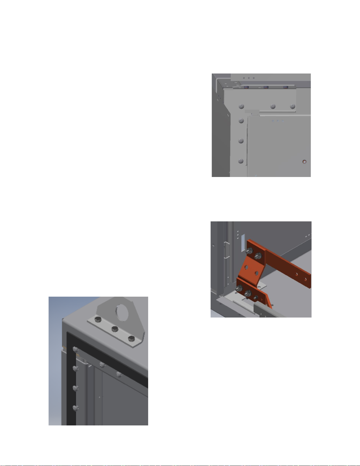
5.2.6 If IEC Converter System are supplied in
shipping sections that have to be assembled
together on site, the fasteners that are to be
used to secure the shipping sections together,
will be fastened to the left hand section of the
each shipping section at the shipping split.
There will be 24 such fasteners plus any
associated washers at each shipping split, 6 per
corner as shown below. Tighten the screws to
71lbs in [8.0 Nm].
IEC sections must be brought together, and the
fasteners (and any associated washers) must
be installed from the inside of the section to the
left of the slit through into holes where the
fasteners were originally installed.
The ground bar link that connects the ground
bars in the IEC sections either side of the
shipping spilt will be mounted such that it faces
into the section.
It should be detached from the vertical copper
stub that it is attached to, turned through 180
degrees, and reassembled such that it passed
through the slot in the adjacent steelwork.
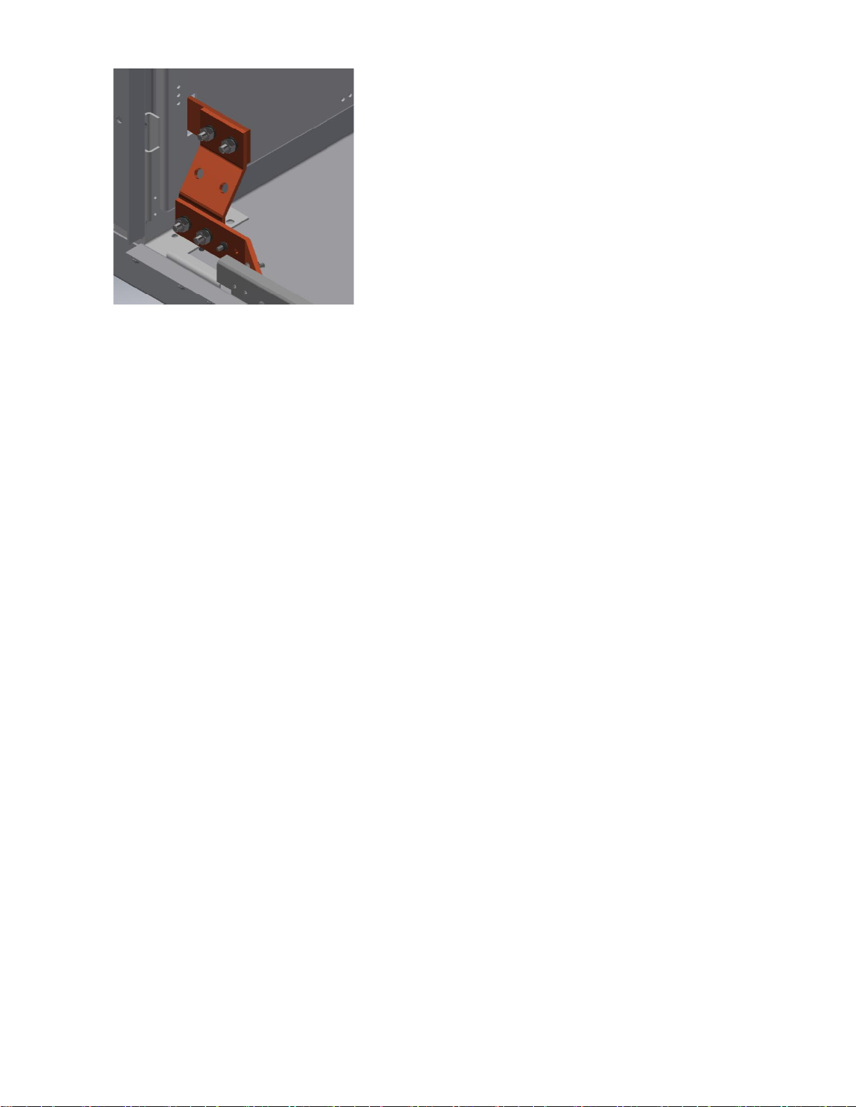
It should be reconnected to the vertical stub it
was removed from, and to the equivalent
vertical stub in the section to the left of the
shipping split with the hardware provided.
Tighten the nuts 19.4lbs ft [26.3 Nm].
Consult the schematic diagram(s) and
reconnect all LV wires at the interconnection
terminal blocks or plugs and sockets provided
at the split, and all the MV power cables.
5.2.7 On Arc-resistant IEC sections the
additional parts used to create the arc shroud
(that guides arc products exiting from the top of
the system upwards) may be shipped
separately, the instructions given in Annex 2
should be followed to assemble it on site. The
shroud for each section consists of 4 parts plus
all the fixing screws required. If rear access to
the System is not possible, the rear and side
pieces of the shroud should be assembled to
the enclosure before the System is placed in its
final position.
When complete, the shroud should form a wall
around the top of the Converter System.
Partitions between parts of the shroud above
different sections have large opening in them to
give arc products the maximum amount of
space to expand into. It is important that all
fasteners between parts of the shroud, and
between shroud parts and the enclosure top are
in place and securely tightened.
5.3 Cabling
ACCESS TO THE CABLE TERMINATIONS
SHOULD ONLY BE MADE WHEN THE
POWER FEEDS ARE ALL TURNED OFF,
LOCKED OFF AND PREFERABLY EARTHED
/ GROUNDED.
5.3.1 Incoming MV cable terminals are mounted
in the Controller section, or DOL section, and
provide easy termination of incoming power
wiring. Space is provided for the spreading,
bending, and termination of over-size cables if
these are needed to minimize voltage drops.
Follow instruction provided by the cable or
cable termination manufacturer.
The DOL and Controller doors are
locked/bolted closed, and the Controller door
cannot be opened if the Disconnector is not
open.
The incoming power cable gland plate is
mounted on the base, or roof, in line with the
cable terminations.
5.3.2 Outgoing MV cable terminals are mounted
in the Converter and/or Load Switching section,
and any Stepper sections, and provide for easy
termination of power wiring from the Converter
System to the Heater(s). Plenty of space is
provided for cable bending, and termination.
Follow instruction provided by the cable or
cable termination manufacturer.
The Converter, Load switching, and Stepper
Sections are key locked, and the Converter
door is blocked closed if the Disconnector is
closed.
The outgoing power cable gland plate is
mounted on the base, or roof, in line with the
cable terminations.
5.3.3 Incoming and outgoing LV cable terminals
are mounted in the LV compartment on the
Converter front door. The main control board
and all Temperature and Over-temperature
controls are also located in the LV
compartment. This compartment is segregated
from High Voltage and can be opened without
de-energizing the main power if local codes
permit. All required PPE should be worn.
The LV compartment door is key locked.
An LV cable gland plate is mounted on the
base, or roof, to the right of the power cable
gland plate.
__________________________________________________________________________

10

C: COMMISSIONING
6...Commissioning
Precautions & Warnings
READ AND UNDERSTAND
SECTION A ABOVE BEFORE
CARRYING OUT THE WORK
DETAILED BELOW
6.1 Before Powering Up
Chromalox takes great pride in knowing that we
have provided to you a product of premium
quality and workmanship. We have taken every
precaution to ensure that your equipment
arrives safe and secure.
However, shock, vibration and temperature
changes during shipping can cause some
components to become loose.
Wiring and Connections:
Since electrical wiring and mechanical
connections may be loosened during shipment,
before first energizing the Converter System,
inspect wiring for damage and repair or replace
if needed.
Inspect for loose electrical and mechanical
connections. Tighten or replace defective
crimp-style lugs. Re-solder loose solder
connections. Tighten or replace all loose or
missing hardware –see page 17 for fastener
torque values.
6.2 Electrical Testing
Check that Supply Line cable connections to
the Converter System match phasing rules for
the site.
Disconnect Lightening Arresters if fitted.
Remove all fuses from VTs and CPTs. Label
these so that they can be correctly placed back
into service.
Close the Disconnector.
Simulate a closed Contactor by shorting each of
the Contactor Vacuum Interrupters (VI) using a
slim wire connected between the terminals at
each end of each VI.
Carry out Power Frequency (Hi-pot) tests to
ensure that there is no hidden damage in the
insulation system as follows:
Perform a phase to phase Power Frequency
(Hi-pot) test, across the Supply Line terminals.
Perform a phase to earth / ground Power
Frequency (Hi-pot) test, from each Supply Line
terminal to the enclosure.
Perform a phase to phase Power Frequency
(Hi-pot) test, across the Load terminals.
Perform a phase to earth / ground Power
Frequency (Hi-pot) test, from each Load
terminal to the enclosure.
System Max
Voltage kVac
Factory Test
Voltage kVac
Site Test
Voltage kVac
7.2
20
16
The voltage should be raised gradually to the
Site Test voltage, then kept at that voltage for 1
minute, then reduced gradually to zero.
Remove the wires connected between the
terminals at each end of the contactor VIs.
Replace all fuses in VTs and CPTs.
.
__________________________________________________________________________

D: OPERATION
7...Startup and Operation
Precautions & Warnings
READ AND UNDERSTAND
SECTION A ABOVE BEFORE
CARRYING OUT THE WORK
DETAILED BELOW
7.1 Theory of Operation
The controls system uses a PLC to
automatically control the Heater output to meet
the 0-100% process demand signal (generated
internally or customer supplied). There are 2
control methods: Full SCR, and SCR w/Trim.
In a full SCR system, the power output to the
heaters is controlled using solid state SCRs
(Silicon Controlled Rectifiers). If the process
demand signal is at 50% (12 mA demand), the
SCRs would be “gated” into conduction to allow
50% of the available power to be sent to the
heater. Full SCR systems with multiple heater
circuits all operate at the same demand level,
they are not staged. For example, a 3 SCR
system with a process demand of 45% will
trigger all 3 SCR’s at 45%.
In an SCR w/Trim system, the first load utilizes
an SCR, while all remaining loads are
controlled by a contactor. The PLC looks at the
process demand and calculates how many
contactor loads need energized, and what the
final SCR output will need to be. Some stepper
systems may use different sized loads.
In either mode, this power proportioning is
controlled by one of two methods: Zero
Crossover, or Phase Angle.
Zero Crossover Control
Zero Crossover control (ZC) proportions the
amount of power to the load by supplying full
sine waves of power to the load for a short
period, then supplying no power for a short
period, this sequence repeating. The ratio of on
to off periods determines the average power to
the load. This is accomplished by gating the
SCR switches into conduction at the zero volt
point on the sine wave, resulting in much lower
harmonic distortion & EMI. The ZC control is
based on a 1 second time base so in the 50%
demand example, the SCR switches would be
conducting full Sine of power for ½ second and
no power for ½ second resulting in 50% of the
available power being delivered to the load.
This is the control mode used in normal
operation of the Heater.
Phase Angle Control
Phase Angle control (PA) gates the SCRs into
conduction at various angles of the incoming
sine wave. Given a 50% demand, the SCR
switches would be gated into conduction at 90
degrees in the positive sine wave, and again in
the negative sine wave. This type of control is
very precise but can cause harmonic distortion
issues, so it is restricted to use in the Dryout
Mode only unless manually selected by the
operator. When PA is manually selected, the
main HMI screen will flash an indicator to alert
that PA is active.
Slow Start Mode
In Slow Start mode (SS), zero crossover is
used to start up to gradually increase the power
over a 100 second interval, until either 100%
output is achieved, or the ramping output
reference equals the power demand. This
mode is selectable.
Dry-out Mode
The Dry-out Mode (DM) feature, is used to “dry
out” Heaters that may have accumulated
moisture during long periods without power
applied. Phase Angle firing mode is used to
limit the voltage applied to the elements. This
is required in HV heating systems due to the
large amount of energy that can be delivered in
a single burst. As a Heater that contains
significant moisture could be damaged by full
voltage, DM helps to minimize this risk.
Note that in SCR w/Trim systems, the
Converter is used to dry-out the heater attached
to the Stepper before it is connected to the
supply line power.
Dry-out can be accomplished in two ways:

13
Manual: If Manual Dry-out is selected from the
HMI, the system will dry out the selected Heater
until it is turned off from the HMI.
Automatic: The Automatic Dry-out mode utilizes
feedback from the residual current monitoring
system, comparing the residual current with a
preset value from the HMI. If this preset is
exceeded, the controller will enter automatic
dry-out mode and stay in that mode for the
number of minutes set on the HMI.
If the system is unable to dry-out a Heater after
the programmed number of attempts, the
affected Heater will be disabled, and the HMI
will display a dry-out fault condition.
In both dry-out modes, the maximum output is
set using the HMI, up to a maximum of 20%. If
the process demand signal is lower than the
Max setting on the HMI, the lower of the two
signals will be used to avoid damaging the
process.
7.2 Electrical Interlocks
There are seven basic electrical interlocks that
will disable the Converter output:
Sheath or Flange Temperature Over-temp
(OTC). The System can be equipped with
multiple Over-temp Limit Controllers to protect
the heater from failure. The OTC(s) indicate
both an ALARM and a TRIP condition on the
HMI. The ALARM condition is a warning and
will self-reset when the temperature falls to a
safe value. The TRIP condition must be
manually reset (via HMI or remote input), after
the temperature has lowered back to a safe
value.
Residual leakage current. If the leakage current
exceeds the trip point set on the relay, the relay
will signal the PLC to trip the MV Contactor to
disable the affected load. The relay must be
manually reset (via HMI or remote input), and
the alarm condition cleared before the heater
can be re-enabled.
The disconnector switch auxiliary contact must
show that the disconnector switch is closed for
each load before the heater can be energized.
The Blown Fuse Auxiliary contact must show
that the MV fuses are all intact before the
heater can be energized.
The local and external E-Stop circuits must be
made before starting.
Any remote permissive inputs must be
energized.
Each SCR is controlled by a firing card that has
an alarm contact that must be clear, indicating
the SCR is not overheating.
7.3 HMI Screens - General
The HMI screens have a navigation bar across
the bottom. This menu stays visible for most
screens making navigation between screens
easy, the leakage current screen being the only
exception.
When the Converter System is first energized, it
is important to set up the HMI using the SETUP
screen before using any of the control screens.
The following sections show screens that are
used in normal operation only. See ‘Annex A’
for more detailed explanations, and for
additional set-up, dry-out, and diagnostic
screens.
14
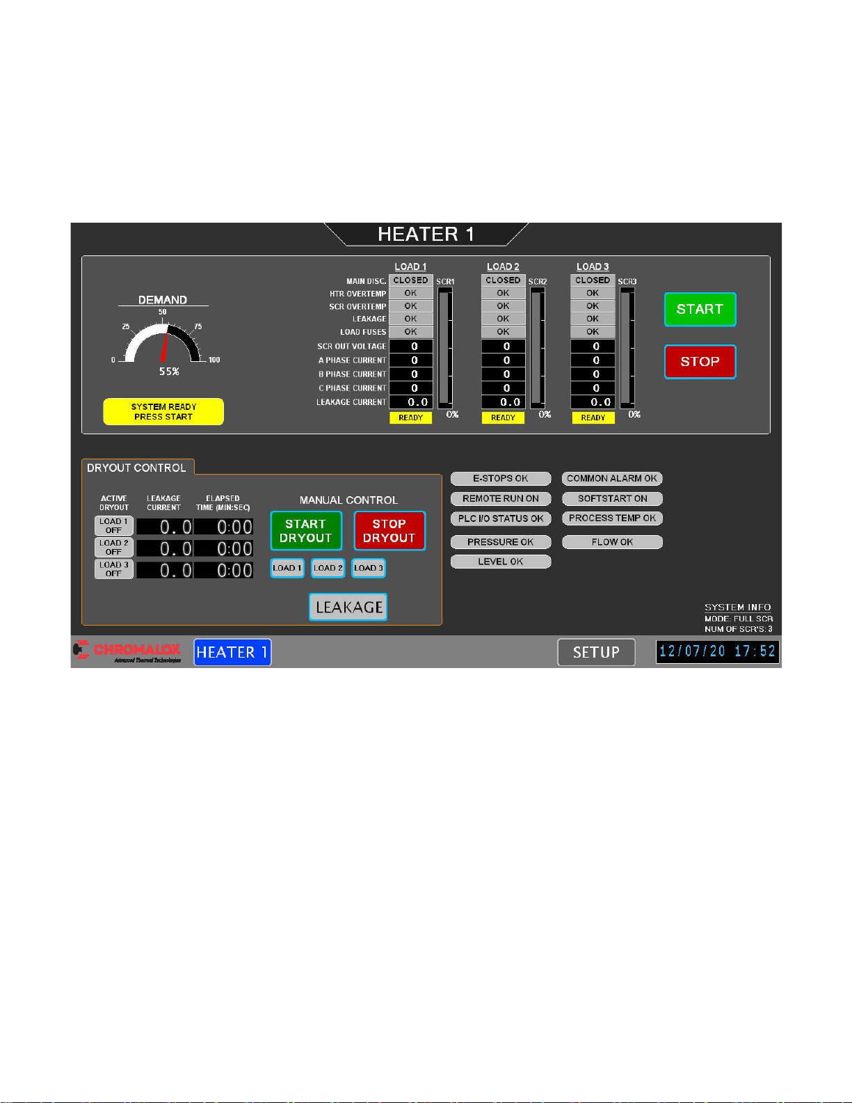
7.4 HMI Screens
The HEATER screen shows an overall view of the system, displaying system demand, permissive
signals, measured output voltages, phase currents, leakage currents, and status for each heater load.
This screen also displays DRYOUT control, as well as START/STOP functionality. The following shows
an example of a 3 SCR system in AUTO mode, with the demand coming from a temperature controller or
remote demand signal. The system is shown READY, pressing the START button would energize the
heater. System permissive signals and indications (E-stop, Common Alarm, etc..) are shown on the
bottom right. Some indications (Pressure, Flow, etc.) may not apply to all systems.
15
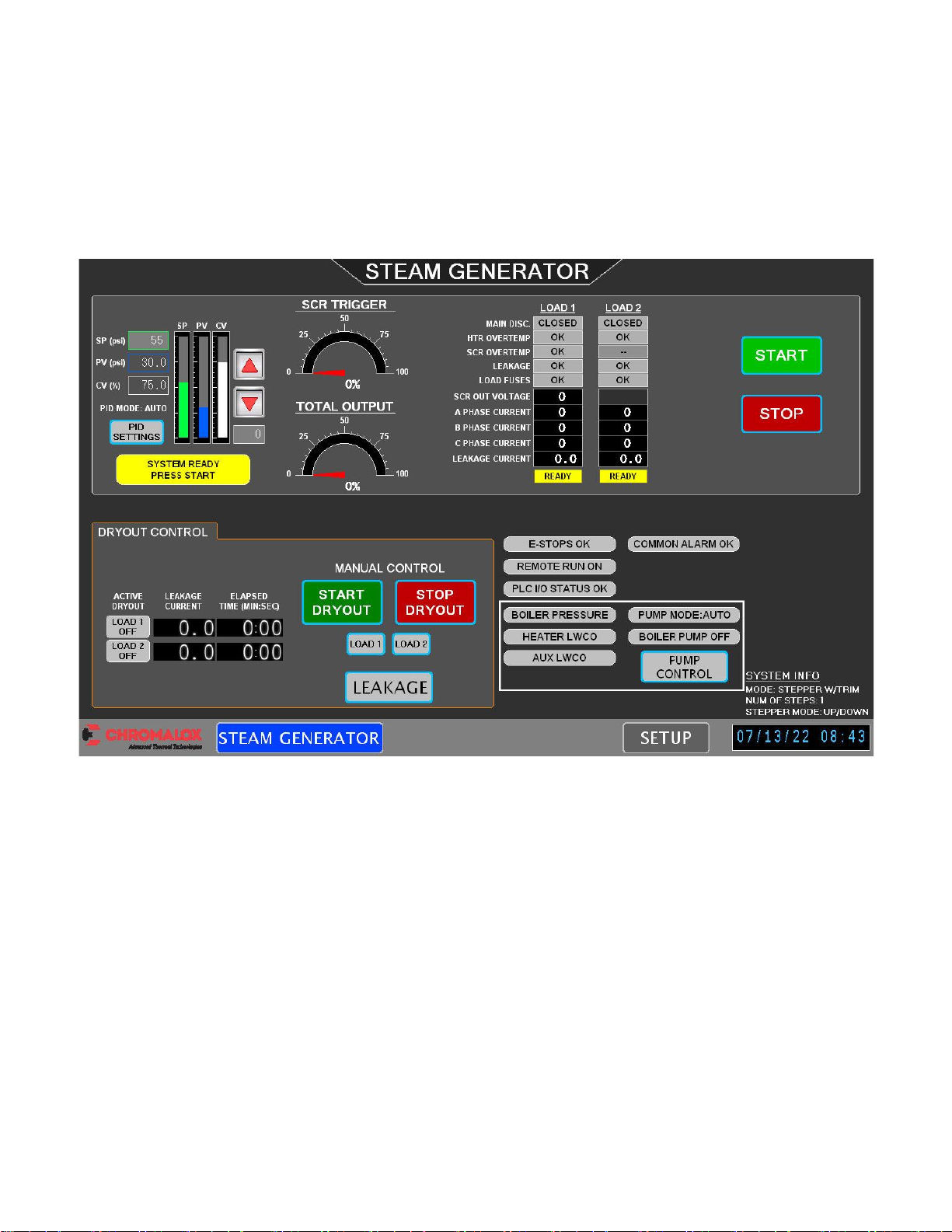
7.5 HMI Screens (Steam Generator Systems)
The STEAM GENERATOR screen shows an overall view of the system, displaying system demand,
permissive signals, measured output voltages, phase currents, leakage currents, and status for each
heater load. This screen also displays DRYOUT control, as well as START/STOP functionality. The
following shows an example of a 2 circuit Stepper system with an internal PID loop in AUTO mode. The
system is shown READY, pressing the START button would energize the heater. System permissive
signals and indications (E-stop, Common Alarm, etc..) are shown on the bottom right. Steam Generator
specific signals are shown in the white border (Pressure status, Pump Status, Low Water Cutoff).
____________________________________________________________________________
16
E: INSPECTION and MAINTENANCE
8...Inspection & Maintenance
Precautions & Warnings
READ AND UNDERSTAND
SECTION A ABOVE BEFORE
CARRYING OUT THE WORK
DETAILED BELOW
8.1 Monitoring
Any one of the following will prevent the
Converter starting:
•MV Disconnector open
•Emergency Stop engaged
•Remote Run off
If any of the following goes into a fault condition
the MV Contactor will be turned off.
•MV Fuses
•Over-temp monitors
•Ground / Earth Fault monitors
•Firing Circuit
Determine and rectify the cause of the fault
before making any attempt to re-energize the
Converter System.
8.2 Preventive Maintenance
Preventive maintenance consists of
inspections, tests and cleaning of equipment at
scheduled intervals. It helps detect and correct
conditions that could cause equipment
malfunction. The scheduled maintenance
instructions in this manual are intended to
enhance and form part of the site’s planned
maintenance program.
Preventive Maintenance Schedule
The schedule for conducting preventive
maintenance depends usage and site
conditions.
Unless the site has a known environmental risk,
it is recommended that maintenance be carried
out annually until experience allows the
schedule to be adjusted.
If the site has a known environmental risk, it is
recommended that maintenance be carried out
every six months until experience allows the
schedule to be adjusted.
It is recommended that the maintenance
interval should never exceed 5 years.
Enclosure Exterior
Inspect the Converter System’s exterior:
a. Inspect fan air inlet and air exhaust filters
and replace if necessary.
b. Touch up all chipped paint with primer and
paint. Remove any corrosion with sandpaper.
Enclosure Interior
Before accessing the interior of the System, it is
important to remove any materials from the
outside surface that may enter the System.
a. Wipe off all dust, and moisture from the
exterior surface of the door and surrounding
enclosure frame with a lint-free cloth.
b. Remove oil, and grease from the exterior
surface of the door and surrounding
enclosure frame with an alcohol-free
cleaner.
Clean and inspect the System interior:
a. Remove loose dust and dirt with a vacuum
cleaner.
b. Wipe off all moisture, and all remaining
dust, and dirt with a lint-free cloth.
c. Remove any sticky residues with a dry, lint-
free rag, using an alcohol-free cleaning
solvent.
d. Inspect for evidence of dripping water or
liquids falling on equipment parts. If found,
determine the cause and correct.
e. Inspect for rust on metal parts. Repair or
replace if found.
f. Inspect for signs of insect or animal
damage. Remove any spider’s webs.
g. Inspect for signs of mold.
h. Inspect for hydrogen sulfide corrosion (black
marks on plating) on conductive parts and
electrical contacts. Repair or replace if
found.
j. Inspect for salt corrosion on metal parts and
electrical contacts. Repair or replace if
found.
k. Inspect for partial discharge erosion on
insulators (signs of tracking on insulating
surfaces). Determine the cause of the

17
discharge, and repair or replace if found.
Replace insulators that have been
compromised by tracking.
l. Inspect for signs of overheating. If found,
determine the cause and correct. Repair or
Replace damage parts.
m. Inspect for worn or broken parts. If found,
determine if there is an underlying cause,
the repair or replace.
n. Inspect door gaskets and replace if worn
and/or deteriorated. Repair or replace if
found.
p. Make sure that moving parts move freely
and do not stick. Lubricate if necessary.
r. Inspect for signs of foundation damage or
movement.
Lubrication
Oil door hinges and latches with light machine
oil.
The Disconnector mechanism moving parts
should be lubricated every five years with
ISOFLEX TOPAS NB 52.
If necessary, Disconnector contact knifes
should be lubricated with ISOFLEX TOPAS
NCA 52.
The Contactor should not be lubricated.
Exercise Mechanisms
After lubrication, exercise the hinges, latches
and Disconnector mechanism to ensure free
movement. Close the Controller door to
exercise the Disconnector mechanism.
8.3 Wiring and Connections
Check wiring and connections:
a. Inspect wiring for wear, fraying, damage,
and evidence of overheating. Replace if
needed.
b. Inspect for loose electrical and mechanical
connections.
Replace damaged lugs.
Re-solder loose solder connections.
Replace all loose or missing hardware.
Tighten all connections. Special care
should be taken to ensure that all power
and earth / ground connections are fully
tight –see page 17 for fastener torque
values.
8.4 Contactors
Vacuum Contactor are sealed units and require
very little maintenance. Refer to contactor
manufacturer manual included in the document
package for maintenance instructions.
8.5 Converter SCR Stacks
SCR Stacks and associated electronics boards
and wiring harnesses are designed for long
trouble-free operation. Refer to Chromalox for
maintenance instructions.
8.3 Fault and abnormal Conditions
Indications
MV Fuse Blown
If any of the main MV power fuses open, the
blown fuse trip bar will open one or more micro-
switches. The CONTROL screen (see above)
gives a fuse open alarm. Following all safety
precautions detailed above; determine the
cause of the blown fuse and replace.
When removing a fuse, rotate the fuse body
slightly to help ease the fuse ferrule out of the
fuse clip. If necessary, lubricate the fuse clips
with Mobil® 28 red grease as the fuse is
rotated. Coat replacement fuses with this
grease to ease future removal.
Over-temp Fault
If any of the Over-temperature controllers trip, it
will be indicated in red as “OTC TRIP”. Run
mode can only be activated after the
overtemperature is cleared and reset.
Residual Current Fault
A residual current monitoring relay monitors
leakage current and sends the measured value
to the PLC. If the leakage current is above the
preset limit, the residual current relay will
energize, and the affected load will shut off. The
CONTROL screen will indicate a fault condition.
Firing Card
If an SCR heatsink overtemp is detected the
CONTROL screen will indicate the fault
condition.
Contactor Fault
If a Contactor is energized but no status is
received, a timer will begin. If this timer

18
completes, the system will stop, and the HMI
will indicate the fault.
Contactor Welded
If a Contactor is released but the status
remains, a timer will begin. If this timer
completes, the system will stop, and the HMI
will indicate the fault.
8.7 Testing
Conduct Power-Frequency (Hi-pot) tests to
clause 6.2.
8.4 Renewal Parts
See spares list supplied separately.
________________________________________________________________________
FASTENER TORQUES
All Torques +/- 10%
M5 Torx Head Thread Rolling Screws 19 lbs-in [2.1Nm]
M5 Stainless Steel Screws 19 lbs-in [2.1Nm]
M5 Nuts for Securing Steelwork 56 lbs in [6.3 Nm]
M6 Hex Nuts for Securing Ground Bars 52 lbs-in [5.8 Nm]
M6 Truss Head Stainless Steel Screws 71 lbs-in [8.0 Nm]
M6 Hex Head Bolts for Securing Gland Plates 95 lbs-in [10.7 Nm]
M6 Pan Head Screws for Securing Door Lock Guides 95 lbs in [10.7 Nm]
M6 Nuts for Securing Steelwork 95 lbs in [10.7 Nm]
M8 Hex Nuts for Securing Contactor Cable Lugs & Copperwork Joints 9.4ft lbs [12.7Nm]
M8 Hex Head Bolts for Securing the VTs, CPT, Contactor & Lifting Angles 19.2 lbs-ft [26 Nm]
M10 Hex Nuts for Securing Inductor and SCR Cable Lugs & Fuse Copperwork 19.4 lbs ft [26.3Nm]
M10 Hex Head Nuts for Securing Ground Bars 19.4 lbs-ft [26.3 Nm]
M10 Hex Head Bolts for Securing the Moldings to the Sub-Panels 38 lbs-ft [52 Nm]
M12 Hex Head Bolts for Securing the Disconnector 66 lbs-ft [90 Nm]
19
ANNEX 1: HMI SCREENS
The following pages give a full description of all the screens available on the HMI for full SCR systems.
Note that actual layout may vary slightly.
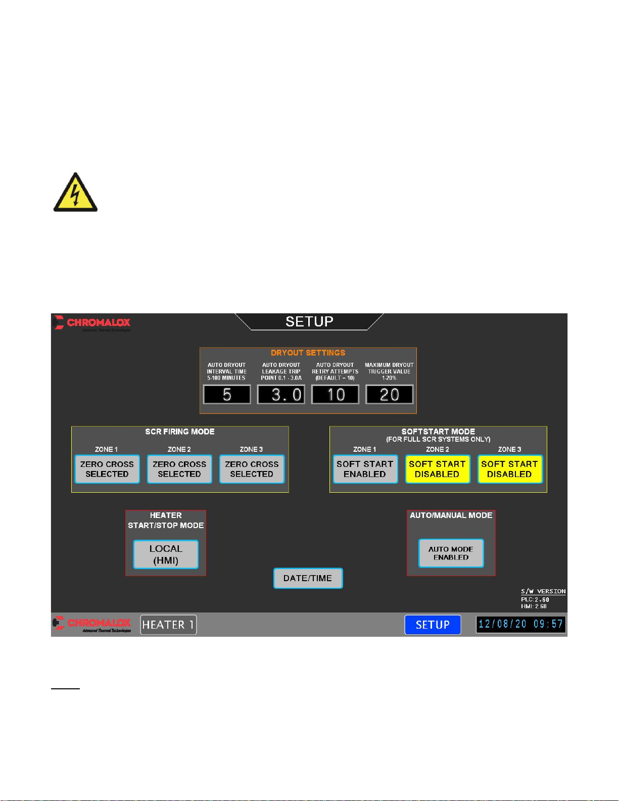
A1.1 Set-Up Screen
NOTE: The Low Voltage Section should be checked and verified, and the following settings
should be set before energizing the High Voltage
Energize the Low Voltage Supply.
Touch (SETUP)
The SETUP screen is used to configure dry-out settings, select between Auto/Manual mode, enable
Phase Angle or Zero Cross firing, toggle local/remote mode, and update the Date/Time.
Full SCR System
Notes:
“AUTO DRYOUT INTERVAL TIME”: This configures how long an Auto-Dryout cycle will run. This is
selected in minutes.
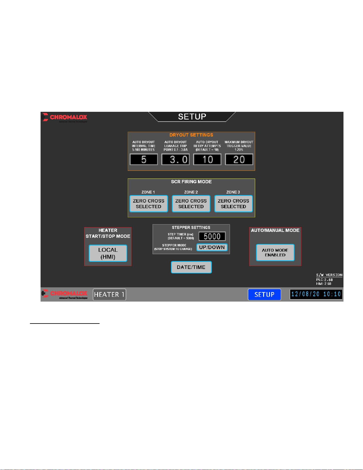
20
“AUTO DRYOUT LEAKAGE TRIP POINT”: This is the amount of leakage current (Amps) that will
trigger and Auto-Dryout sequence. The maximum allowed is 3.0A.
“AUTO DRYOUT RETRY ATTEMPTS”:If the number of dry-out attempts for an element reaches
this number and the element is still not dry, dry-out will be disabled for this load, preventing any
further dry-out cycles, and a ‘Dry-out Fault’will be indicated on the HMI.
“MAXIMUM DRYOUT TRIGGER VALUE”: The maximum dry-out trigger % is restricted to a
maximum of 20% of full load current to avoid heater damage and to limit harmonics caused by Phase
Angle firing.
SCR Stepper System
Stepper w/Trim Settings:
“STEP TIMER (ms)”: This adjusts the time between steps when the system is turning on to meet the
initial demand. Once the demand is met, this time is automatically reduced to allow quicker tracking
of the demand signal.
“STEPPER MODE”: Two modes exist in stepper systems: Up/Down and Circular. These modes
determine which loads are stepped on/off as demand goes up/down.
In Up/Down mode, the first load will always be the first to turn on and last to turn off.
In Circular mode the system tracks the loads to help spread out the time that each load is energized.
If load 3 is the first load energized, it will be the first load to turn off. Note: Circular mode is not
available in Progressive Stepper systems.
Other manuals for DirectConnect
1
Table of contents


