Church Organ World Makin User manual

Sovereign House
30 Manchester Road, Shaw
Lancashire OL2 7DE
01706 888 100
www.churchorganworld.co.uk
Showrooms at Shaw Lancashire and Mixbury Oxfordshire
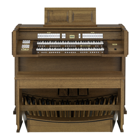
Makin Organ Owners Manual

Issue 5.6PW 19/05/2013 Church Organ World - Makin User Manual Page 1 of 34
1. Introduction
Congratulations on your decision to purchase a new Church Organ World organ. Church Organ World
appreciates your patronage and welcomes you to our family of customers. You have now become the owner
of a truly exceptional instrument.
Church Organ World produce many instruments, both standard and custom which makes it difcult to
create a manual that exactly ts each specic instrument. To enable you to get to know all of the particular
functions of your instrument this manual describes all the standard functions available on Church Organ
World - Makin organs.
Church Organ World instruments are continually being developed as a result of ongoing research and dialogue
with our Customers. While we try to keep the manual up to date you may nd a function on your organ
that is not in the manual or is different from the manual. It is also possible that your instrument may have
additional functions that do not appear in the manual because you, the client, have specially commissioned
the additional requirements. Should information you require not be in the manual, you can always contact
us so that we may supplement the information you have.
This owner’s manual contains all kinds of useful information that will allow you to explore the instrument,
and put it into use. We, the builders of this instrument, would be pleased to help you explore its properties.

Issue 5.6PW 19/05/2013 Church Organ World - Makin User Manual Page 2 of 34
1. Contents
1. Introduction ......................................................................................... 1
2. An Overview ......................................................................................... 5
.. Type of Wood.....................................................................................................................
.. The Organ Bench ..............................................................................................................
.. The Keyboards...................................................................................................................
... Synthetic keyboards ....................................................................................................................................
... Wooden keyboards......................................................................................................................................
.. The Pedalboard..................................................................................................................
.. The Music Desk.................................................................................................................
... Horizontally and Vertically Adjustable Music Desk...............................................................................
... Horizontally Adjustable Music Desk ........................................................................................................
.. The Roll-Top Cover ..........................................................................................................
.. Construction Standards....................................................................................................
.. Available Space and Symmetry........................................................................................
.. Stops ....................................................................................................................................
... Lighted rocker tabs......................................................................................................................................
... Drawstops.....................................................................................................................................................
.. Position of Accessories ...................................................................................................
.. Thumb Pistons.................................................................................................................
.. Toe Pistons .......................................................................................................................
... Coupler Toe Pistons ................................................................................................................................
... Capture Toe Pistons ................................................................................................................................
... Special Toe Pistons..................................................................................................................................
.. Expression Pedals ............................................................................................................
3. The Organ Sound ...............................................................................11
.. Intonation.........................................................................................................................
.. Choice of Temperament .................................................................................................
4. Set Up.................................................................................................. 12
.. Connecting the Organ....................................................................................................
.. Fitting the Pedalboard ....................................................................................................
.. Switching On....................................................................................................................
.. Pedalboard Lighting........................................................................................................
5. Functions ............................................................................................13
.. The Thumb Piston .......................................................................................................
.. Numbered Pistons...........................................................................................................
.. Menu .................................................................................................................................
.. + and -...............................................................................................................................
.. English (ENG) English Intonation................................................................................
.. French (FRE) French Intonation...................................................................................
.. Baroque (BAR) Baroque intonation. ............................................................................
.. Manual Bass (MB)...........................................................................................................
.. Transposer (TRANS) ......................................................................................................
.. SET ....................................................................................................................................

Issue 5.6PW 19/05/2013 Church Organ World - Makin User Manual Page 3 of 34
.. MIDI .................................................................................................................................
.. Volume (VOL) .................................................................................................................
.. Tremulants........................................................................................................................
.. Couplers............................................................................................................................
.. Manual Couplers .............................................................................................................
.. Pedal Couplers.................................................................................................................
.. Sub and Super Couplers .................................................................................................
.. Liquid Crystal Display (LCD)........................................................................................
.. Memory Lock...................................................................................................................
.. Acoustics (Reverberation)..............................................................................................
... Rotary Reverberation Controls .............................................................................................................
... Thumb piston reverberation controls...................................................................................................
.. Audio & MIDI External Connections ..........................................................................
6. The Menu System................................................................................19
.. Programmable MIDI ......................................................................................................
.. Tuning Mode....................................................................................................................
.. Temperaments .................................................................................................................
.. Keyboard Mode ...............................................................................................................
.. Reset Procedures .............................................................................................................
.. Data Dump Mode ...........................................................................................................
.. Standard Intonation ........................................................................................................
.. Reverb ...............................................................................................................................
... For instruments fitted with length and Volume setting knobs ...........................................................
... For instruments with Menu setting ........................................................................................................
.. Key Volumes ....................................................................................................................
.. Sound Reproduction System .........................................................................................
7. Using the Capture System...................................................................26
.. Capture Combinations ...................................................................................................
.. Setting the Capture Combinations................................................................................
.. Recalling Capture Combinations ..................................................................................
8. MIDI system .......................................................................................27
.. What is MIDI? .................................................................................................................
.. MIDI Terminology..........................................................................................................
.. Components Relevant to MIDI:....................................................................................
.. Working with MIDI ........................................................................................................
.. MIDI Channels................................................................................................................
.. MIDI Controllers ............................................................................................................
... Control Changes Transmitted .................................................................................................................
... Control Changes Received .......................................................................................................................
... System Exclusive Messages.......................................................................................................................
.. How and What To Connect?..........................................................................................
.. Programmable MIDI ......................................................................................................
.. Connecting to an Expander...........................................................................................
.. Connecting a Computer via a USB Port ......................................................................
9. Maintenance .......................................................................................32

Issue 5.6PW 19/05/2013 Church Organ World - Makin User Manual Page 4 of 34
.. The Console .....................................................................................................................
.. Pipes ..................................................................................................................................
.. Pedalboard Lights............................................................................................................
.. Resetting to Factory Defaults.........................................................................................
10. Miscellaneous Advice ......................................................................... 33
.. Pedalboard........................................................................................................................
.. Organ Bench ....................................................................................................................
11. Information ........................................................................................34

Issue 5.6PW 19/05/2013 Church Organ World - Makin User Manual Page 5 of 34
2. An Overview
2.1. Type of Wood
A Makin instrument is nished partly with veneer and partly with solid wood. Medium or light oak nishes
are standard but your instrument may have another colour or be another type of wood.
2.2. The Organ Bench
Your organ is provided with a bench that contains a music shelf or box. If you wish, you can order an
adjustable height bench. The bench is supplied in the same type of wood as the cabinet.
2.3. The Keyboards
2.3.1. Synthetic keyboards
Standard keyboards are nished with synthetic key surfaces. Keyboards are designed with a
mechanical toggle touch system to attain a church organ feel.
2.3.2. Wooden keyboards
Depending on your choice, your instrument may be tted with wooden keyboards. Keyboards are
equipped with a patented magnetic toggle system to attain a church organ feel.
2.4. The Pedalboard
The pedalboard is removable. At the front of each pedal key is a magnet. This magnet normally sits in
close proximity to a reed switch, which is invisibly mounted behind the front panel at the bottom of the
console. When you depress a pedal key, the reed switch is activated by the magnet at the end of the key.
2.5. The Music Desk
2.5.1. Horizontally and Vertically Adjustable Music Desk
This music desk can be horizontally adjusted by pulling it towards you or pushing it away. In either
case the music desk is automatically stopped at its limit of travel. When pushing the music desk
forwards or backwards, care should be taken that the music desk is moved equally on both sides.
This will prevent the music desk from skewing, which may jam it. The music desk can be vertically
adjusted by tweaking the grips left and right behind the music desk simultaneously and moving the
music desk up or down. After the music desk has been adjusted to the right height, it can be locked
by rst releasing the grips and only then the music desk itself. In either case the music desk is
automatically stopped at its limit of travel. When moving the music desk vertically, care should be
taken that the music desk is moved up and down on both sides at the same time. This will prevent the
music desk from slanting, which may jam it. The adjustable music desk may need to be repositioned to
allow the roll top cover or the top lid of the instrument to be closed.
2.5.2. Horizontally Adjustable Music Desk
This music desk can be horizontally adjusted by pulling it towards you or pushing it away. In either
case the music desk is automatically stopped at its limit of travel. When pushing the music desk
forwards or backwards, care should be taken that the music desk is moved equally on both sides . This
will prevent the music desk from skewing, which may jam it. The adjustable music desk may need to
be repositioned to allow the roll top cover or the top lid of the instrument to be closed.

Issue 5.6PW 19/05/2013 Church Organ World - Makin User Manual Page 6 of 34
2.6. The Roll-Top Cover
Makin models may be tted with a lockable wooden roll top cover with a lock. The roll top cover
lock is located on top of the instrument, behind the music desk. The lock comes with a key.
Warning
You can lock the cover without using the key but the key is necessary to open the organ.
Therefore, always take care that the key is not left within the console before closing the
cover.
Open the instrument as follows:
1. Insert the key in the roll top cover lock.
2. Turn the key a quarter of a turn to the left; this brings the lock up.
3. Push the roll top cover up.
Close the instrument as follows:
1. Make certain that the key is not in the lockable space (see warning).
2. Check that if there is an adjustable music desk it is positioned so that it will not foul the closing
cover.
3. Pull the roll top cover towards you.
4. Push the roll top into the locked position.
2.7. Construction Standards
When building your instrument, the accepted standards in organ building are taken into account. The most
important standards are:
•
The American Guild of Organists (AGO) Standard 2002 is mainly used in the USA. The most striking
characteristic of AGO instruments is the design of the pedalboard. The AGO pedalboards have a concave
pedal layout whose keys splay out to the front (radial) with a concave and splay radii of 8ft 6in
• The Bund Deutscher Orgelbaumeister (BDO) Standard 2000 is mainly used for instruments built for
mainland Europe. The BDO standard allows for straight 30 key or radiating 32 key concave pedal boards
where the concave radius is 3680 mm (12ft 1in) and 3350 mm (11ft) splay radius.
•
The Incorporated Society of Organ Builders (ISOB) Standard 1967 for British organ builders. Similar
to the AGO standard with a few differences. The most signicant is the requirement to align middle D
on the lower keyboard with the Pedalboard middle D and the use of 8ft 6in for concave and splay radii.
• The Royal College of Organists (RCO) specication 1904. It is often quoted as a standard but in fact
the specication was for a single instrument built for the RCO Lecture Hall by Norman and Beard. It is
notable for having a pedalboard concave radius of 12ft 6in and a splay radius of 8ft 6in.
Many pipe organs were built before any standard existed, other than those imposed by the builders, and it is
therefore not uncommon to nd organs that do not comply fully with any standards. It is not unknown for
instruments, in the UK where the European continental inuence has always been very strong, to be built
utilizing part of any of these standards . The standard adopted for your Makin organ will depend on the
model you have chosen. The order of stops will be, as much as possible, in accordance with the standards
applicable to your instrument.

Issue 5.6PW 19/05/2013 Church Organ World - Makin User Manual Page 7 of 34
2.8. Available Space and Symmetry
The available space is especially important. Stops and Pistons have to be far enough apart to allow for ease
of operation. A good symmetry has to be achieved between the left and right stop jambs for draw stops. On
instruments with tab stops these are generally located above the manuals in accordance with the appropriate
layout standard. Every attempt has been made to make the overall nish aesthetically pleasing. The following
illustrations show typical layouts for Makin instruments.
Illustration of a Typical Tab Stop Instrument
Music Desk
(Shown detached)
Roll Cover
Lock
Thumb Pistons
ENG, FRE, BAR
Swell
Tab Stops
Great
Tab Stops LCD
Display
Swell Division
Capture Pistons
Thumb
Piston
Sw to Ped
Pedal
Tab Stops
General
Capture
Thumb
Pistons
Reverb
Controls
& Memory
Lock
Thumb Piston
Set
MIDI Thumb
Pistons
Thumb Pistons
Sw to Gt,
Gt to Ped
Great Division
Capture Pistons
Toe Pistons
Capture 1 - 3
& Sw to Gt
32 Key Concave
Radiating
Pedalboard
Swell
Expression
Pedal
Toe Pistons
Capture 3 - 6
& Gt to Ped
Speaker
Switch
On/Off
Switch
0 Thumb
Piston
Menu Thumb
Piston
Thumb
Pistons
- and +
Thumb Pistons
VOL, TR, MB

Issue 5.6PW 19/05/2013 Church Organ World - Makin User Manual Page 8 of 34
Illustration Of A Typical ree Manual Draw Stop Instrument
The Music Desk has been omitted to show the controls that it would normally cover. The keyboard pistons
have a similar arrangement to the two manual illustration with couplers, general capture divisional capture,
SET and 0 pistons occupying similar positions on the keyboard frontal.
32 Key Concave
Radiating Pedalboard
Expression Pedals
Thumb Pistons
-, +, MENU
Toe
Pistons On/Off
Switch
Roll Cover
Lock
LCD Display
Reverb
Controls
Thumb Pistons
VOL, TR
4 x MIDI
MB
Memory
Lock
Pedal Draw
Stops
Swell Draw
stops
Choir Draw Stops
Great Draw Stops

Issue 5.6PW 19/05/2013 Church Organ World - Makin User Manual Page 9 of 34
1.1. Stops
Depending on the model, the instrument will be tted with one of the types of stops mentioned below:
1.1.1. Lighted rocker tabs
The speaking stops and accessories are designed as lighted rocker tabs. After activating or deactivating
a stop, a lighted rocker tab springs back to the central position. Each stop has a lamp which lights up as
soon as the stop is activated. The rocker tab has a push for on, push for off action and can be activated
by pushing at the top or bottom of the tab. On AGO instruments tab stops appear above the top
keyboard with the Swell to the left of the Great and in BDO layouts Great is to the left of the Swell.
1.1.2. Drawstops
A Drawstop can be turned on (activated) by pulling a stop knob out. A stop can be turned off
(deactivated) by pushing in a stop. The position of a stop shows if a stop is activated or deactivated. On
British instruments the draw stops of the Swell are located on the left of the keyboards and the stops
of the Great on the right. On BDO instruments the Swell goes on the right and the Great on the left.
Drawstop columns are offset vertically to maximize the space surrounding the stop which allows easier
access.

Issue 5.6PW 19/05/2013 Church Organ World - Makin User Manual Page 10 of 34
1.2. Position of Accessories
The positions of the accessories may vary. In order to create more space for the speaking stops certain
accessories such as couplers and tremulants may be designed as pistons, which are located on a front under
the keyboards. On some instruments the accessories may be with the stop group with which they have an
operational afnity. e.g. Swell Tremulant with the stops on the Swell division and the Swell to Great coupler
with the Great division stops. Other instruments may have the accessories for all divisions grouped together.
1.3. Thumb Pistons
Depending on the design of your instrument, you may come across a number of thumb pistons which are
normally located beneath the keyboard with which they are associated.
Pistons come in two types:
• Thumb pistons that stay in (on) or out (off). The position of these thumb pistons indicates whether
they are switched on or off.
• Thumb pistons that spring back to the central position. These are usually the preset and numbered
capture combination thumb pistons. When these thumb pistons are used, the stops indicate which stops
have been switched on or off by the thumb pistons.
1.4. Toe Pistons
Besides having thumb pistons under the keyboards, your instrument may be tted with a number of toe
pistons (foot switches). These are generally located either side of the expression pedals.
1.4.1. Coupler Toe Pistons
With these toe pistons the couplers can be operated. When a coupler is switched off, it can be switched
on by pressing the coupler toe piston. If the coupler is on it will be switched off.
1.4.2. Capture Toe Pistons
These toe pistons have the same functions as the numbered thumb pistons of the capture system.
1.4.3. Special Toe Pistons
Toe pistons can have special functions, depending on the specication of your instrument.

Issue 5.6PW 19/05/2013 Church Organ World - Makin User Manual Page 11 of 34
1.5. Expression Pedals
Depending on the number of manuals, one or more expression pedals may be found on your instrument
. Usually each division is assigned its own expression pedal, so that the volume of the various divisions
can be adjusted independently (of each other). The volume setting of the various expression pedals can be
viewed on the LCD display. The positions of the expression pedals have been specied in the ISOB, AGO
and BDO standards. The position of the expression pedals may also vary depending on the type of instrument.
The AGO standard requires the Swell pedal to be opposite the pedal E - F gap, while the ISOB standard
species centrally between D# and F# pedals, and DBO specify the position to the right of console center.
This means that the swell peddle is off center so that depending on the number of expression pedals and the
standard positions to left or right of the Swell pedal the expression pedal group may be asymmetrical with
respect to the console center line.
2. The Organ Sound
There are a number of factors which will affect the way your organ sounds such as the place it is sited, the
siting of speakers, the selection of voices, the intonation and the temperament. Adjustments will be made, by
the Makin installer, when it is rst installed to get the best sound for the environment in which the instrument
is situated.
2.1. Intonation
Intonation determines the timbre of the instrument. In organ building, voicing and tuning are very important.
Every organ is adjusted, stop by stop, for the area where the instrument is installed. With sampled sounds
you will get the voice of the pipe from which the sample was taken. The sound from two organ pipes of the
same type; for example a Dulciana, from two different manufacturers will each sound slightly different.
This is the voicing of the pipe and comes from the slight mechanical differences in design, from the wind
pressure and from adjustments made by the voicer after the pipe is made. It is also important that the various
voices in an organ all work together and that pipes in a rank have the same volume to produce a good overall
sound. These variations in voice, from different organ builders, have led to some notable differences in the
sounds that organs produce around the world while still sounding like a pipe organ.
Examples are:
•
The work of Robert Hope-Jones (1859 – 1914) in the United States which eventually evolved into the
unique sound of the Wurlitzer organ.
• The work of Aristide Cavaille – Coll (1811 -1899) in France which resulted in the French symphonic
organs.
• The work of Henry Willis (1821 – 1901) who introduced redesigned reed pipes, pneumatic pistons for
setting stops and many other innovations.

Issue 5.6PW 19/05/2013 Church Organ World - Makin User Manual Page 12 of 34
There were many other organ builders in Europe and the USA that developed the technology to
produce the ne organs that we know today. Whether you like or dislike a particular pipe sound or the way
that it has been voiced is nearly always a matter of personal preference.
Makin always obtain samples from organs that have a good sound on individual pipes and can achieve a
satisfactory sound balance across the whole organ.
2.2. Choice of Temperament
Temperament or temperature is the arrangement of tones within an octave. In the course of time, this
arrangement has continually changed and has been adapted to changing tastes or to other and newer
instruments. The debate over temperament still goes on but, since the beginning of the 20th century, equal
temperament has been the accepted standard throughout Europe and America. Wherever the inuence of
western music has had an impact equal temperament has been adopted. Equal Temperament is a tuning system
based on the division of the octave into 12 equal semitones. This is the normal tuning of your instrument.
On an instrument tuned according to this principle music can be played in all the major and minor keys.
Other Temperaments may be available on your instrument and if this is the case they may be selected using
the LCD display with the MENU, SET, + and - pistons or may be designed as a stop or as a thumb piston
on some instruments. Equal temperament is the default setting for the instrument.
3. Set Up
3.1. Connecting the Organ
Pay close attention to the following points when you connect your instrument:
•
Check whether the mains voltage, as indicated on the serial number plate, matches the voltage of
the mains to which the instrument is to be connected. The serial number plate is located on the left side
under the keyboards.
• Connect the instrument to an earthed outlet. If this is not observed, there is a possibility that certain
functions of the instrument will not operate correctly.
• The speaker boxes of instruments with a separate loudspeaker front should be connected only with
the appropriate loudspeaker cables and with the organ power off. In many cases a separate loudspeaker
front will be connected at installation by technicians of Makin Organs.
• Be sure that, if you connect the loudspeaker front yourself, the instrument is switched off. Switch on
the instrument only after all the loudspeaker cables have been connected. Loose loudspeaker cables may
cause a short circuit which may result in a break down of the power ampliers.
3.2. Fitting the Pedalboard
In placing the pedalboard, please note the following:
•
Make certain the surface, on which the instrument together with the pedalboard is placed, is at.
Carpeted oors are not generally a good surface because the pedal board may move relative to the main
console causing non-sounding notes or sticking pedals.
• To t the pedalboard correctly, it may be necessary to tilt the instrument a little backward.
• Shift the pedalboard as close as possible against the pedalboard panel
• If brass pin(s) are supplied they can be used to hold the pedalboard in place. The console and pedal
board will be pre-drilled for the pins to t. (This will normally be done for you by the Makin Installer.)

Issue 5.6PW 19/05/2013 Church Organ World - Makin User Manual Page 13 of 34
3.3. Switching On
Switch on the organ by depressing the power switch or turning the power key switch normally located on
the right hand side of the keyboards. The LCD display will indicate when the instrument is switched on by
displaying the current settings for your instrument and if there is a toggle power switch a red LED indicator
will come on. It takes a few seconds before all the controls of the instrument are working. The various
electronic circuits need this time to attain the correct settings (initializing).
3.4. Pedalboard Lighting
Your instrument is tted with pedalboard lighting which is switched on or off when the instrument is switched
on or off.
4. Functions
The following functions are available on Makin organs. Some of these functions are optional and may or
may not be tted to your instrument.
4.1. The 0 Thumb Piston
Pressing the 0 piston causes, with a few exceptions, all the activated stops to be switched off
in one go. Exceptions are the: Combination Couplers, Chorus, Intonation (FRE, ENG, BAR),
and MIDI stops.
4.2. Numbered Pistons
An instrument may have one or several groups of numbered pistons whose purpose is to set stops
according to pre-programmed requirements referred to as a ‘personal registration’. Pistons may
be associated with a division i.e. Great, Swell etc.(referred to as Divisional capture pistons)
or the whole instrument (referred to as General capture pistons). Normally piston 1 is set to a
quiet registration with increasing volume or more stops set as the piston numbers get higher.
How you program the pistons is entirely according to your own personal preference.
4.3. Menu
The Menu piston is used for displaying the menu on the LCD display.
4.4. + and -
The + and - pistons can be used to:
• Select a memory group
• Set the Volume, Tune and Transposer
• Select LCD Menu items
When the piston is held down it continues to increment (+) or decrement(-) the count for the item
being set i.e. when setting the volume the volume will increase as long as the + piston is pressed.

Issue 5.6PW 19/05/2013 Church Organ World - Makin User Manual Page 14 of 34
4.5. English (ENG) English Intonation.
Selects English Intonation which has its roots in the German Baroque instruments. It has less
“chiff” than a baroque instrument and a more modern design of reeds. When this piston is set
it switches off all other intonation pistons.
4.6. French (FRE) French Intonation.
Selects French Intonation which provides a noticeable difference in tonal colour compared
to the English intonation. This comes mainly from the use of a different tonal design for the
mixtures. When this piston is set it switches off all other intonation pistons.
4.7. Baroque (BAR) Baroque intonation.
Selects the Baroque intonation which has more “chiff” and quicker speech than the English
Intonation. Early instruments of this era may also have been tuned to a different temperament
eg. Werckmeister III. When this piston is set it switches off all other intonation pistons.
4.8. Manual Bass (MB)
For switching the coupler Manual Bass on or off. By switching on the stop (or the thumb piston)
Manual Bass (MB), with appropriate pedal stops selected, the pedal can be coupled to the great.
This coupler is a so-called monophonic coupler. This means that one key at a time is coupled
from the pedal to the great. When a chord is played on the great, the lowest tone of that chord
is coupled from the pedal to the great. This is normally used to accompany hymns. It gives a
greater weight and depth to the music when pedals are not used. This coupler may be designed
as a stop or as a thumb piston.
4.9. Transposer (TRANS)
Thumb piston for setting and storing the transposer setting. Used in conjunction with the +
and - pistons the pitch of the instrument can be adjusted in half tone steps. Default is A = 440hz
4.10. SET
This is a thumb piston for programming:
• Free (capture) combinations.
• Volume, Tune and Transposer settings.
• Selection of Menu Items.
4.11. MIDI
The MIDI-stops or pistons send a MIDI message to turn On or Off a voice on an external
device. MIDI stops can be programmed using the Menu system. When turned on this will
show on the LCD display. By default this will set Voice 1, Bank 0,0 using the default channel
for the keyboard, e.g. Swell=channel 2, on the external MIDI device.

Issue 5.6PW 19/05/2013 Church Organ World - Makin User Manual Page 15 of 34
4.12. Volume (VOL)
Thumb piston for setting and storing the volume setting. The general volume of the instrument
can be adjusted by means of the thumb pistons VOL, SET, - (minus) and + (plus). Independent
of the position of the expression pedals, the general volume of your instrument can be adjusted
with the thumb piston VOL. In combination with the thumb pistons - and +. A general volume
setting can be stored into the memory. When the instrument is switched on, the programmed
volume setting will automatically be selected from the memory. A programmed volume setting can be changed
later. The memory in which the volume setting is stored is protected so that it cannot be erased when you
switch off the organ or when you unplug the organ from the main power.
To set the volume permanently
• ‘Open’ the memory by turning key switch MEMORY LOCK a quarter of a turn to the right.
• Press and ‘hold in’ thumb piston VOL
• Adjust the required volume by pressing the – or the + piston once or more times until the display
shows the required volume
• Press the SET-piston when the correct volume is displayed. The display will briey show a message
that the volume setting has been programmed into the memory
• Release the VOL thumb piston
•
Close the memory by turning key switch MEMORY LOCK a quarter of a turn to the left (taking the key
from the switch, if necessary). The volume setting is now stored into the memory. When the instrument
is switched on again, the volume setting programmed into the memory, will be automatically selected.
To set the volume for the current session only
• Press and ‘hold in’ thumb piston VOL
• Adjust the required volume by pressing the – or the + piston once or several times until the display
shows the required volume
• Release the VOL thumb piston
4.13. Tremulants
Tremulants vibrate the sound of an organ to reduce the rigidity of tone. When the tremulant
stops have been tted under the music desk they are generally designed as rocker tabs. When
the tremulant stops are placed at the stop jambs of their related divisions, the same type of stops
are used for tremulant stops as for the speaking stops. If there is not enough space on the stop
consoles or under the music desk the tremulant stops can also be thumb pistons located under
the keyboards. The tremulant pistons bear the legend TREM.CH, TREM.GR, TREM.SW and
TREM.SL for respectively choir, great, swell and solo. Tremulants are particularly effective with
slow or soft music. Each division may have its own tremulant.

Issue 5.6PW 19/05/2013 Church Organ World - Makin User Manual Page 16 of 34
4.14. Couplers
Couplers are standard on instruments with 2 or more manuals. Unless otherwise stated, all the
couplers are full, that is to say, that all the keys which are pressed are coupled. The couplers
may appear as stops, as thumb pistons, toe pistons or as a combination of these. A coupler may
have more than one appearance and can therefore be operated in more than one way: with a
stop, with a thumb piston under the keyboards and / or with a toe piston. Coupler stops are
normally the same type of stops as those used for the speaking stops. Pressing any appearance
of a coupler will turn it on, then pressing any appearance will turn the coupler off and vice
versa. For example a Swell to Great coupler appears as a tab stop and a thumb piston. Pressing
the tab will turn the coupler on then pressing piston will turn the coupler off.
4.15. Manual Couplers
With a manual coupler, one manual can be coupled to another manual. If for example the coupler
SWELL TO GREAT is switched on, the coupled key of the swell will also sound, as soon as a key
of the great is pressed. In this way the stops of the great can be supplemented with the stops of the
Swell. Your instrument may be designed with following manual couplers:
• SWELL TO GREAT (instrument with 2 or more manuals)
• CHOIR TO GREAT (instrument with 3 or more manuals)
• SWELL TO CHOIR (instrument with 3 or more manuals)
• SOLO TO GREAT (instrument with 4 manuals)
• SOLO TO CHOIR (instrument with 4 manuals)
• SOLO TO SWELL (instruments with 4 manuals)
Instruments with more than 4 manuals may have a larger number of manual couplers.
4.16. Pedal Couplers
With a pedal coupler a manual can be coupled to the pedal. For example if the coupler GREAT TO PEDAL
is switched on, the coupled key of the great will also sound as soon as a pedal key is pressed. In this way
the stops of the pedal can be supplemented with the stops of the great. Your instrument may be designed
with the following pedal couplers:
• GREAT TO PEDAL (instrument with 2 or more manuals)
• SWELL TO PEDAL (instrument with 2 or more manuals)
• CHOIR TO PEDAL (instrument with 3 or more manuals)
• SOLO TO PEDAL (instrument with 4 or more manuals)
Instruments with more than 4 manuals may have a larger number of pedal couplers
4.17. Sub and Super Couplers
Apart from the usual manual and pedal couplers, sub and super couplers may be added to your instrument.
When one manual is coupled to another manual , the usual couplers will make the stops that are coupled to
the other manual sound at their own, true footage pitch. When a sub coupler is switched on, the stops that
are coupled to the other manual will sound an octave lower. When a super coupler is switched on, the stops
that are coupled to the other manual will sound an octave higher. Apart from the sub and super couplers
between the manuals, sub and super couplers functioning within the same manual (intra-manual couplers)
may be tted. An example of a super coupler is:-
• SWELL OCTAVE TO GREAT (super coupler swell to great)

Issue 5.6PW 19/05/2013 Church Organ World - Makin User Manual Page 17 of 34
4.18. Liquid Crystal Display (LCD)
The function of the display is to show various settings of the
instrument and to allow the settings to be programmed. The
display Shows:-
• Selected capture memory group .
• Volume setting.
• Pitch setting.
• Selected Temperament
• Expression Pedal Indicators
• Selected Intonation
• Midi Indicators
When MENU is selected the display will change to show the rst Menu. You can scroll through the available
menus using + and -. This will allow you to make changes to default settings and other programmable
functions on your instrument. The number of menu items available on your instrument depends on the
specication of the instrument.
4.19. Memory Lock
The Memory Lock (shown in the off position) is used to store personal
registrations, volume, tune, transposer settings, MIDI-stop settings and Menu
settings. The memory has to be “opened” by turning the memory lock key
to allow changes to be stored in the instruments memory.
Warning
Do not forget to set the memory lock switch back to the off position when you have
nished making changes or you may inadvertently change programmed settings.
4.20. Acoustics (Reverberation)
The built-in digital acoustic effect provides a special reverberation of the organ sound. Your instrument may
be tted with Rotary controls or thumb pistons or menu control via thumb pistons and visual indication on
the LCD display.
4.20.1. Rotary Reverberation Controls
With the rotary control the volume and length of this
acoustic effect can be adjusted continuously.
4.20.2. Thumb piston reverberation controls
With the thumb piston controls, reverberation may be set using the LCD display with the Menu
(Reverb), Set, + and - thumb pistons.

Issue 5.6PW 19/05/2013 Church Organ World - Makin User Manual Page 18 of 34
4.21. Audio & MIDI External Connections
Your instrument may be tted with a number of external connections. Depending on your preference, these
connections can be found:
• On the left under the keyboard.
• At the back of the instrument.
• Inside the instrument.
The usual connections are:
• MIDI IN - For receiving MIDI-codes from other devices.
• MIDI THRU - For passing on incoming MIDI-codes from other devices.
• MIDI OUT - For sending MIDI-codes to other devices.
• MIDI MOD - When your instrument is tted with programmable MIDI, the MIDI THRU is changed
into a MIDI MOD output (MIDI output for connecting a sequencer)
• MIDI SEQ - When your instrument is tted with programmable MIDI, the MIDI OUT is changed
into a MIDI SEQ output (MIDI output for connecting a sequencer)
• AUX IN - This input is meant to reproduce the sound of an external device via the ampliers of the
instrument. For example, an expander which is controlled via the MIDI OUT of the instrument, can be
played via the loudspeakers of the instrument. The volume of the device that is connected via the AUX
IN, cannot be adjusted with the general volume setting or with the expression pedals (except when the
external device is controlled via the MIDI OUT of the instrument).
• AUX OUT - This output is meant for connecting an external amplier (stereo).
• EXT. REV. - The EXTERNAL REVERB connector is especially meant for connecting an external
acoustics device. This is a system that, with four separate loudspeaker boxes, imitates the special effect
of a concert hall or a cathedral in the space where the instrument is placed. Using this output for other
purposes is not advisable.
• PHONES This connection for the headphones (stereo) is suitable for headphones with an impedance
of 2000 ohms. When using so-called low-impedance headphones the volume may be too high. This can
be adjusted with the general volume setting. When using the headphones, the internal and / or external
loudspeakers of the instrument are automatically switched off. The various loudspeaker channels are now
evenly spread over two headphone channels. This is two separate sound channels not Stereo.

Issue 5.6PW 19/05/2013 Church Organ World - Makin User Manual Page 19 of 34
5. The Menu System
Pressing the Menu piston brings up the menu system on the LCD display. Navigation of the menu is by means
of the Set, Menu, + and - pistons. The bottom of the display shows the action that each piston will perform.
The tree structure of the menu system is designed to allow you to step through the options and select those
that you want. The Set piston moves down a menu level or sets the chosen value in memory. Menu selects
the menu or moves the menu display up a level. Plus (+) and Minus (-) allow scrolling through the options
on the chosen menu level.
5.1. Programmable MIDI
Allows the keyboards to be assigned to MIDI channels and
patches (Voices) in combination with the MIDI stop or
piston associated with the keyboard. With the programmable
MIDI stops, you can control any module voice (1-128)
through any MIDI channel (1- 16).
To program MIDI:-
1. Press the MENU piston. Programmable MIDI appears on the display.
Important
In order to program these items into memory the memory lock key must be inserted and
turned to the right. Some instruments allow changes to the menu with the memory lock
key in the off position in which case the selected value will be lost when the instrument
is turned off. Menu Items that are not appropriate for your instrument will not appear.
Table of contents
