Churchill MX601 User manual
,.
c.h
•
.
ch ill
Ar#tI17m
~'lu.Jh~
Ita.
•
.....
"'STEREOPHONIC HIGH fiDELITY RECEIVER
• AM
• FM
• FM STEREO
•
•
•
• COMPLETE STER·EOPHONIC AMPLIFIER
AND PRE-AMPLIFIER WITH CONTROL FACILITIES
•
•
•
I N T ROD U C.T ION
It is es.~ential
you
read
fui$.
instructkm h:o'ekl~i
e.3:Ee[Llily
hefore op.erating your
Stere'0.receiver.
Y'GU
have invested in ·aBne h~gh
fidelity
stereophonic control center
into which many important and ex.ce;lJent engineering developments have' been
incorporated. Each is
ll~ces:sar'Y f011the Jilr0J:?er
opeIation of your syst~m.
This
ins·tniGtioll l5ob.relet
has been written
in
simple non-teehnioal lariguag«,
If
Y0U will
take
time to
read it first befpr:e doing anything else, you
will
find it aa
easy task
to
install and operate your new stereophonic receiver. KEEP THIS •
BOOKLET A\{AILABLE t\.T ALL TIMES FOR IT 'C0Nr AlN8 INIlHSPENS
ABLE TECHNICAL AN'D SERVICE lNFORMA TIQN.
•
WARRANTY
We warrant each.stereo receiver to be free from defects in material and work-
manship under normal use and service, and
in
accordance with the conditions
herein below set forth', for a period' of 1 year from date of delivery to the original
purchaser, and agree to replace or repair any part or parts, with the exception
of tubes which are under the manufacturer's 90 day warranty, returned to us
...
'
"-.
.
within said 1 year, with transportation prepaid and which our examination "h ,11
disclose to our satisfaction to have been thus defective, This warrai.ty does n~
include free labor, nor is it applicable to any instrument which shall have been
repaired or altered in any way so as in our judgment to affect its. stabi!hj or
reliability nor which has been 'subject to neglect', misuse, abuse, negliges-c.
jr
'accident nor which has had the serial number altered, effaced, or
Gl)j~"
ed.
Neither shall tbis warranty apply to any instrument which has been GI)Y'li -, ) ~',:l
otherwise than in accordance ;With'instructions furnished by us,
1,
I'
This warranty is expressly in lieu of all other warranties, express, o'.),LlnpUd,
and of all other obligations or liability on our part, and we neither
-assume
nor
authorize any representative or other person to assume for us any oth.::r/rtab~:ity
in connection with the sale of this instrument.
"
.
GENERAL DESCR1PTION
Your stereophonic high fidelity receiver is a versatile instrument capable of
exceptionally fine performance. The unit includes an AM and FM section for
superb radio reception as well as provision for
FM
stereo, Two powerful, low dis-
tortion amplifiers provide ample power for pure fane quality.
INSTALLATION PROCEDURE
The following information is for your reference.
Connecting the Phonograph:
If
your phonograph uses a magnetic type pickup connect the two shielded
connecting cables to the twin receptacles on the rear of the receiver marked
'PHONO LO",
If
your phonograph uses a ceramic or crystal type phono pickup,
connect the two connecting shielded wires to the receptacles labelled "PHONO HI".
2

r _
.
,
• .,._.,. I" •
Connecting the Tape Recorder:
I' ~'
b ,~:.,
I
A tape recorder may be connected
TO
the twin input recept~al'l:~
J'Ib-~lle~'rttUX"
on the rear panel of the receiver. If you wish to mJ;"kca recording, connect two
shielded leads between the two '1APE OUT receptacles
OUt
the inputs of your
tape machine. All program material passing
t,btQu-gh'tM
~(~red-,;ec.J~ve,{will now be
fed into your tape machine, ~
I .,,_
I '
Ccnnec!ing the Spee:ker:
••
The speaker manufacturer usually ineludes the impedance rating of the
spea~e.r eUI~eron the rea!'
of
the magnet structure or
0~1
the speaker frame. Coqnc,;.:~
two Wires trom the rp'ht speaker to the COM and either 8 or ]6 ohm terminals
\"depep)..dingon the sr.caker rating) located on tbe CHAN. A speaker terminal
strip. S'milarly connect the left speaker to the COM and either 8 or 16 ohm
terminals on the CHAN. B strip. Be sure the wires are cleanly dressed and do
no; touch the other terminals on the speaker terminal strip.
Connecting the FM Antenna:
•
A48" piece of wire is usually sufficient antenna for the stereo receiver. This
wire should be connected to the "FM" receptacle on the ANTENNA terminal
strip. For-best results
all
outdoor FM or T.V. antenna should be used and should
be connected to the "FM" and "GND" terminals on the ANTENNA strip.
Conllectil1g the' AM Antenna:
In
most installations an outdoor AM antenna is not required. However,
if
an
outdoor antenna is needed attach it to the "AM" terminal on the ANTENNA
terminal strip located on the rear panel.
Connecting the FM Stereo (Multiplex) Adapter:
The Model MX60 I FM stereo adapter enables you to listen to stereophonic
FM broadcasts with your receiver. Instructions for installing the adapter are fur-
nished with the adapter.
OPERATING PROCEDURE
Plug the AC line cord into any outlet furnishing 117 volts, 50 or 60 cycle AC
current. The line voltage may vary between 105 and 125 volts.
Your stereophonic receiver incorporates several
irn
portant operating controls
located on the front panel. Each control has a specific useful function whieh is
related to the other controls and a proper understanding of the operation of the
various controls will doubtless prove useful in organizing and clarifying tbem
for you.
Function Control:
Viewing the receiver from the front you will find the FUNCTION CONTROL
on the extreme left. This control has five positions and selects the desired type of
program material.
3

1.
PHONO, This selects your ste-reo phonograph for
o:peFation,
2, AUX,
If,a television
receiver or tape recorder is part
of
your
installation
it-may
be switched
ill
by
selecting the
"AUX"
position. ,
3, AM,
This
POSHiOIl selects 'the AM tuner portien of, the receiver fot op~r4:::
)ion, 4, PM, This position selects the FM tuner
Rortion
'of the receiver for.operation.
5. PM STEREO .. Stereophonic
FM
br,Qatk'asts may be received'
when
the
F(JNCTI.ON CONTROL switch
is
set to "PM' STEREO", Reception of FM stereo
'broadcasts is J\€)ssible only
if
your receiver is e~rtlipped with the
special
FM stereo
adapter, Mo~rel.j,1X601.
"'Yi)!:t tune,
1'0£
an
PM stereo broadcast
in.
the same
manner as for
conventional
FM, )::
~urstereo
te'€eiver will automatically transteT the stereo
stgna~
through the
amplifiel's
t(j''YOiil'' speakers. , ~'..
..,'
lo.u(:!lt~s.s Control:
, _Tllis.__cc?ntrol~ets
the
relative volume _ltwel of
all
prQgra~ material. Rstatiag
1
the control
cloc~w!o~,
,.,raise'S
the
listening
level
Of
both
chanrrels«
simu1wne91;lsl.)1.
I •
r
Bali:Jfice .ContreSl:'-
: T:b~na;ture
Q"f
stere:oph<imic
rep,l'qducti0n is such that
it
requires
two i4en(icaJ
chaiITItls.
tGf atfain'
'fife
higheit
'degree'
of
faitYinilness·
and spatial llistribt1tion, Any
variatien
in
the efficiency of one: channel as ;coHlpared to the other
will
disturb
. tWs.,
u;er,lItionship, :As there may be
slight
differences between
the
two
speakers,
tave
heads, cartridge
coils,
etc" this: receiver includes
a
special control to
Balance
, one channel against the other. S1:l:fficie~trange
is
c~vered
by
this control to permit
rebalancing
of the
overall
syst.em
even
in
extreme
cases
where
unbalance
exists
It
must be. noted that Hie BALANCE control may be set anywhete within
its.;range
of
adjustment to attain
system,
balance,
Tone Controls:
Separate: bass and treble tone contrels are provided
in
0rde..r to reaiize the full
range of toile. adjustment requited for maximum high fidelity listening, The con-
trols
may
ettlJ,er
boost @T cut
the
bas.s and the.
treble
tones 01 the program sQurce,
The$e comrols are activated in all FUNCTION CONTROL positions and should
b'e' set in acc0rdahce with
your
oWn hearing
preference,
speaker characteristics
.and room acoustics.
Tuning Control:
'This contl!o)
seleets the desired
sta~iOf:l
when the
FUNCT!ON SELECTOR
is in the AM, FM or
FM
STEREO. position, . , '.
Power On/Off Switch:
Moving this slide
switch
t,o the right tums th~ recej.ver on.
Noise Filter Switch:
I:n the event
of
excessive high frequency
-ph011ograph
hiss
01' if
excessive
lIoise
i1)
introduced while hstening to a ste.reo PM b.foacicast (whel) the MX60J PM
stereo is
installed),
turn
the
NOI'SE FILTER switch "ON",
For normal listening the' nIter
should
be. switched 01l
6
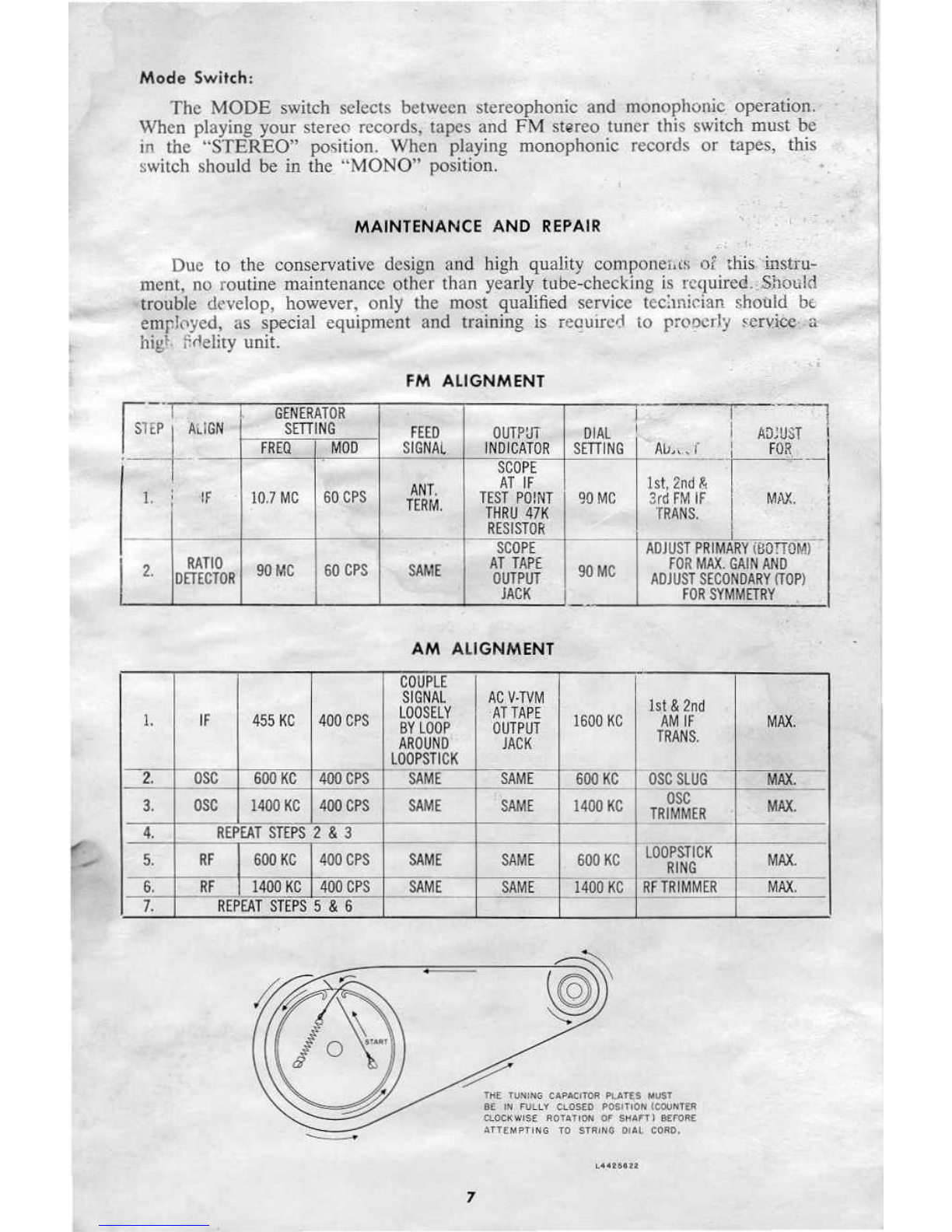
Mode Switch:
The MODE switch selects between stereophonic and monophonic operation.
When playing your stereo records, tapes and FM stereo tuner this switch must be
in the "STEREO" position. When playing monophonic records or tapes, this
switch should be in the "MONO" position.
MAINTENANCE AND REPAIR "
.
'
Due to the conservative design and high quality componei.cs of diis.:.insttu-
ment, no routine maintenance other than yearly tube-checking is rcquired.jShould
trouble develop, however, only the most qualified service technician should. be
employed, as special equipment and training is reouired to properly service a
mgt. f.rlelilYunit.
FM ALIGNMENT
r';
i~lIGN
GENERATOR
I
'-,
SETTING FEED OUTPUT DIAL
ADiour __ I
FREQ MOD SIGNAL INDICATOR SmlNG
Ali..."
j
I
I
-
SCOPE
,
ANT. AT IF
Ist, 2nd
&
(
1.
I
tF 10.7 MC 60 CPS TERM. TEST PO!NT 90 MC
3rd
FM IF
MAX.
THRU 47K TRANS,
RESISTOR
SCOPE ADJUST PRIMARY iBOTTOM)
2.
RATIO 90MC 60 CPS SAME AT TAPE 90MC FOR MAX. GAIN AND
DETECTOR OUTPUT ADJUST SECONDARY (TOP)
JACK FOR SYMMETRY
AM ALIGNMENT
COUPLE
SIGNAL AC V·TVM 1st
&
2nd
LOOSELY 'ATTAPE
I.
IF 455 KC 400 CPS BY LOOP OUTPUT 1600 KC AM IF MAX.
AROUNO JACK TRANS.
LOOPSTICK
2.
OSC 600 KC 400 CPS- - SAME SAME 600Ke ~SCSLUG MAX.
--
3. OSC
14Q0
KC 4Q0 CPS SAME SAME 1400 KC OSC MAX.
TRIMMER
4.
REPEAT STEPS
2
&
3
5. RF 600 KC 4Q0 CPS SAME SAME 600 KC lOOPSTICK MAX.
RING
6. RF 1400 KC 400 CPS SAME SAME 1400 KC RFTRIMMER MAX.
7. REPEAT STEPS 5
&
6
TtiE TUNING CAPACITOR PLATES MUST
BE IN FULLY CLOSED POSITION (COUNTER
CLOCKWISE ROTATION OF SHAFT) BEFORE
ATTEII<P.,ING TO STRING DIAL CORD.
7
,
•
,
•
,
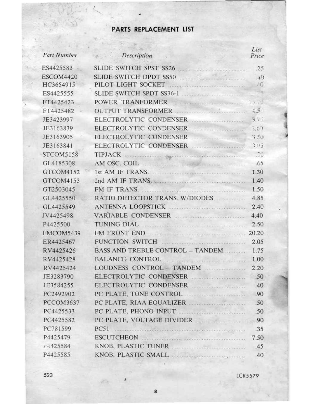
Part Number
ES4425583
ESCo.M442.Q
HC3654915
ES4425555
'.
FT4425423
FT4425482
JE3423997
JE3163839
JE3163905
JE3163841
STCo.M~158
GL4185308
GTCo.M4152
G'fCo.M4153
GTQ503045
GL4425550
'0L4425549
lV4425498
P4425500
FMCo.tvI5439
ER4425467
RV4425426
RV4425428
RV4425424
JE3283790
JE3584255
PC2492902
PCCo.M3637
PC4425533
PC4425582
PC781599
P4425479
r.::125584
P4425585
523
PARTS REPLACEMENT LIST
List
Price
SLIDE SWITCH SPST
SS26 . . ..
SLIDE SWITCH DPDT 8850 . ; .
PILo.T LIGHT So.CKET ..
SLIDE SWITCH SPOT SS36-1 . . . .
POWER TRANFORMER .
•
; r , ~
OUTPUT TRANSFo.RMER .
ELECTRo.L TIIC Co.NDENSER .
ELECTRo.L YTIC Co.NDENSER . ..
ELECTRo.LYTIC Co.NDENSER ..
3:, ..
ELECTRo.L
vrrc
Co.NDENSER
• • •• ~" •• ~ l'
~
).
~
)
TIPJACK ; ~...
.~G
AM o.SC. Co.IL .. .. . . . . . .65
Ist
AM IF TRANS. . ,.... . . 1.30
2nd AM IF TRANS. " ,.... 1.40
FM IF TRANS. . L50
RATIO. DETECTOR TRANS. W/DIo.DES ., 4.85
ANTENNP>. Lo.OPSTICK . .. .. '2.40
VARI ABLE Co.NDENSER . . .., , 4.40
TUNING DIAL .. 2.50
FM FRo.NT END ,.... ., , , 20.20
FUNCTION SWITCH . . . . 2.05
BASS AND TREBLE Co.NTRo.L - TANDBM .., ,..... 1.75
BALANCE· Co.NTRo.L LOO
Lo.UDNESS Co.NTRo.L -TANDEM. 2.20
ELECTRo.L YTIC Co.NDENSER .50
ELECTROL YTIC Co.NDENSER . .40
PC PLATE, To.NE Co.NTRo.L . . .. .90
PC PLATE, RIA A EQUALIZER ,.... .50
PC PLATE, PHo.NO INPUT .. ". . .50
PC PLATE, Vo.LTAGE DIVIDER .90
PC51 ,...... .35
ESCUTCHEo.N ,... 7.50
KNo.B, PLASTlC TUNER '" .45
KNo.B. PLASTIC SMALL . . .. .40
LCR5579
I
8

•
VI
6~Qa/£CCa5
V2
~~ 1/2 €AJa/ECHal
V4
6AU6
V3
6E07
-----------~,.~~~)~
----------.,
..
"'
~I(
r
~'6
,,-
••
"".
'"
<!.10!(
..
/
/
/
/
/
/
,,\I,
06..,6
J\'44~54'$8
,
.
PHONO
LO
.
..
410K
...
.,0K
.....,
HI
...
""
"
•••
)00
...
.....
V6
12AX7
ECCa3
I
NOI5£ FILTERII
I I
I
I
I I
PtiO~
LO
..
,
.t/tow
,.
CHANNEL 8
CM)
.1/400V'
...
,.
OUf
PHONO
HI
=1
I
L
_j
=@
1001(
-
.
~en
,:);'''''
..
~!l
UNltsS O"H~WISE SPECIFU:O-
1- ALI. R£SISTANCE. VAWU IN OHMS
"IO~~
2- ALL
~fSISTOftS
112 WATT.
3- AU. CA,PACIT'QRS Wlflo(
O[CI""~
VALutS IN lotfO.
4_ AU. eAPACltORS W'lT'HOUr D(CtN41 VALUES IN "M',
S -
au.
'JOC.tAG£$
A.qe:
DC •
~y
V/lP.V
.1~~
At 01 OSRESISTANCE
A
•
TUILI
!'WI
I'lN
i'
pm
l
PIN ..
PIt40
PlrHi
""1
PIt4 II
PINt
VI leOt&
V: (CHII
.-
.'01(
0
...
""
"
.
•• 1'1(
m
V.1 tl!:01
•
.:"CIt
e
.>oK
.....
'10'
•
v.....
""'"
o
...
,.
....
0
V~
feet'
.
_
''''.
e
.
.,..
1M
,.
v,
CCCtl
'00'
>.3M
•
*IOOK
'"
OK
117(cel" ""'"
ecc
nOI(
>0.
vt «ecta
)t22J(
,.
... M,,,,
,.
111221(
ve
7"00
--
-
*200
~
...
<I"OK
-
--
-
1/10
140t
*.200
,
...
IITOI(
--
VH ,.401
*,,00
.».
"701'
om
"401
-
-
*'..
....
'10<
--
--
-
--
*
IIU1$UI«(:
JIUDI~$S
kllIKeD ..
n"
A$'C'US"
AM ..(aSWm
'1t06I , ..
eJt,HCTtO!rt OF 1t76 •
en,
1o'9!.''''H ,
"[~"Mct
$1£100,.125,
,uNCrlOfl'
$'111
IH
'M POS .•
rOHI
COffTltOll naT, LCUC1llESS MIN, , ....."""
(.C)NI'JII(IL
C(NT[tlEO.
Moot ''''' STEflEO.
.
...
$41425t316~
MODEL MX601
FM STEREO
~4DAPTER
(
-
,
• -0
"'10.
J
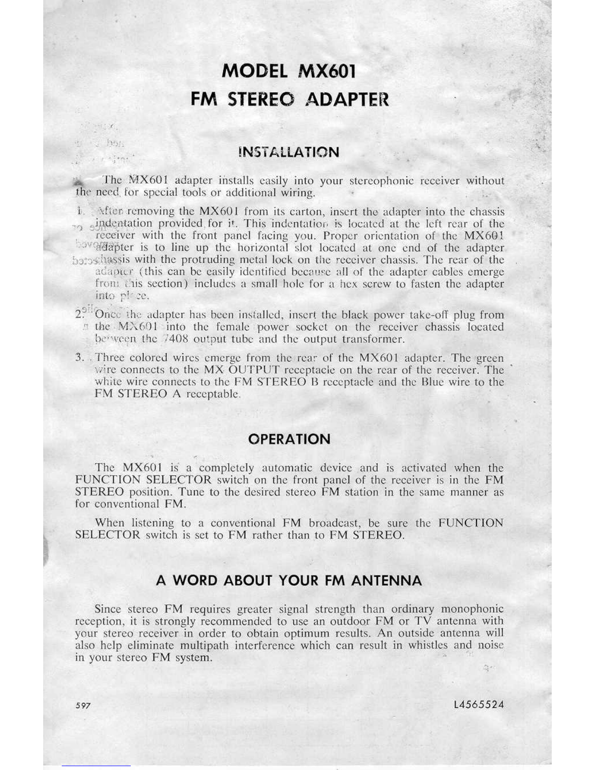
tNSTAllATION
:... The ~601 adapter installs easily into your stereophonic receiver without
thJ> o:e'ed,
tor
special
tools or additional Wiring.
t.
·~ffhn,.re'moving the MX601 from its carton, insert the adapicr iuto the chassis
"') !)ljN.i:\1~rl.aponprovided, for
it
This indentatier- i,sIocarcd at the left re<tr of the:
, reGeIver with the front panel facing you. Proper orientation of the MX601
·'';:iY
'1mat.pter is to line up the
horizontal slot located
at one end of the ;ld<!pter
b3:::)'~l,lt~~iswith
the protruding
metal
leek
on
the
receiver
chassis. TJ1e
Tear
of the
adar.}'l.tf
(this can
be
easily identified
because art
of the adapter cables. emerge
fron: ~;1issection) includes
:'i
small hole for a hex screw to fasten the adapter
i
nto '"
I.
r- ",
.. r ~ ..\._;.
.
,
'
2~"'e>l1Cv
inc adapter has ~),€cninstalled,
inse-rt
the pla~k
pJ)wer
take-off plug from
.'1 the MX601 into the female power socket on the receiver chassis .located
!)e'W,('orll
the /408,outp.ut tube and the output transformer.
3.. Three ec5lored wires emerge from
tl1C
r:c(l~
of tI1e MX601 adapter. Tb'e 'green
wire eennects to the MX- OUTPUT receptacle on the
rear
of the
receiver:
The
white
wire
connects
to the FM STEREO
B
rcccpfuck
and
the Blue
wire to 'the,
FM STE.'REO A receptable.
OPERATION
, ,
The MX60.1 is'. a completely automatic device and
if>
aetiv,tted when the
FUNcrION SELECTOR switch Oil the front
R(lflel
of the receiver
is
ill the FM
STEREO position. Tune to the desired stereo EM station
in
the same manner as
for conventional
PM.
When listening to a convenrional FM br.o(ldta~t;
0'e
sure the FUN<tT'lON
SELECTOR switch is
set
to FM rather
than
to
PM
STEREO.
A WORD
ABOUT YOUR FM ANTENNA
Since
stereo FM requi res greater
.,signal
strength than oLCohnaq m(f)nopboni~,
reception, it
is
strongly recominended
to
use au outdoor .PM or TV antenna with
Your
stereo
receiver in
order to obtain
0ptimtiID
results.
An ol!ltsicie
antenna wjI]
also help eliminate
ll1ultiBatn
intede.renq:) which can re§(ul~in whi.st~s an~
110ise
in your stereo PM system. '"
597
l4565524.

VI
6C4
PCCOM5527
1-
5~
--,oK
IG),.
I
x:
I
82 430
-=-
TO
I
RIGtlT M.X 'NPUT
I
("Hln)
8.2K
~o
L
•
-,-----,
GLCON!V_"~
• I 7.011}'
--_j
-=®
®
R8
50K
~--~~--~-----------.
_.Lcz
~'K
~5"
R5
12K
"
c>
'00
<D
<D
PCCOM5527
TO
LEFT
MJ(
INPUT
r
SJK
I~K
l
18LUE)
I
I
82
430
16>
-e-
I
'~J
f-J
I
I
L
V, V2
=®..
~
230V
+~
RIO
...
~30V
R'8
I.SK/IW
r---
....,
I
CIOA
~
I
I'OOV
I
I
CI08
I
I
30"'0
I
.<>0
V
L
-=
-'V 2
6t·_-J/ ECF80
T3
C9
G-LCOM54221
150
GLCOM6t70
r--
l,r
I
I
I
-. C8
I
1.5K I
5%
_j
l
Rl7
lOOK
C7
I4MFD
-=
3»1
230V
2
AOAPTER
SOCKET
RES ST
READ NOS
I
ANCE
I
..
I
P,N I p,n 2
T
p,n
3
1
p'N'l
PIN'
~'.'''F.
PIN6
PIN 7
PIN& Pln 9
,~.
.::..:::.I, _
-J:__
'*
45.
bv· ~
~'4~K
''''
,.
~a,.•-
1~'4#"
2'!J"!'*'cii?,q
_c ..
f-
*
8Jl.
IK
3.3K
'"
~
UNLESS OTHERWISE SPECIFIED-
t -
AU- RESISTANCE VAtI.UES IN 'OHMS %10%.
2 - ALI. RESISTORS
1/2
WATT •
3 -
ALl. CAPACITORS WITH DEC.IMAL VALU'[S IN
MFO.
4 - AL.LCAPACITORS WJTHOUl DECIMAL VALUES IN tltM',
5 -
ALL VOL.TAGES ARE DC
a
MAY vARY
i:
20 %.
S597
S45764168
... lir::U("'ANcr .READINGS
~~EO
w:p;i
ASTERISK ARE; MEASUREO
fRO)..
TH~ .;t}N~IION O~ IfIS
s:
ClOP,
FM 5T~9EO
ADAPTER
w
.)
<D
....
.)
§
~
~
..
z
w
W
"-
'"
a::
..
0
::>
'5
..
0
0
~
w
w
e:
0
w
0
..
z
;;:
..
'"
a::
.. 0
Q.
s
l-
S
0"
«
w'"
0-
J",
..
0
0
wZ
I-
Z
..
'_Ww
~
W
(h ....
'"
::;;
'"
0
..
.,
J"
:t
Z
..
~C{q)~&IJ
<.0
J
..Jzo>o
Z
:>
a,t:l..J ...
..J
j:0:>2
"
...
.) <>
0
2
i~~~~
..
x
:Ii
II
I
I
,
z
W
'"
_NI<)ql(>
-"
J
0-
~
0-
..I
...
::;)
..
"
::;;
w
..
!;(
..
0
z
0
0
..
i
e
'" '"
:e
::> ::> ::> ::>
... '"
'" '"
:E
'"
it
;(
~
%
::>
~
:i ,
<t
:.1
Q
:E
:E.
"
~
0<
...
"
s:
~~~
'"
0-
~
"'0'"
::>
.... ....
IJ..~
e
~
:;~
......
0:E~
Q
..
000
0..0°
"
..
~
"", 0,."
...
"
CO<
~m
"I?
~€>
w
'"
~~ui
~
..
:0
'"
0&2
.....
~~
<t
"
Q
:l
::>0
on
..
0"
....
:
-
",
...
4
..~o
..
z
'"
zea ......J
...
w
;;;
0
zZ ..
w-Wz:
'"
"
Q
"'fZ~
~~
w
~1.IJ2;;;
'"
...
.. ..
!I
,."5
a:
15::1
wg~....
I'?
'"
.
«
"'
..
..J
00
oJ
W
..
20
«
WIU
w
~
"-
'"
Zl-1t2
..
g ..
gj~~
<t
Z
.. ..
.. .. ...
III :::HIIX
'"
..
" v
..
~glD""
.;
'"
w
..
Z
.)
Z
Z
"
<D
..
"
~~
::>
CO<
:;
;:
",0
N"
1-
0I-
~
... ...
!I
"
"
~
<D
!!l
'"
..
'"
-
..
'"
q
..
..
Table of contents


