CHWS PRORAPID User manual

CHWS PRORAPID
SEMI INSTANTANEOUS DHW GENERATOR
Installation Manual
Operation & Maintenance Manual
2| INSTALLATION MANUAL PRORAPID
PF
PR
PHE
CONTROLLER
I
CHWS ProRapid
Semi Instantaneous DHW Generator
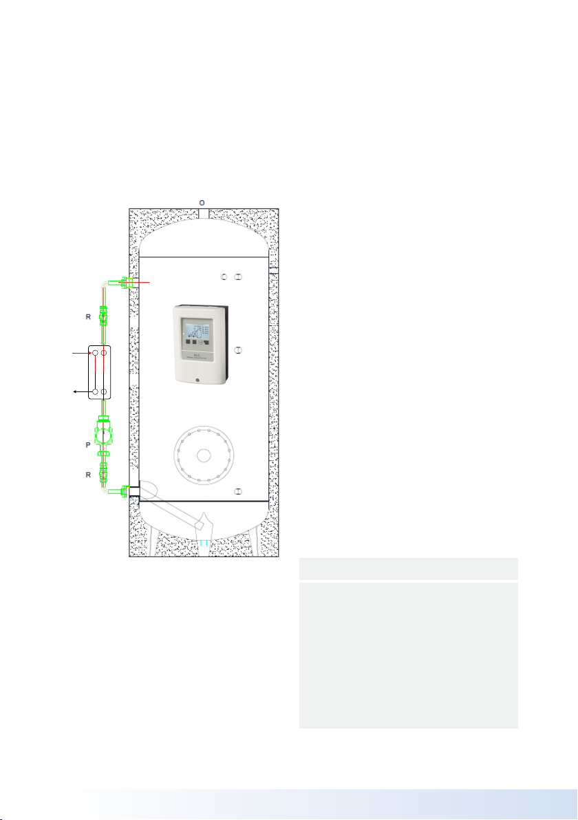
General Layout
Sanitary hot water outlet
Inlet cold water
Plate Heat Exchanger
Circulation pump
Isolating valve
Water recirculation
Primary return
Primary ow
Controller
Key
O
I
PHE
P
R
WR
PR
PF
C
Fig. 1

3
INSTALLATION MANUAL PRORAPID |
Instructions For Use
General Information
This instruction manual is a part of the
product, check that it is always supplied
with the CHWS ProRapid DHW generator.
Carefully read the instructions contained
in this chapter as they provide important
information on the usage of the unit.
Keep this manual for future reference if the
CHWS ProRapid DHW generator is sold or
transferred to a dierent owner or leaving
the unit where installed, please make sure
that this manual always accompanies the
CHWS ProRapid DHW generator so as it
can be used for reference by the new owner
or installation expert.
Important: This CHWS ProRapid Hot
water generator has to be used to produce
hot sanitary water, in accordance with its
technical features of performance and
power, by thermal exchange with a heating
water supply (t ≤ 100°C) max.
Any dierent usage for the CHWS ProRapid
Hot water generator is forbidden, do not
clean the CHWS ProRapid Hot water
generator with corrosive or ammable liquids.
The use of electric adapters, extension
cords or socket sets is not recommended.
In case of damages to the electric cord turn
the power o and consult a professionally
qualied technician.
An electric manual is enclosed in the
appliance please observe the following
fundamental rules:
• Do not touch the appliance with parts
of the body which are wet, damp or in
bare feet
• Do not pull the electric wires
• Do not allow children or unqualied
persons to use the appliance
The manufacturer declines any responsibility
for damages caused by neglect of the
appliance or system. If the CHWS ProRapid
hot water generator is not used for long
periods of time, turn o thepower supply
and empty the unit.
Description
The CHWS ProRapid DHW generators is
manufactured in stainless steel and is able
to satisfy high requirements of sanitary hot
water. The automatic system of water mixing
will avoid temperature’ stratication the heat
storage is therefore higher. The external
stainless steel plate exchanger enables easy
maintenance and cleaning.
The system will reduce the potential for
Legionella growth in an eective way by
heating the stored contents and circulating
water through the entirety of the cylinder.

4| INSTALLATION MANUAL PRORAPID
Periodical Checks
Periodic checks of the units must be
performed by qualied personnel in order to
guarantee the appliance eciency
and correct system operation, regular
maintenance is recommended to ensure
optimum operational performance and
tomeet safety requirements.
In the event that problems do occur during
the hot water generation, turn it o and do
not attempt to repair it please consult a
qualied technician.
Important Information
These instructions must be read and
understood before installing, commissioning,
operating or maintaining the equipment.
Installation & Commissioning
Read this installation and commissioning
manual and where necessary refer to
appendix C before commencing, the
CHWS ProRapid semi instantaneous DHW
Generator is a controlled service as dened
in the latest edition of the building regulations
and should only be tted by a competent
person. Installation & Commissioning of
equipment by accredited agents or specialist
sub-contractors will ensure the equipment is
operating safely and eciently.
The installation should also be in
accordance with the British Standard Codes
of Practice, current Building Regulations,
, i.e. Health & Safety Document No. 635
(The Electricity At Work Regulations
1989), and the Water Supply (Water
ttings) Regulations, BS 5449:1990
Forced circulation hot water systems , BS
6700:2006 Design, installation, testing and
maintenance of services supplying water.
The relevant regulations are: England and
Wales – Building Regulation G3; Scotland
– Technical Standard P3; North Ireland –
Building Regulation P5.
Failure to install this appliance correctly
could lead to prosecution and will invalidate
the guarantee.
It is in your own interest and that of safety to
ensure that the law is complied with.

5
INSTALLATION MANUAL PRORAPID |
Installation Instructions
General Information
This instruction manual is an integral and
essential part of the product check that it is
always furnished with the CHWS ProRapid
DHW generator.
Carefully read the instructions contained
in this chapter as it provides important
information for the correct and safe
installation and use of the appliance.
After the installation please deliver this
manual to the user. The installation and
start-up operations must be performed by
professionally qualied technicians having
the specic skills required in the heating
system sector.
The manufacturer declines responsibility for
any damage to persons or property caused
by a faulty installation or start up.
Important: This appliance should be used
only for the purpose mentioned any otheruse
is improper and therefore dangerous. Before
performing any operation on the appliance,
turn o the electric power supply and close
the water supply tap.
The use of any electric component involves
the observance of the following fundamental
rules:
• Always turn o the electric power
supply switch before touching any
electrical connection
• Do not touch the appliance with parts
of the body which are wet, damp or in
bare feet
• Do not pull the electric wires
• Do not expose the appliance to
atmospheric conditions
• Do not leave the appliance on when
not in use always turn the water and
electric supplies o.
Start Up
Before starting up the CHWS ProRapid
DHW generator, check that the unit is not
damaged if in doubt, do not use it and
contact CHWS Ltd.
The transport and positioning of the
appliance should be carefully performed
with the proper lifting hook. Avoid banging
or forcing the control board and the
insulation. The installation should be
performed in a suitable environment.
The CHWS ProRapid is suitable for
operating at 6 bar working pressure both for
sanitary and heating purposes. In the event
that the hydraulic pressure is higher than 6
bar, insert a pressure reducer in the
sanitary water supply.
Always cover both the sanitary hot
water and the heating water pipes with
an insulating coating according to the
regulations in force.

6| INSTALLATION MANUAL PRORAPID
Packaging components (plastic bags, etc.)
are potential danger and should not be left
within the reach of children.
The electrical safety of the equipment is
achieved when correctly connected to an
ecient grounding system performed
according to the regulations in force. This
fundamental safety requirement must be
veried.
If in doubt, request installation of the
electrical system by professionally qualied
personnel. CHWS Ltd declines responsibility
for damages caused by neglecting
grounding the system.
Gas, hydraulic and heating pipes cannot
be used as grounding. Serious damages to
pipes may occur within a short period of time.
The use of electric adapters, extension
cords or socket sets is not recommended.
Each appliance must be connected to the
electrical system by using a double-pole
switch according to the regulations in force.
The use of any component run by electrical
power involves the observance of the
following fundamental rules:
• Always turn o the electric power
supply switch before touching the
electrical connections
• Do not touch the appliance with parts
of the body which are wet, damp or in
bare feet
• Do not pull the wiring
• Do not expose the appliance to
atmospheric conditions (rain, sun, etc.)
Loading System
In case the external temperature is very low,
keep the temperature of the room where the
CHWS ProRapid DHW generator is installed
over 0°C when the hot water generator is
not in use, in order to avoid bursting due to
frost damage (the warranty does not cover
damages due to frost).
Fill the CHWS ProRapid by using the
hydraulic system check that the sanitary
water safety valve and the drain work
properly. Before lling the heating circuit with
water, clean the system carefully in order to
remove dirt and any residual substance that
may cause scale or damage.
Operation
Before turning the system on check that:
• The pipe connections are completely
sealed
• The system is equipped with safety
devices and controls according to the
regulations in force.
• The hot water pipes are insulated.
7
INSTALLATION MANUAL PRORAPID |
ProRapid - Semi Instantaneous DHW Generator
COMMERCIAL HOT WATER SOLUTIONS LTD
The Hive, Weston-super-Mare. BS24 8EE, United Kingdom
rapid/tps/feb2021/v1
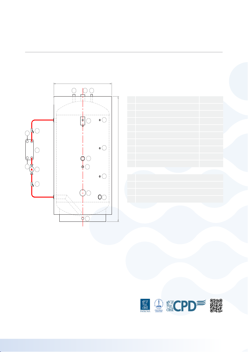
A
B
5 43
6
6
6
10
9
8
7
D
1
A
B
C
A
2
2
Connections
1 Drain
2 Primary Connections
3 DHW Outlet
4 Temperature & Pressure Relief Valve
5 Anti-Vac Valve
6Sensor Tappings (x3)
7 Electrical Immersion Tapping
8 DHW Return
9Inspection Hatch / Electrical Immersion
10 Cold Water Inlet
A Isolation Valve
B Charging Pump
C Brazed Plate Heat Exchanger
D Control Panel
Drawing correct at time of publishing, some minor changes in design may occur which will not aect performance.
8| INSTALLATION MANUAL PRORAPID
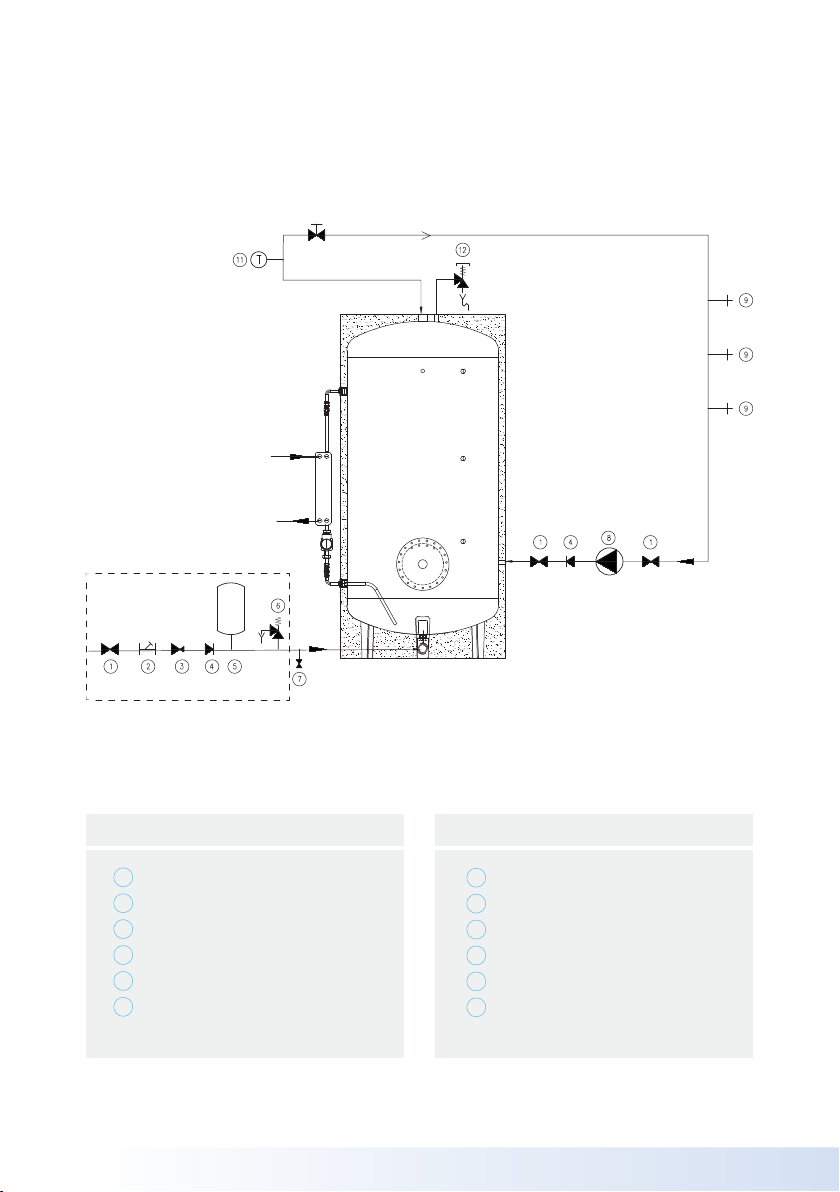
UNVENTED KIT
COLD WATER INLET
LTHW RETURN
LTHW INLET
HOT WATER DHW OUTLET
SECONDARY RECIRCULATION
Appendix C
Drain
Circulation pump (optional)
Draw-o points
Service stop valve
Temperature gauge (optional)
T&P valve
Isolating valve
Strainer
Pressure reducing valve
Non return valve
Expansion vessel
Safety relief valve
Key
1
2
3
4
5
6
7
8
9
10
11
12

9
INSTALLATION MANUAL PRORAPID |
Maintenance Instructions
General Instructions
Read carefully the instructions contained
in this chapter as they provide important
indications on the use and maintenance
of the appliance. Before performing any
operation on the CHWS ProRapid DHW
generator, turn o the electric power supply
switch and close the water supply valve.
The use of any component which is
electrically supplied entails the close
observance of the following fundamental
rules:
• Always turn o the electric power
supply switch before touching any
electrical connection
• Do not touch the appliance with parts
of the body which are wet, damp or in
bare feet
• Do not pull the wiring
• Do not expose the appliance to
atmospheric conditions
Substitute parts or accessories of the
appliance with original spare parts only. Do
not leave the appliance on when not in use.
Always turn the water and electric supply
switches o.
Emptying The CHWS ProRapid
DHW Hot Water Generator
Remove the electric supply and close the
cold water supply and empty the CHWS
ProRapid DHW generator by opening the
valve at the bottom of the tank. In case a
vacuum circuit breaker was not inserted in
the sanitary water circuit, insure that a valve
is open at the top of the vessel to vent the
vessel and avoid a damaging vacuum.
Troubleshooting
In case the heat exchange is not heating
suciently, the cause can be:
• The boiler power is not sucient
• The circulation of heating water is
not sucient because of a faulty or
undersized pump
• The temperature of the heating water
entering the ProRapid Plate Heat
exchanger is too low
• The temperature of the sanitary water is
too low or the temperature is too high
• The ProRapid is overused in
comparison with its performance
• Calcium deposits or other deposits in
the heat exchanger
The above listed causes must be veried by
professionally qualied personnel.

10 | INSTALLATION MANUAL PRORAPID
Warranty conditions for
ProRapid® cylinders
General warranty
CHWS Ltd will within a period of 5 years
from the date of purchase of the vessel,
supply a new and replacement cylinder of
the equivalent size and quality if the cylinder
is proved to be leaking or corroding due
to faulty manufacture or material defects.
Claims must be validated by CHWS Ltd who
will also have sole discretion on the validity
of any claim.
Components supplied by CHWS Ltd with
the cylinder will carry their manufacturers
warranty of 1 year. CHWS Ltd will repair
or replace any of these components that
have failed due to manufacturing or material
defects within that 1-year period. The
validity of any claim for faulty components
will be decided by the manufacturer of
that component.
Cylinder warranty
• The warranty on the ProRapid range
of products applies only to cylinders/
vessels supplied for use with sanitary/
drinking water.
• The products covered are the
ProRapid® models.
• CHWS Ltd will provide a 5 Year
warranty on the products as stated in
clause 2 as above.
• The warranty will only apply subject to
observance of the following conditions:
1. The cylinder should be installed in
accordance with the manufacturer’s
installation instructions
2. The cylinder should be installed in
accordance with National and Local
Building Regulations and observing all
relevant installation regulations at the
time of installation.
3. The cylinder is only used for the
purpose it was designed for, that being
the heating and storing of sanitary/
drinking water.
4. The design water temperatures or
pressure values displayed on the
cylinder data plate are not exceeded
during use at any time.
5. The cylinder is installed in a suitable
area that is not in a damp or corrosive
environment
6. In hard water areas, suitable water
conditioning or softening equipment
should be installed to condition the
sanitary water prior to heating. The
acceptable level of water hardness
is between 0 - 0.4 on the Langelier’s
Index of water measured at the
cylinder’s working temperature.

11
INSTALLATION MANUAL PRORAPID |
7. The cylinder should be periodically
maintained in accordance with the
manufacturers servicing schedule
which will include keeping any
sacricial anodes installed into the
cylinders serviceable.
8. Damage to the cylinder by an
external factor, misuse, neglect (this
includes frost damage), unauthorised
modications or attempts to repair
any leak or defect (other than by an
authorised and approved service
engineer) will invalidate any claim.
9. ALL claims must be authorised
by CHWS Ltd before any work or
replacement of defective components
takes place.
Limitations of warranty
CHWS Ltd will supply free of cost
replacement cylinders and components
including delivery to the original delivery
address of the cylinder. CHWS Ltd will not
accept any charges for the cost of labour,
installation or any other associated costs
with the installation of the replacement
cylinder or ancillary component.Claims must
be validated by CHWS Ltd who will also
have sole discretion on the validity of
any claim.
12 | INSTALLATION MANUAL PRORAPID
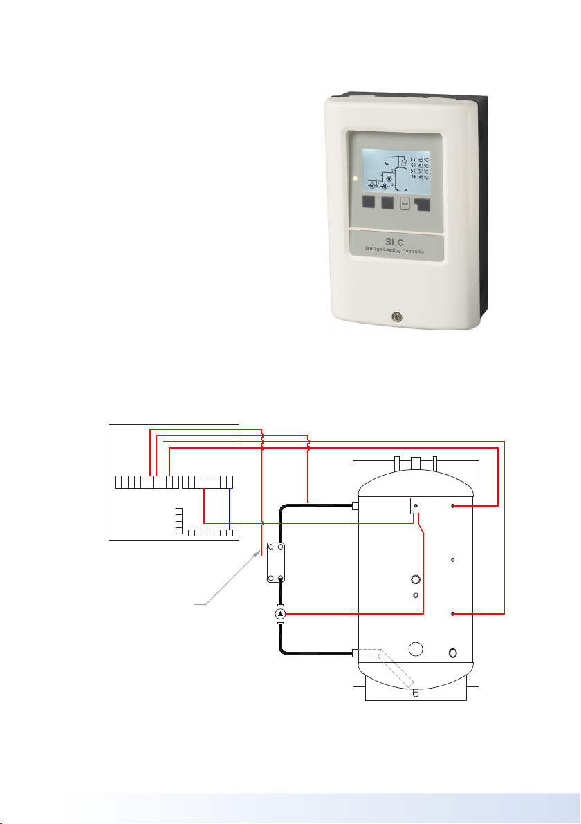
+ S6 V2 V1 S5 S4 S3 S2 S1 - R4 R4i R3 R2 R1 L N
NN
NN
NN
N
E
E
E
E
CIRCULATING
PUMP
HEAT
EXCHANGER
SLC CONTROLLER
PRO-RAPID VESSEL
PT1000 PROBE
WIRED AS SHOWN TO PRO-RAPID CONTROLLER
AND LEFT COILED FOR INSTALLER TO FIT
ONTO PIPEWORK
Storage Loading
Controller SLC
Installation and operating
instructions
Read carefully before installation,
commissioning and operation.

13
INSTALLATION MANUAL PRORAPID |
Safety Instructions
EU-Conformity
By axing the CE mark to the unit the
manufacturer declares that the SLC
conforms to the following relevant safety
regulations:
• EU low voltage directive 2014/35/EU
• EU electromagnetic compatibility direc-
tive 2014/30/EU conforms.
Conformity has been veried and the
corresponding documentation and the EU
declaration of conformity are kept on le by
the manufacturer.
General instructions
Please read carefully!
These installation and operating instructions
contain basic instructions and important
information regarding safety, installation,
commissioning, maintenance and the
optimal use of the unit. Therefore these
instructions must be read and understood
completely by the installation technician/
specialist and by the system user before
installation, commissioning and operation of
the unit.
This unit is an automatic, electrical Storage
Loading Controller. Install the unit only in dry
areas and under the ambient conditions
described in “Specications”.
The valid accident prevention regulations,
VDE regulations, the regulations of the
local power utility, the applicable DIN-EN
standards and the installation and operating
instruction of the additional system
components must also be observed.
Under no circumstances does the unit
replace any safety devices to be provided by
the customer!
Installation, electrical connection,
commissioning and maintenance of the
device may only be carried out by an
appropriately trained specialist. Users: Make
sure that the specialist gives you detailed
information on the function and operation of
the unit. Always keep these instructions in
the vicinity of the unit.
The manufacturer does not take over any
liability for damage caused through improper
usage or non-compliance of this manual!

14 | INSTALLATION MANUAL PRORAPID
Danger Failure to observe
these instructions can result
in electrocution.
Danger Failure to observe
these instructions can result
in serious damage to health
such as scalding or life-
threatening injuries.
!
Caution Failure to observe
these instructions can result
in destruction of the unit or
the system, or environmen-
tal damage.
Caution Information which
is especially importation for
the function and optimal use
of the unit and the system.
Explanation of Symbols
Changes to the Unit
• Changes, additions to or conversion of
the unit are not permitted without writ-
ten permission from the manufacturer.
• It is likewise forbidden to install ad-
ditional components that have not been
tested together with the unit.
• If it becomes clear that safe operation
of the unit is no longer possible, for
example because of damage to the
housing, turn the Unit o immediately.
• Any parts of the unit or accessories
that are not in perfect condition must
be exchanged immediately.
• Use only original spare parts and ac-
cessories from the manufacturer.
• Markings made on the unit at the fac-
tory must not be altered, removed or
made illegible.
• Only the settings described in these
instructions may be set using the Unit.
Changes to the unit can
compromise the safety and
function of the unit or the
entire system.
Warranty and Liability
The Unit has been manufactured and
tested with regard to high quality and safety
requirements. The warranty and liability shall
not include, however, any injury to persons
or material damage that is attributable to
one or more of the following causes:
• Failure to observe these installation and
operating instructions.
• Improper installation, commissioning,
maintenance and operation.
• Improperly executed repairs.
• Unauthorised structural changes to the
unit.

15
INSTALLATION MANUAL PRORAPID |
• Use of the device for other than its
intended purpose.
• Operation above or below the limit
values listed in the ‚Speci cations‘
section.
• Force majeure.
Disposal and Pollutants
The unit conforms to the European RoHS
2011/65/EU for 2011/65/EUthe restriction of
the use of certain hazardous substances in
electrical and electronic equipment.
Under no circumstances
may the device be
disposed of with the
normal household waste.
Dispose of the unit only at
appropriate
collection points or ship
it back to the seller or
manufacturer.

16 | INSTALLATION MANUAL PRORAPID
Description Slc
Specications
Electrical specications:
Power supply 100 - 240VAC, 50 - 60 Hz
Power consumption / standby 0,5W - 2,5W/ X
Internal fuse 1 2A slow blow 250V
Protection Class IP40
Protection Class II
Overvoltage category II
Degree of pollution category II
Inputs/Outputs
Sensor inputs 6 -40 °C ... 300 °C
Outputs mechanical relay 3
mechanical relay R1 - R3 460VA for AC1 / 460W for AC3
0-10V/PWM output V1 - V2 for 10 k Ω working resistance 1 kHz, level 10 V
Max. cable length
Flow sensors <3m
0-10V/PWM <3m
mechanical relay <10m
Permissible Ambient Conditions
for controller operation 0 °C - 40 °C, max. 85 % rel. humidity at 25 °C
for transport/storage 0 °C - 60 °C, no moisture condensation
permitted
Other Specications and Dimensions
Housing design 2-part, ABS plastic
Installation methods Wall installation, optionally panel installation
Overall dimensions 163 mm x 110 mm x 52 mm
Aperture installation dimensions 157mm x 106mm x 31mm
Display completely graphic display 128 x 64 dots
Real Time Clock RTC with 24 hour power reserve
Operation 4 entry keys

17
INSTALLATION MANUAL PRORAPID |
Terminal: Connection for:
S1 Storage top
S2 Storage bottom
S3 Plate outlet temp
S4* Primary Flow Temperature
S5 Not used
V1 Not used
V2 Not used
S6 Not used
+ 12V Power supply
VFS1 Not used
VFS2 Not used
The connection of the ground wire is
made at the lower gray terminal
block.
CAN Not used
Terminal: Connection for:
S1 Neutral conductor N
S2 Phase conductor L
S3 240vac Switch Live Burner
S4* Not in use
S5 Not in use
V1 Secondary pump live
The neutral conductor N must be
connected to the N terminal block.
The PE protective conductor must be
connected to the PE metal terminal block!
Installation
Electrical Terminals
Low voltages
max. 12 VAC / DC
Mains voltages
100 - 240 VAC, 50 - 60 Hz

18 | INSTALLATION MANUAL PRORAPID
Before working on the unit, switch o the power supply and secure it against
being switched on again! Check that there is no power owing! Electrical
connections may only be made by a specialist and in compliance with the
applicable regulations. The unit may not be put into operation if there is
visible damage to the housing, e.g. cracks.
The unit may not be accessible from behind.
Low-voltage cables such as temperature sensor cables must be routed
separately from mains voltage cables. Feed temperature sensor cables only
into the left-hand side of the unit, and mains voltage cables only into the
right-hand side.
The customer must provide an all-pole disconnecting device, e.g. an
emergency heating switch.
The cables being connected to the unit must not be stripped by more than 55
mm, and the cable jacket must reach into the housing just to the other side of
the strain relief.
Cable Installation
1. Unscrew cover screw completely.
2. Carefully pull upper part of housing
from lower part. During the removal, the
brackets are released as well.
3. Set upper part of housing aside. Do not
touch the electronics.
4. All terminals are “spring cage” type
terminals. To open the terminal use a
terminal screw driver to push in the
spring and insert your cables. It is
recommended to use “boot lace” type
connections.
5. Once all cabling is completed, check
that no mains voltage cables have been
installed on the low voltage side.
6. Put on the cover and screw cover
completely.
Electrical Connection

19
INSTALLATION MANUAL PRORAPID |
Before working on the unit, switch o the power supply and secure it against
being switched on again! Check that there is no power owing! Electrical
connections may only be made by a specialist and in compliance with the
applicable regulations. The unit may not be put into operation if there is
visible damage to the housing, e.g. cracks.
The unit may not be accessible from behind.
Low-voltage cables such as temperature sensor cables must be routed
separately from mains voltage cables. Feed temperature sensor cables only
into the left-hand side of the unit, and mains voltage cables only into the
right-hand side.
The customer must provide an all-pole disconnecting device, e.g. an
emergency heating switch.
The cables being connected to the unit must not be stripped by more than 55
mm, and the cable jacket must reach into the housing just to the other side of
the strain relief.
Installing the Temperature Sensors
The controller operates with Pt1000
temperature sensors which are accurate
to 1 °C, ensuring optimal control of system
functions.
!
If desired, the sensor cables
can be extended to a
maximum of 30 m using a
cable with a cross-section
of at least 0.75 mm².
Ensure there is no contact
resistance! Position the
sensor precisely in the area
to be measured! Only use
immersion, pipe-mounted
or at-mounted sensors
suitable for the specic
area of application with the
appropriate permissible
temperature range.
Low-voltage cables such as
temperature sensor cables
must be routed separately
from mains voltage cables.
Feed temperature sensor
cables only into the left-
hand side of the unit, and
mains voltage cables only
into the right-hand side.
Temperature Resistance Table for
Pt1000 Sensors
°C Ω
-20 922
-10 961
0 1000
10 1039
20 1077
30 1116
40 1155
50 1194
60 1232
70 1270
80 1308
90 1347
100 1385

20 | INSTALLATION MANUAL PRORAPID
Operation
Display and Input
The display‘s (1), extensive text and
graphical mode, enables simple, almost self-
explanatory, operation of the controller.
The LED (2) lights up green when the
primary pump is switched on (automatic
mode). The LED (2) lights up red when
operating mode‚O‘ is set. The LED (2)
ashes quickly red when an error is present.
Entries are made using 4 keys (3+4), to
which contextual functions are assigned.
The ‚esc‘ key (3) is used to cancel an entry
or to exit a menu. If applicable, a request
for conrmation appears to save the made
changes.
The function of the other 3 keys (4) is shown
in the display right above the keys. The
right-hand key generally has a conrmation
and selection function.
The graphics mode appears if not key is
pressed for 2 minutes or after exiting the
main menu with ‘esc’.
Hitting the “esc” key in the graphics mode
takes you directly to the main menu.
Exit main menu
2. Statistics
1. Measurements
OK
Pump (rotates when active)
Storage / buer
Temperature Sensors
Heat exchanger
Further symbols can be found
in the special functions
Key
+/-
Yes/No
About
Back
Ok
Conrm
/
Increase / decrease values
Scroll menu down / up
agree / reject
further information
to the previous display
Conrm selection
Conrm setting
Examples for key settings:
58ºC
55ºC
100%
16.0| min
Table of contents
Other CHWS Industrial Equipment manuals

Popular Industrial Equipment manuals by other brands


Genmitsu
Genmitsu PROVerXL 4030 CNC user manual

Pfeiffer Vacuum
Pfeiffer Vacuum HIPACE 700 P operating instructions

Vector
Vector OPT1-FC-HTNV-VC operating instructions

Oxford Instruments
Oxford Instruments MicrostatHe user manual

Eaton
Eaton Airflex WCB Series Installation, operation and maintenance

Montanari
Montanari RQ 200 manual