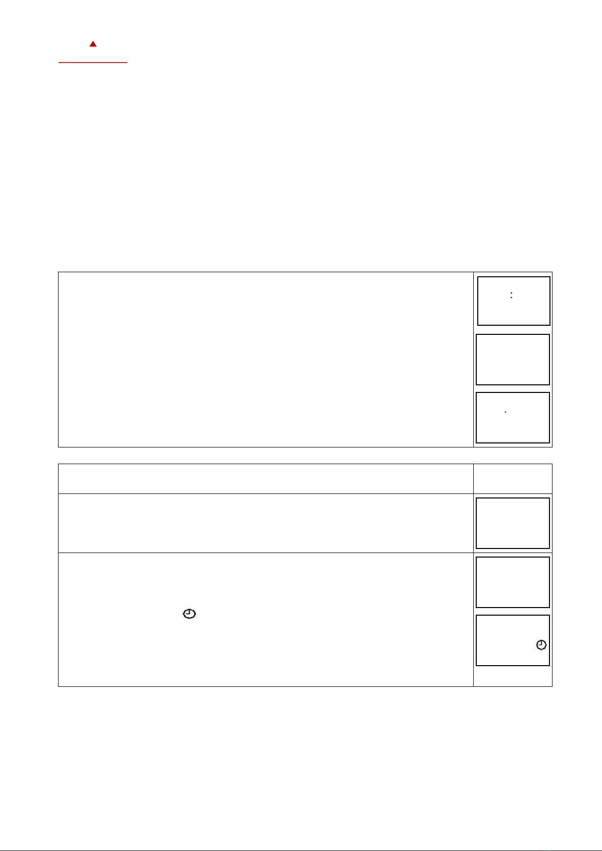
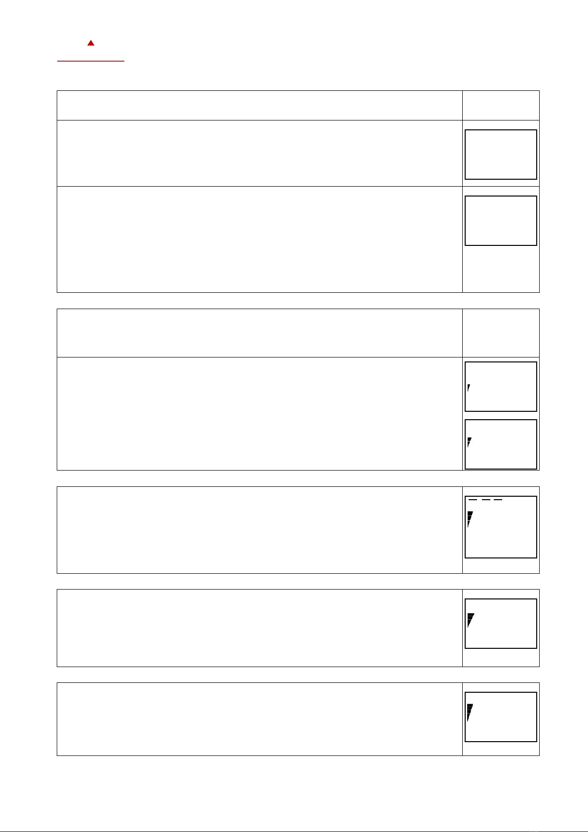
Vector OPT1-FC-HTNV-VC User manual

X2-OPERATING MANUAL
WITH TOUCH SCREEN
Doc: 70-00-0741, Serie X2, 20190213 © Vector Controls GmbH, Schweiz Page 1
subjects to alteration www.vectorcontrols.com
VECTOR
Operating instructions Touch devices of
the X2 operating system
The X2 operating system was designed for universal controllers and sensors. Devices based on the X2
operating system contain a multitude of standardized functions and application possibilities. From simple
ventilation controllers for domestic applications to HVAC system solutions for entire buildings. There is a
suitable solution for almost every application. With the EasySet program, the controllers can be
conveniently read out, programmed and transferred to other controllers.
Applications
These operating instructions apply to devices of the X2-series devices using the OPT1 series touch panel HMIs. The FC
series is suitable for the Feller EDIZIOdue® frame.

X2-OPERATING MANUAL
WITH TOUCH SCREEN
Doc: 70-00-0741, Serie X2, 20190213 © Vector Controls GmbH, Schweiz Page 2
subjects to alteration www.vectorcontrols.com
VECTOR
Ordering
Model
Items
Description
OPT1-FC-HTNV-VC
40-500110
Remote operation terminal with an internal temperature and humidity sensor, a passive input and a
voltage input for Feller EDIZIOdue® frames.
OPT1-FC-TNV-VC
40-500111
Remote operation terminal with an internal temperature sensor, a passive input and a voltage input
for Feller EDIZIOdue® frames.
OPT1-F-HTNV-VC
40-500112
Remote operation terminal with an internal temperature and humidity sensor, a passive input and a
voltage input.
OPT1-F-TNV-VC
40-500113
Remote operation terminal with an internal temperature sensor, a passive input and a voltage input.
OPT1-FA-TNV-VC
40-500136
Remote operation terminal with an internal temperature sensor, a passive input and a voltage input
packed with AMM-AD-W.
OPT1-FU-TNV-VC
40-500116
Remote operation terminal with an internal temperature sensor, a passive input and a voltage input
packed with AMM-UD-W.
OPT1-FA-HTNV-VC
40-500135
Remote operation terminal with an internal temperature and humidity sensor, a passive input and a
voltage input packed with AMM-AD-W.
OPT1-FU-HTNV-VC
40-500137
Remote operation terminal with an internal temperature and humidity sensor, a passive input and a
voltage input packed with AMM-UD-W.
OPT1-FE-TNV-VC
40-500139
Remote operation terminal with an internal temperature sensor, a passive input and a voltage input.
AMM-ED-W
40-510086
Frame and mounting plate for Feller EDIZIOdue
AMM-AD-W
40-510089
Frame and mounting plate for the square junction box
AMM-UD-W
40-510090
Frame and mounting plate for the rectangular junction box
In addition, the various product descriptions and the programming instructions for technicians are contained in separate
documents. This should facilitate the work with the different controllers and operating levels.

X2-OPERATING MANUAL
WITH TOUCH SCREEN
Doc: 70-00-0741, Serie X2, 20190213 © Vector Controls GmbH, Schweiz Page 3
subjects to alteration www.vectorcontrols.com
VECTOR
Display and Operation
Key Layout
Display and Operation
Occupied (Comfort): All control functions according to setpoint
Unoccupied (Standby, Economy): Setpoint and power reduced
OFF
Energy hold OFF (EHO): All outputs switched off, inputs for alarms monitored
Heating active
Cooling active
Fan active
Manual override, delay for release function
Schedule set
Control loop display
Target value/parameter description
Actual value/parameter description
Display of the operating mode
Vertical Bar
LEFT Button
DOWN Button
RIGHT Button
UP Button
HEAT/COOL
CLOCK

X2-OPERATING MANUAL
WITH TOUCH SCREEN
Doc: 70-00-0741, Serie X2, 20190213 © Vector Controls GmbH, Schweiz Page 4
subjects to alteration www.vectorcontrols.com
VECTOR
Idle Display
•The idle display is activated if no key is pressed for 30 seconds.
•The idle display can be deactivated by the technician. In this case, the last active setpoint is still displayed.
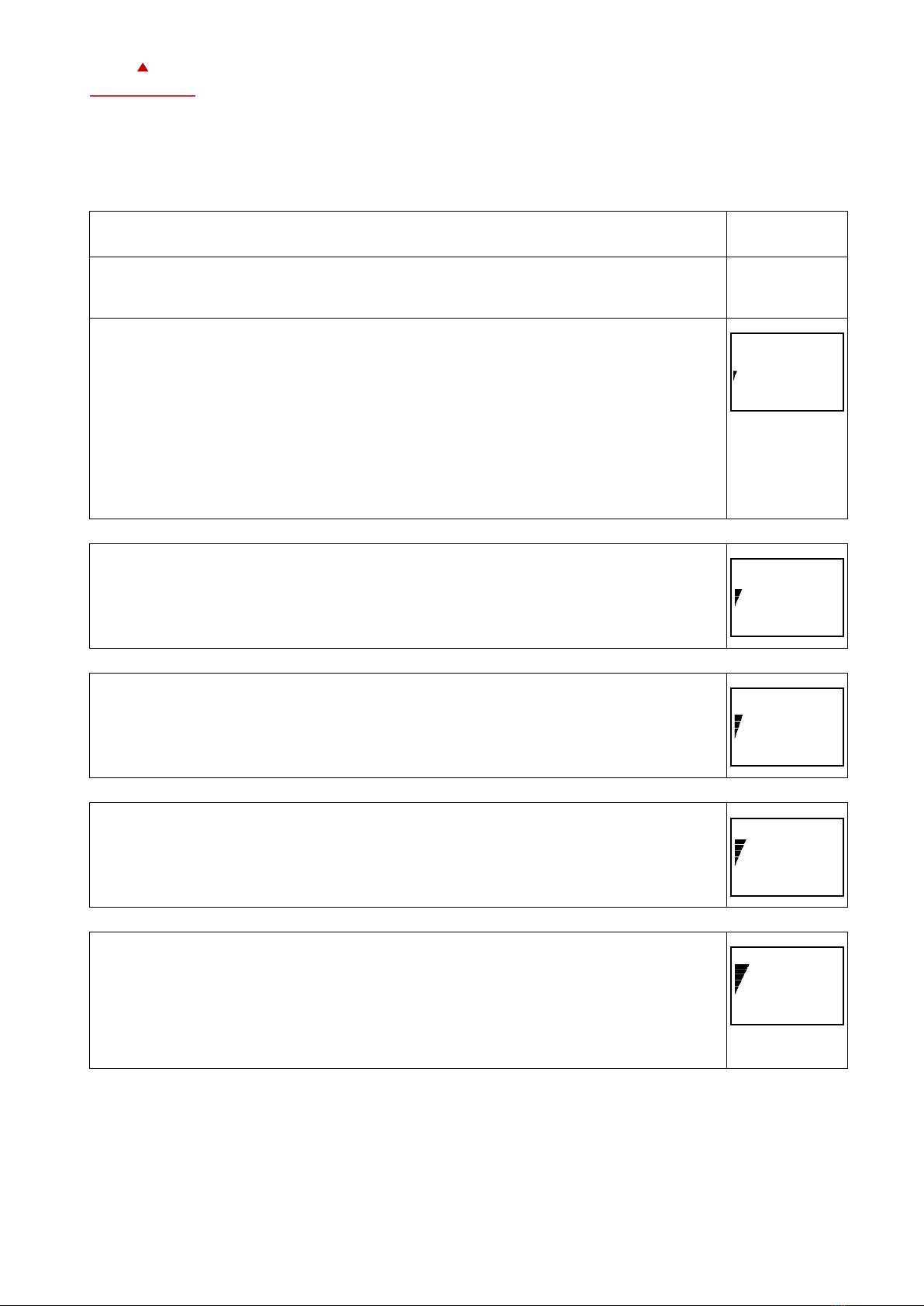
Display of control loop
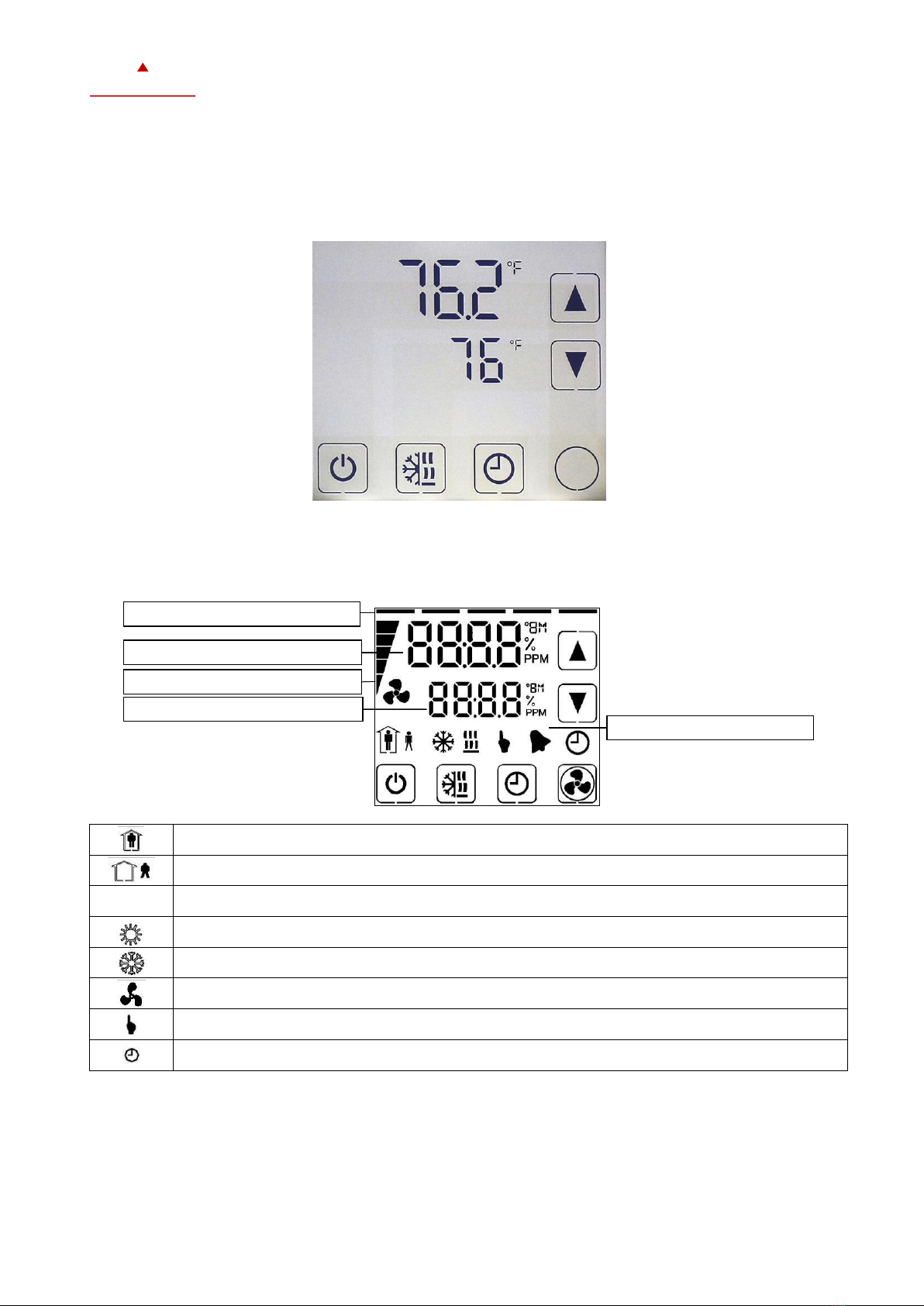
•Active when setpoint is changed. Large digits indicate the input value. Small digits indicate the setpoint. Horizontal
bars at the top left indicate which control loop are displayed.
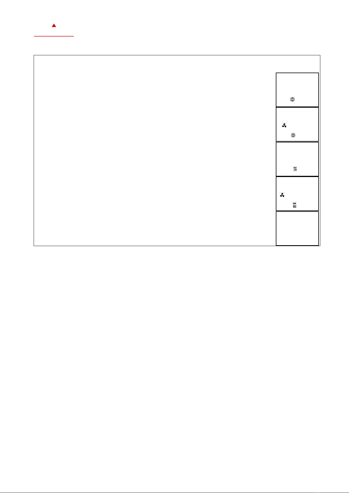
Override of secondary set point in cascade control
•With cascade control, manual override of the secondary circuit can be activated. This is defined by the technician in
the controller settings.
•This allows the user to override the primary circuit (e.g. with VAV) and manually select the setpoint of the
secondary circuit (control is then switched to constant volume flow mode). This function is helpful when tuning the
VAV system. While the secondary loop is displayed, press UP/ DOWN button to change the setpoint. The hand
symbol appears. Change the setpoint again to cancel the cascade override. The hand symbol disappears.
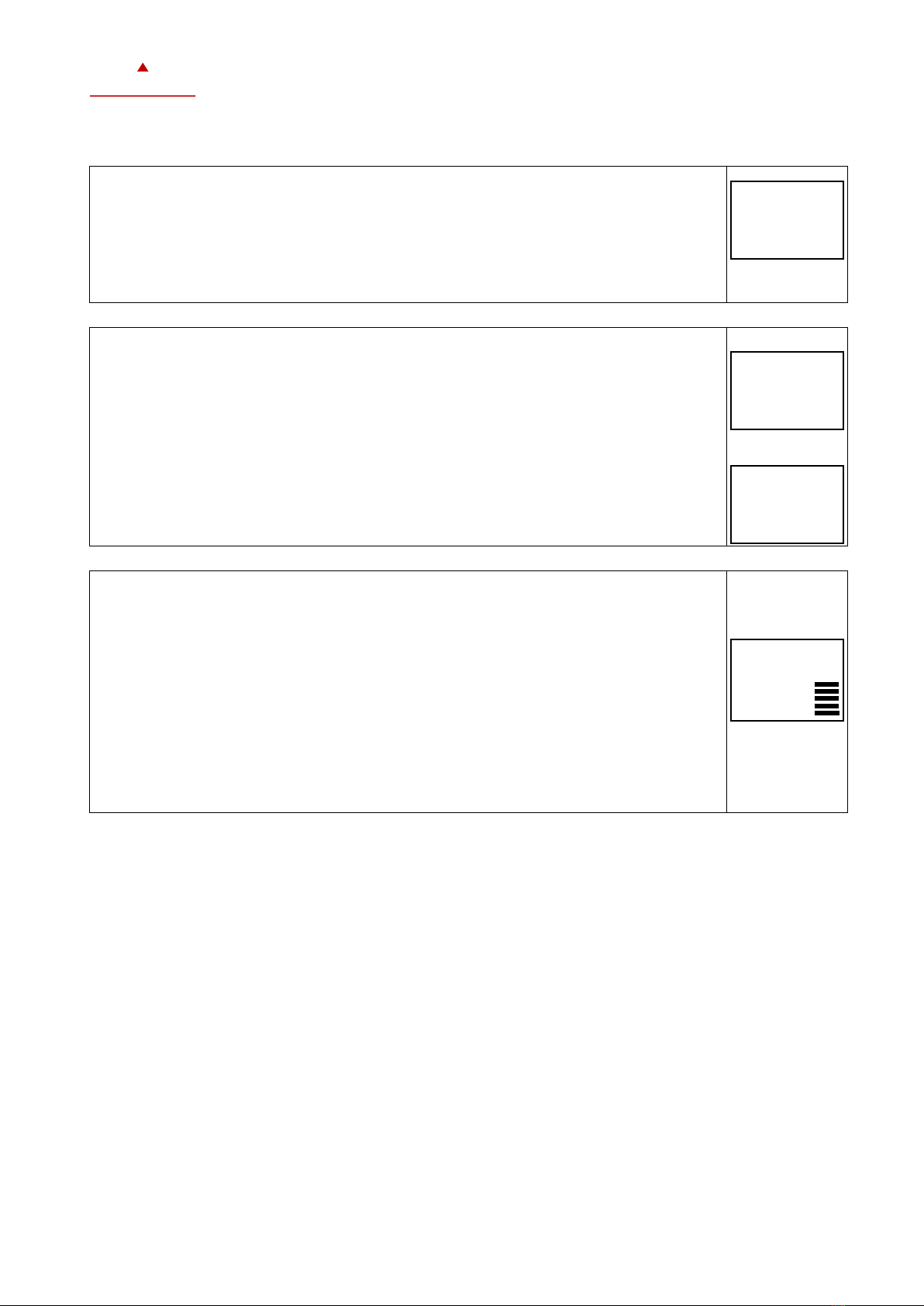
Manual Mode
•The hand symbol is displayed during a pending delay. For example, if a start-up delay is active. The controller
remains switched off and displays the hand symbol until the delay has elapsed. Then the controller switches on
and the hand symbol goes out.
Status-LED
•Most devices have a status LED. The status LED is defined in the product data sheet. In normal operation, the LED
flashes briefly once every 5 seconds. The LED flashes every second when an alarm or fault condition is present.
Power Failure
•All device settings and time programs are stored and do not need to be reprogrammed. The switch-on behaviour on
return of the power supply is set by the technician.
•If a real time clock is available, it will continue to run for at least 48 hours (after switching on for 10 hours). The
time does not have to be entered again when the power supply returns.
Error Messages
Err1: Communication error
Err2: Internal error: Firmware version of the memory does not match firmware.
Err3: Timer error: Set time and acknowledge error. If an error occurs again at a previously set time, the watch is
faulty. Time switching functions are not guaranteed in this case.
Err4: Configuration error: An assigned input is not activated or has failed. Check all settings and ensure that all
inputs used are activated and functional.
Err5: Copy error: Communication error with external memory AEC-PM1 or AEC-PM2.
Err6: Copy error: Checksums of the data record are incorrect. The data record is invalid.

X2-OPERATING MANUAL
WITH TOUCH SCREEN
Doc: 70-00-0741, Serie X2, 20190213 © Vector Controls GmbH, Schweiz Page 5
subjects to alteration www.vectorcontrols.com
VECTOR
Extended operating level
Timer Switch
Note Accuracy
Warning: The TCX2-40863 and devices with a -C addition have a real-time clock. This clock is accurate to two seconds a
day. Other TCX2 series devices calculate the time based on the processor's internal clock speed. This time source is
accurate to approx. 2 minutes per day. If the controller uses its time program functions, it is therefore necessary to
synchronize the time of these controllers at least every 24 hours with an exact time base.
Time Programs
Up to 12 time and weekday programs or annual holidays can be programmed (Pr01 to Pr12). Schedules can change the
operating mode of the controller (on, off, busy, unoccupied), change the fan status, position an output directly or
change a setpoint.
A flashing clock indicates that the time has not been set or that the terminal has been without power for more than 48
hours. The time must be set for the schedules to work.
The summer/winter time changeover can be activated by the technician via user parameters.
1. Setting the Time
1.1. Press CLOCK button longer than 2 sec.
➔SEL and Date or Time (alternately) is displayed.
1.2. Press RIGHT button briefly to change the time and date:
minutes flashes: UP/ DOWN button for adjustment, RIGHT key for storage
Hours flashes: UP/ DOWN button for adjustment, RIGHT key for storage
DAY1 flashes: UP/ DOWN button for adjustment, RIGHT key for saving the day of
the week
Day of the month flashes: UP/ DOWN button for adjustment, RIGHT key for
storage
Month flashes: UP/ DOWN button for adjustment, RIGHT key for storage
Year flashes: UP/ DOWN button for adjustment, RIGHT key for storage
1.3. Press LEFT button (1x) for back.
2. Activating or deactivating the time programs
2.1. Press CLOCK button longer than 2 sec.
➔SEL and Date or Time (alternately) is displayed.
See Picture
1.1.
2.2. Press UP button
➔PRO and SEL is displayed.
2.3. Press RIGHT button:
Schedule status indicates whether it is OFF or ON
When status is ON = in the display. Press the RIGHT button to change the status.
2.4. Press LEFT button (1x) for back to the submenu.
ON
Pro
OFF
Pro
SEL
Pro
SEL
2006
SEL
day7
SEL
12 30
This manual suits for next models
11
Table of contents
Other Vector Industrial Equipment manuals