CHWS Propak Thermal Series Instruction Manual

PROPAK THERMAL SERIES
Installation Manual
Operation & Maintenance Manual

2| OPERATION & MAINTENANCE MANUAL
Principal
CHWS Propak is a compact and highly
ecient DHW production system
incorporating a gasketed plate heat
exchanger, electrically actuated 3-port
control valve, safety relief valve, A-rated
ERP variable speed primary pumps with a
secondary pump supplied on the Propak
plus units.
The unit is complete with a full PID
controller and PT100 temperature sensor.
The motorized 3-port valve allows high
speed adjustment of the primary heat
input to match changes in secondary hot
water demand. The design maintains the
outlet temperature at the set point (default
60ºC) and consequently reduces the risk of
legionnaires disease within the system.
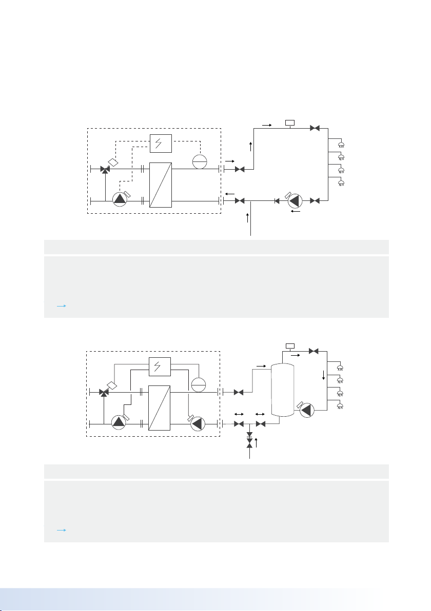
See schematic layout:
A) Propak Thermal Instantaneous
B) Propak Thermal Plus Semi-Instantaneous
Secondary Inlet
Secondary Outlet
Primary Inlet
Primary Outlet
Key
1
2
3
4
3
OPERATION & MAINTENANCE MANUAL |
Instantaneous Applications
1
2
C
E
F
G
3
LK
J
4
H
B
TT
1
A
D
AAV
1
2
C
E
G
G
3
J
G
B
TT
1
A
N
H
D
AAV
G
G
K
4
1
2
C
E
F
G
3
LK
J
4
H
B
TT
1
A
D
AAV
1
2
C
E
G
G
3
J
G
B
TT
1
A
N
H
D
AAV
G
G
K
4
Semi-Instantaneous Applications
Primary ow
Primary return
Cold mains feed
Secondary ow
DHW Flow direction
Key
1
2
3
4
Isolation valve
Isolation valve
Isolation valve
Secondary return pump
Automatic air vent
G
H
J
K
AAV
Heat exchanger
Primary pump
Control valve
Control panel
Temperature sensor
Isolation valve
A
B
C
D
E
F
Semi-Instantaneous Applications
Semi-Instantaneous Applications
Primary ow
Primary return
Cold mains feed
Secondary ow
DHW Flow direction
Key
1
2
3
4
Isolation valve
Buer vessel
Secondary return pump
Non-return valve
Automatic air vent
G
H
J
K
AAV
Heat exchanger
Primary pump
Control valve
Control panel
Temperature sensor
Secondary shunt pump
A
B
C
D
E
F
4| OPERATION & MAINTENANCE MANUAL
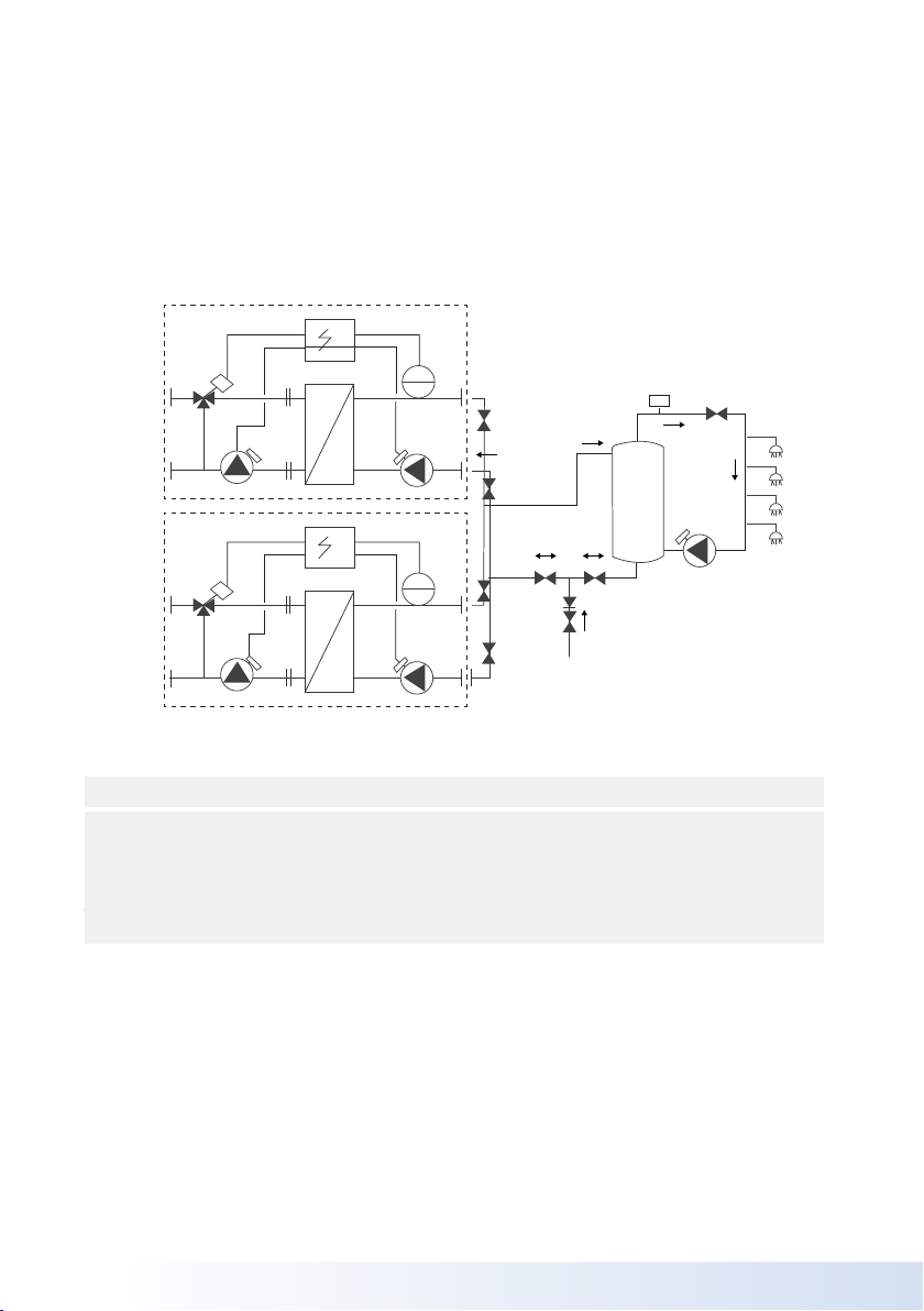
Semi-Instantaneous Applications Duty-Duty
1
2
C
E
4
G
4
J
H
J
5
G
B
TT
1
A
D
AAV
1
2
C
E
G
G
3
B
TT
1
A
F
G
D
G
G
K
4
5
G
5
F
The Propak & Propak Plus come fully
assembled and are ready to operate. All
ancilliaries are mounted on the unit using
stainless steel piping. All Propak & Propak
Plus units are tested hydraulically and
electrically at the factory.
Semi-Instantaneous Applications
Primary ow
Primary return
Cold mains feed
Building service ow
Building service return
Key
1
2
3
4
5
Isolation valve
Buer vessel
Secondary return pump
Non-return valve
Automatic air vent
G
H
J
K
AAV
Heat exchanger
Primary pump
Control valve
Control panel
Temperature sensor
Secondary shunt pump
A
B
C
D
E
F

5
OPERATION & MAINTENANCE MANUAL |
Installation
All installation work must be undertaken by a
qualied and competent person.
The heat exchangers must be installed in
accordance with the following requirements:
The current Building Regulation
The Water Supply (Water Fittings)
Regulations 1999
Additionally, installation should be
performed in accordance with all relevant
requirements of the Local Authority and
recommendations of the British Standards
and Codes of Practice:
BS EN 806 Parts 1-5: 2000 – 2012
Specication for design, installation, testing
and maintenance of services supplying
water for domestic use within buildings and
their curtilages. This standard supersedes
the following British Standards and Codes
of Practice: CP99, CP310, CP324, CP202,
CP342 Part 2, Centralised Hot Water Supply.
BS 7206:1990 Specication for unvented
hot water storage units and packages.
•
•

6| OPERATION & MAINTENANCE MANUAL
Unloading
The Propak unit comes assembled on a
mild steel skid which should be mounted
on prepared foundations that are level and
suitable for the size and weight of the unit.
The unloading of the equipment is the
responsibility of the recipient and should be
carried out with care to avoid damage to the
unit.
Use web slings (no metal chains). Insert
them in the designated notches on the
head and follower.
When moving and handling the heat
exchanger, make sure that it is properly
supported and secured as its high
centre of gravity may cause it to tip over.
Never lift the unit by its guide rails,
compression bolts or pipework.
Shield the plates, pumps, valves &
controller from impacts as they could
cause irreparable damage.
Pipework
Make sure that the pipework connections
are aligned and correctly spaced before
connecting. See that the weight of the
pipework is taken by external supports and
not by the Propak. Allowances should be
made for expansion of the pipes either by
suitable bends or exible joints. Threaded
connections may be sealed with PTFE tape.
Flanged connections should be sealed with
a suitable gasket and sealing agent.
Venting Vent valves must be tted at the
highest point in the connecting pipework to
enable purging air for initial operation.
Purge all pump bodies, see the pump
manufacturers instructions supplied. Flush
out the system pipework before installing
to remove any foreign matter which may
impact on the valve and pump operation.
Filling
Before lling the system check that the
drain valve is closed and all air vents are
open. Slowly ll both sides of the system
with water. Caution:- Do not ll the system
too quickly otherwise pockets of air may
become trapped. Once lled purge air at
high points and purge all the pump bodies.
Switch the power on to the unit and check
the controller settings and enable the
required functions.
(see further set up instructions)
The heat exchanger and its components
must never be used for purposes other than
those for which they were initially designed.
Electrical connection
Connect a single phase 230V 50Hz supply
to the Mains Input terminals. (See electrical
wiring diagrams section). If the unit is to
be controlled remotely connect the remote
control switch or contacts to the Remote
enable terminals.
•
•
•
•

7
OPERATION & MAINTENANCE MANUAL |
Commissioning
Before installation this manual must be read.
The controller has been set at the factory
with default parameters. If any function
needs tuning, values can be changed
with reference to the instruction manual
for parameter setting. Initially, the
commissioning process should be carried
out with the factory settings.
Contact us to arrange a commissioning
engineer’s visit.
Maintenance and repairs
The frequency of the inspections depends
on the water hardness, temperature and
ow rate. CHWS can oer a low cost annual
service contract. Please contact us for more
information.
We recommend the following periodical
checks:
Weekly inspection to check for leaks
from pipes or components.
Weekly inspection to make sure that
the operation control systems is stable
and that the temperature does not
uctuate. Temperature hunting causes
unnecessary wear of valves, actuators.
The control box does not require any
specic maintenance; annually check
the electrical connections tightening.
Annually check the control valve that
no leaks are detected. Lime scaling on
the connected devices. Scaling of the
secondary side will be evidenced by:
a high pressure drop on the secondary
side of the exchanger, improper
temperature range on the secondary
side of the exchanger, low temperature
dierence between inlet and outlet on the
primary side of the exchanger when the
control valve is fully open.
Only replace any defective parts with the
original spare parts. Please contact CHWS
for spare parts. Maintenance work must be
carried out by a qualied and authorized
technician.
Hazard of electrical shock or scalding.
Before carrying out any works
disconnect power supplies.
With high primary and secondary
temperatures there is a risk of scalding.
All pipework must be cool before
carrying out work.
•
•
•
•
•
•
•
•

8| OPERATION & MAINTENANCE MANUAL
Warranty
Our equipment comes with a 24-month
warranty from the date of shipment and
is subject to commissioning by CHWS.
The manufacturer’s liability is limited to
the replacement of any damaged parts
that are not repairable. No other nancial
reimbursement may be claimed in any case
under the warranty. The fault and probable
cause must be advised to CHWS before
any remedial works is undertaken. The
defective part should then be returned to
our Head Oce for assessment unless prior
arrangement to proceed otherwise has been
supplied from CHWS. Assessment of the
defective part will conclude whether or not
the terms of the warranty apply.
Exclusions:
Non-compliance with the guidelines for
installation, conguration and maintenance:
Over pressures, water-hammer, scaling,
noncompliant water quality.
Also excluded from the warranty:
Fitting costs, retting costs, packaging,
transport, and any accessories or
equipment not supplied
by CHWS, which will only be covered by
any warranties issued by said third-party
manufacturers.
Any damage caused by connection
errors, insucient protection,
misapplication or faulty or careless
operations.
Equipment disassembled or repaired by
any other party than CHWS or TPS.
Non-payment for goods will lead to all
operational warranties covering the delivered
equipment being terminated.
•
•
•
9
OPERATION & MAINTENANCE MANUAL |
Operation & Maintenance
Manual
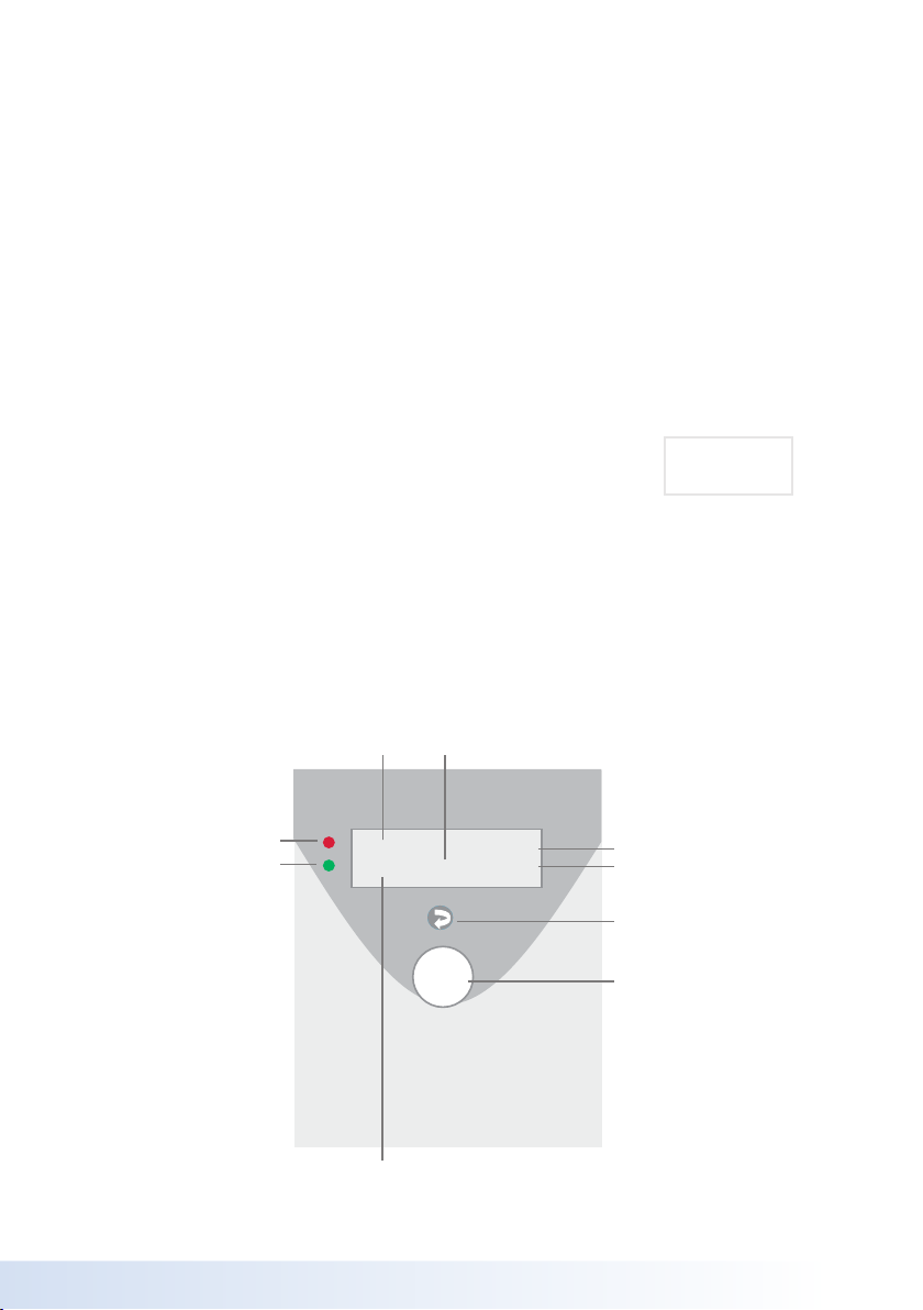
Control box
Display
The control unit allows the display of
operating conditions: factory settings or
programmed settings and indication of
errors – it also enables users to respond to
changes in basic and advanced settings.
The Propak Thermal comes with a range
of factory pre set parameters, these can
be changed by adjustments in the basic
parameter setting mode or the advanced
programming mode.
2
Time
Control Dial
Percentage open position
of 3 port control valve
Date
Measured temperature
Red LED (Defect)
Green LED (Operational)
Return Button
Temperature setpoint
10H15 02/03/2014
65.0ºC Tc: 65 100%
Navigation
To enter the programming menu, press the
and hold the control Dial for 5 seconds and
then release.
The screen displays:
All consolidation and modication of
program settings are achieved using the
Control Dial.
To enter a program or to consent a
parameter, press the Control Dial.
To exit a program step, press the return
button.
MENU ECS
Selection PROG
•
•
•

10 | OPERATION & MAINTENANCE MANUAL
Simple and advanced settings
The factory settings can be modied in basic
and advanced settings.
List of simple settings
Menu Factory settings Setting mode
Day setting
• DHW temperature setting
• Adjustment Single or Daily
Temperature setpoint
Starting time
Basic and
Advanced
conguration
mode
Night setpoint
• DHW temperature setting
• Adjustment Single or Daily
Temperature setpoint
Starting time
Basic and
Advanced
conguration
mode
Setting the time
• Setting the time
• Setting the date
• Setting the day of the week
Basic and
Advanced
conguration
mode

11
OPERATION & MAINTENANCE MANUAL |
Details of basic and advanced settings
DAY
SETPOINT
Factory
settings
Basic and Advanced
conguration mode
Settings
on site Index
Temp: ºC 58ºC 0ºC - 99ºC DHW temperature
setting -100
Daily No Yes - No Daily setting - 101
Monday: ºC 58ºC 0ºC - 99ºC
DHW
temperature
setting and daily
starting time
-102
Monday: hrs 6:00 0:00 - 23:00 - 103
Tuesday: ºC 58ºC 0ºC - 99ºC - 104
Tuesday: hrs 6:00 0:00 - 23:00 - 105
Wednesday: ºC 58ºC 0ºC - 99ºC - 106
Wednesday: hrs 6:00 0:00 - 23:00 - 107
Thursday: ºC 58ºC 0ºC - 99ºC - 108
Thursday: hrs 6:00 0:00 - 23:00 - 109
Friday: ºC 58ºC 0ºC - 99ºC - 110
Friday: hrs 6:00 0:00 - 23:00 - 111
Saturday: ºC 58ºC 0ºC - 99ºC - 112
Saturday: hrs 6:00 0:00 - 23:00 - 113
Sunday: ºC 58ºC 0ºC - 99ºC - 114
Sunday: hrs 6:00 0:00 - 23:00 - 115
Administrator mode can be accessed from
Operator mode via the last sub-menu of the
setting menu.

12 | OPERATION & MAINTENANCE MANUAL
Details of basic and advanced settings
NIGHT
SETPOINT
Factory
settings
Basic and Advanced
conguration mode
Settings
on site Index
Temp: ºC 58ºC 0ºC - 99ºC DHW temperature
setting - 130
Daily No Yes - No Daily setting - 131
Monday: ºC 58ºC 0ºC - 99ºC
DHW
temperature
setting and daily
starting time
- 132
Monday: hrs 22:00 1:00 - 23:00 - 133
Tuesday: ºC 58ºC 0ºC - 99ºC - 134
Tuesday: hrs 22:00 1:00 - 23:00 - 135
Wednesday: ºC 58ºC 0ºC - 99ºC - 136
Wednesday: hrs 22:00 1:00 - 23:00 - 137
Thursday: ºC 58ºC 0ºC - 99ºC - 138
Thursday: hrs 22:00 1:00 - 23:00 - 139
Friday: ºC 58ºC 0ºC - 99ºC - 140
Friday: hrs 22:00 1:00 - 23:00 - 141
Saturday: ºC 58ºC 0ºC - 99ºC - 142
Saturday: hrs 22:00 1:00 - 23:00 - 143
Sunday: ºC 58ºC 0ºC - 99ºC - 144
Sunday: hrs 22:00 1:00 - 23:00 - 145

13
OPERATION & MAINTENANCE MANUAL |
INSTAL. TYPE Factory
settings
Advanced
conguration mode
Settings
on site Index
(following
product
conguration)
Simple Inst.
Double Inst.
Semi - Inst. S-S
Semi - Inst. D-S
Semi - Inst. D-D
Installation
type -200
LEGIONELLA Factory
settings
Advanced
conguration mode
Settings
on site Index
Active: No Yes - No Activating
treatment -240
Day: Wednesday - Date - 241
Starting hour: hrs 3h 0h - 23h Time -242
Duration cycle:
min 20 min 1 min - 99 min Duration - 243
Second sensor: No Yes - No Second sensor
option -244
Temp. Settings:
ºC 80 ºC 0ºC - 99ºC Treatment
temperature -245
Neut. Legio AL:
min 3 min 0 min - 9 min Alarm delay
after completion -246
In compliance with the regulations
(preventing risk of burn), all safety measures
should be taken to ensure that during the
water treatment, water temperature does not
exceed 60ºC at the taps.

14 | OPERATION & MAINTENANCE MANUAL
ALARM AND
STEP
Factory
settings
Advanced
conguration mode
Settings
on site Index
Turbo: Tc- ºC 10ºC 0ºC - 99ºC T to set o turbo -260
Al High: Tc+ ºC 15ºC 0ºC - 99ºC T to set o alarm -261
Al low: Tc- ºC 15ºC 0ºC - 99ºC High or low - 262
High abs AL: ºC 80ºC 0ºC - 99ºC Absolute alarm - 263
Low abs AL: ºC 40ºC 0ºC - 99ºC High or low - 264
Temp2Max Out: No Yes - No Activate the
limitation and -268
Temp2Max: ºC 80ºC 10ºC - 99ºC Max output
temperature - 269
Hysteresis: 0.2 0.1 - 9.9 Hysteresis defects -270
Check mes: No Yes - No Return signal of the
opening of the 3WV -271
Di mes: % 10% 1% - 99% Measure dierence
at opening -272
Open Valve: % 10% 0% - 99% Opening 3WV - 273
Auto reset: Ye s Yes - No Automatic reset - 299

15
OPERATION & MAINTENANCE MANUAL |
OPERATING
COUNTER
Factory
settings
Advanced
conguration mode
Settings
on site Index
Pump 1: hrs Oh Oh - 99999h Time duration
of each pump
operation in
hours
- 350
Pump 2: hrs Oh Oh - 99999h - 351
Pump 3: hrs Oh Oh - 99999h - 352
Pump 4: hrs Oh Oh - 99999h - 353
DISPLAY
DEFECT RELAY
Factory
settings
Advanced
conguration mode
Settings
on site Index
AL high Temp: 10 - 2
Relay / defects
assignment
- 300
AL low Temp: 10 - 2 - 301
AL pump 1: 20 - 2 - 302
AL pump 2: 20 - 2 - 303
AL pump 3: 20 - 2 - 304
AL pump 4: 20 - 2 - 305
AL Input Ana 1: 20 - 2 - 306
AL Input Ana 2: 20 - 2 - 307
AL Input Ana 3: 20 - 2 - 308
AL sensor: 20 - 2 - 313
HISTORY OF
DEFECTS List of defect history (max 20) Index
340

16 | OPERATION & MAINTENANCE MANUAL
INPUTS /
OUTPUTS
Factory
settings
Advanced
conguration mode
Settings
on site Index
Analog Input 1
Type: Pt100
PT100
0-10v / 4-20mA
and
shift of input
signal
0-10v / 4-20mA
Output signal
- 370
Oset: 0-10 to 100 - 371
Low scale: 0-9.9 to 9.9 - 372
High scale: 100 -10 to 100 - 373
Analog Input 2
Type: Pt100 - 380
Oset: 0-10 to 100 - 381
Low scale: 0-9.9 to 9.9 - 382
High scale: 100 -10 to 100 - 383
Analog Input 3
Type: 0-10V - 390
Oset: 0-10 to 10 - 391
Low scale: 0-9.9 to 9.9 - 392
High scale: 100 -10 to 100 - 393
Analog Input 1
Type: 4-20mA - 400
Oset: 0.0 -100 to 100 - 401
Analog Input 2
Type: 4-20mA - 405
Oset: 0.0 -100 to 100 - 406

17
OPERATION & MAINTENANCE MANUAL |
PID
CONTROLLER
Factory
settings
Advanced
conguration mode
Settings
on site Index
Prop band: 8.0 0 - 100 Proportional
band -420
Derivated: % 40.0% 0.0% - 100% Derivative time - 421
Integral: 0.2 0 - 100 Integral time - 422
Dead band: 0.0 0 - 20 Dead band - 423
3WW opening
time: secs 35s 0s - 255s
Time duration
of the 3 way
valve
-424
Output max: % 100% 25% - 100% Opening limite
of the valve -425
Cold: No Yes - No Cold option -426
PP/3WV: % 40.0% 0.0% - 99%
Shift of
pump/3WV
signal
-427
Taking into account the parameters of PID
occurs after a reboot of the box.
PROG.
SELECTION
Factory
settings Advanced conguration mode Index
DHW DHW / GMP*/ aquaAirless* Application type 439
* unavailable

18 | OPERATION & MAINTENANCE MANUAL
FORCED START Factory
settings
Advanced
conguration mode
Settings
on site Index
Pump 1: No Yes - No
Forced start
for
each pump
440
Pump 2: No Yes - No - 441
Pump 3: No Yes - No - 442
Pump 4: No Yes - No - 443
Three-way-valve 3P
Forced: No Yes - No Forced start - 445
No change: +/-% 5% 0% - 50% No settings -446
Analog Output 1
Forced: No Yes - No Forced start - 450
Value: % 50% 0% - 100% No settings -451
Analog Output 2
Forced: No Yes - No Forced start - 455
Value: % 50% 0% - 100% % of cancelling - 456
Cancel: No Yes - No value 459

19
OPERATION & MAINTENANCE MANUAL |
SET THE TIME Factory
settings
Advanced
conguration mode
Settings
on site Index
Hour: hrs 0h00 - 23h59 Hour - 480
Date: - - / - - / - - Date - 481
Day: - - - - - - day Day of the week - 482
FACTORY
SETTINGS
Factory
settings
Advanced
conguration mode
Settings
on site Index
Reset: No Yes - No Reset to factory
settings - 479
MODBUS
RTU / RS485
Factory
settings
Advanced
conguration mode
Settings
on site Index
Address: 11 - 128 Modbus
address -460
Bauds: 9600 4800 - 9600 - 19200 Communication
speed -461
Parity: None None / Even / Odd Parity - 463
Num Stop Bit: 11 - 2 output RS 485 - 464

20 | OPERATION & MAINTENANCE MANUAL
ADMINISTRATOR
MODE
Factory
settings
Basic and Advanced
conguration mode
Settings
on site Index
Administrator
mode: No Yes - No Access admin.
mode - 899
Index Modbus Variables
1Measure
2 Set point
3 Output
4Current defects
5 Word State 1
6In Ana1
7In Ana2
8In Ana3
9 Out An1
10 Out An2
11 In Digital
12 In Ipso
13 Out Relay
14 Current step
15 Bit Defect 1
16 Bit Defect 2
This manual suits for next models
12
Table of contents
Other CHWS Industrial Equipment manuals

Popular Industrial Equipment manuals by other brands

ROBOD
ROBOD MULTICHRON PRO VIS Usage and maintenance manual

Halma
Halma Crowcon Xgard S011843 Installation, operating and maintenance instructions

Siemens
Siemens SIWAREX R operating instructions

Schmalz
Schmalz SCPSi-L operating instructions

X-Rite
X-Rite PANTONE Judge QC Operation manual

Phuel
Phuel 145-2884-HV0 user manual

Pasco Scientific
Pasco Scientific WA-9401 Instruction manual and experiment guide

ATS
ATS Pressure Aging Vessel 4 instruction manual

Schmalz
Schmalz FMP-SVK Series operating instructions

Rohloff
Rohloff SPEEDHUB 500/14 Mounting

MBO
MBO SAP 46 L operating manual

Buhler
Buhler GAS 222.10 Assembly, installation and operation instructions


