CIAM 900 Series Mounting instructions
E
CIAM spa - Viale dei Pini, 120
06081 Petrignano d’Assisi Perugia
ITALY
© CiamGroup
http://www.ciamgroup.it
e-mail: [email protected]
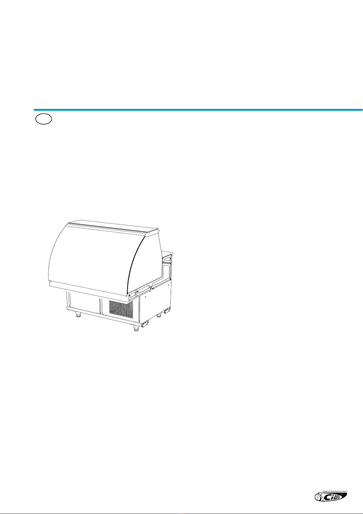
Refrigerated Showcases
SERIES 750-900
MAINTENANCE
AND USER MANUAL

3
1. GENERAL INFORMATION
This documentation is edited in compliance with that de ned in point 1.7.2 of Directive EC 37/98 concerning the
approximation of laws of the Member States relating to machinery.
The content of this manual is of a strictly technical nature and is the property of CIAM Spa, it is therefore forbidden
to reproduce, reveal or modify, partially or completely, its content without written authorisation.
Any infringement will be legally pursued.
1.1 Warnings for the purchaser
The manual, as well as the EC certi cate of conformity, is an integrating part of the machine and must accompany it
always, whether it is transferred or resold. It is up to the user to keep all the documentation intact for consultation,
during the machine entire life-span.
In case of loss or destruction, it is possible to request a copy from CIAM Spa specifying the exact model, serial
number and year of manufacture.
The manual re ects the technical state at the time of supply. The writing company reserves the right to make any
amendments to its products it sees t, without having to update manuals and plants relating to previous production
batches.
The manufacturing company declines any responsibility for production anomalies and damages caused by the
machine to things, persons and animals occurred in the following cases:
• Improper use of the plant or use on behalf of unsuitable or unauthorised personnel
• Power supply defects
• Insuf cient or lack of periodic maintenance
• Amendments or interventions not agreed and authorised by the manufacturer
• Use of unoriginal spare parts or not speci c for the model
• The total or partial non compliance with these instructions
The responsibility for applying the safety prescriptions reported below is of the technical personnel responsible for
the activities on the machine, who must ascertain that the authorised personnel:
• is trained to carry out the requested activity
• is aware of and scrupulously observes the prescriptions contained in this document
• is aware of and applies the general safety regulations to the machine.
The non compliance with the safety regulations can cause injuries to personnel and damage the components and
control unit of the machine.
The comprehensive reading of this manual cannot, in any case, replace an adequate experience of the operators.
The user can, at any time, contact the dealer to request information additional to that contained herewith, as well
as signal any improvement proposals.
4
1.2 Introduction
The CIAM group has always used top quality materials and their introduction in the company, their storage and
their production use is constantly controlled in order to guarantee there are no damages, deteriorations and
malfunctionings.
All the constructive elements have been designed and built to guarantee a high safety and reliability standard.
All the display cabinets are submitted to rigid tests before being delivered. However, a good performance in time of
the purchased product, depends on the correct use and an adequate maintenance.
We therefore invite you to scrupulously read this manual containing the necessary indications to maintain the
aesthetic and functioning features of your display cabinet unaltered.
NOTE
IN ORDER NOT TO COMPROMISE THE FUNCTIONING AND SAFETY OF THE MACHINE, INSTALLATION
AND PARTICULARLY COMPLEX MAINTENANCE ARE NOT DOCUMENTED IN THIS MANUAL AND ARE
CARRIED OUT BY THE WRITING COMPANY SPECIALISED TECHNICIANS
The use and maintenance manual contains the necessary information to comprehend the functioning modalities
of the machine and the correct use of the same, in particular: the technical description of the various functioning
groups, appliances and safety systems, functioning, use of instruments and interpretation of any diagnostic signals,
main procedures and information relating to routine maintenance interventions.
For the correct use of the machine it is necessary that the work environment is in compliance with the safety and
hygiene regulations in force.
!WARNING
BEFORE USING THE MACHINE, THE INSTALLERS AND USERS MUST READ AND COMPREHEND ALL
THE INSTRUCTIONS CONTAINED HEREWITH.
1.3 Manufacturer’s address
INSTRUCTIONS FOR REQUESTING INTERVENTIONS
For assistance, the user must contact the dealer from whom he has purchased the appliance. The writing company is
always at the disposal of the Client for any requests of information or clarication relating to the use, maintenance,
installation, etc., via e-mail address: [email protected].
CIAM spa
Head ofce and establishment:
06083 Bastia Umbra (PG) Italy
Viale Europa, 120
Tel. (+39) 075 80161 Fax. (+39) 075 8016215
http://www.ciamgroup.it e-mail: [email protected]

5
1.4 Safety regulations in the manual
The purpose of the prescriptions, indications, regulations and respective safety notes described in the various
chapters of the manual, is that to dene a series of behaviours and obligations to be complied with when carrying out
the various activities, in order to operate in safe conditions for personnel, appliance and surrounding environment.
The reported safety regulations are aimed at the authorised and trained personnel commissioned to carry out the
various activities and operations of:
• transport
• installation
• functioning
• handling use
• maintenance
• cleaning
• decommissioning and dismantling which constitute the only use modalities provided for the machine in
question.
!ATTENTION
THE COMPREHENSIVE READING OF THIS MANUAL CANNOT, IN ANY CASE, REPLACE AN ADEQUATE
EXPERIENCE OF THE USER, THEREFORE CONSTITUTING ONLY A USEFUL REMINDER OF THE TECH-
NICAL FEATURES AND THE MAIN OPERATIONS TO BE FULFILLED.
1.5 Symbols used
Certain symbols are used in the manual to recall the readers’ attention and highlight certain particularly important
aspects of the treatment.
The following table describes the meaning of the different symbols used.
SYMBOL MEANING NOTES
Danger Indicates a danger with risk of injury, even death, for the user.
Pay maximum attention to the blocks of text indicated by this symbol.
!Attention Represents a warning of possible deterioration or damage to the machine, appliance or
another personal object of the user.
Pay maximum attention to the blocks of text indicated by this symbol.
Warning
Note
Indicates a warning or a note on the key functions or useful information.
Pay maximum attention to the blocks of text indicated by this symbol.
Supplementary
information
The blocks of text which contain complementary information are introduced by this
symbol.
This information has no direct relation with the description of a function or the development
of a procedure.
They can be cross-referenced to other complementary documentation, such as attached
use instructions manuals, technical documents or to other sections of this manual.
Avoid damaging
the material
Indication relating to a strong risk of damaging a piece, for example by using a wrong tool
or mounting following an incorrect procedure.
Special tool Indicates that the use of a tool or special appliance is effectively necessary.
Visual observation Indicates to the reader that he must proceed to a visual observation. This symbol is also
found in the use instructions. It is requested that the user reads a measuring value, checks
a signal, etc.
Auditory
observation
Indicates to the reader that he must proceed to an auditory observation. This symbol is also
found in the use instructions. It is requested that the user listens to a functioning noise.
6
2. DIMENSIONAL SIZES AND TECHNICAL SPECIFICATIONS
2.1 USE DESTINATION
This refrigerating equipment is exclusively enabled for the display and sale of confectionery and delicatessen
products. It is also possible to display small sized packaged dairy products and sliced packaged cold cuts, positioned
in such a way not to exceed the load limits indicated in the manual.
The manufacturer does not answer for damages caused to things, persons or the same equipment due to product
preservation different to that speci ed above.
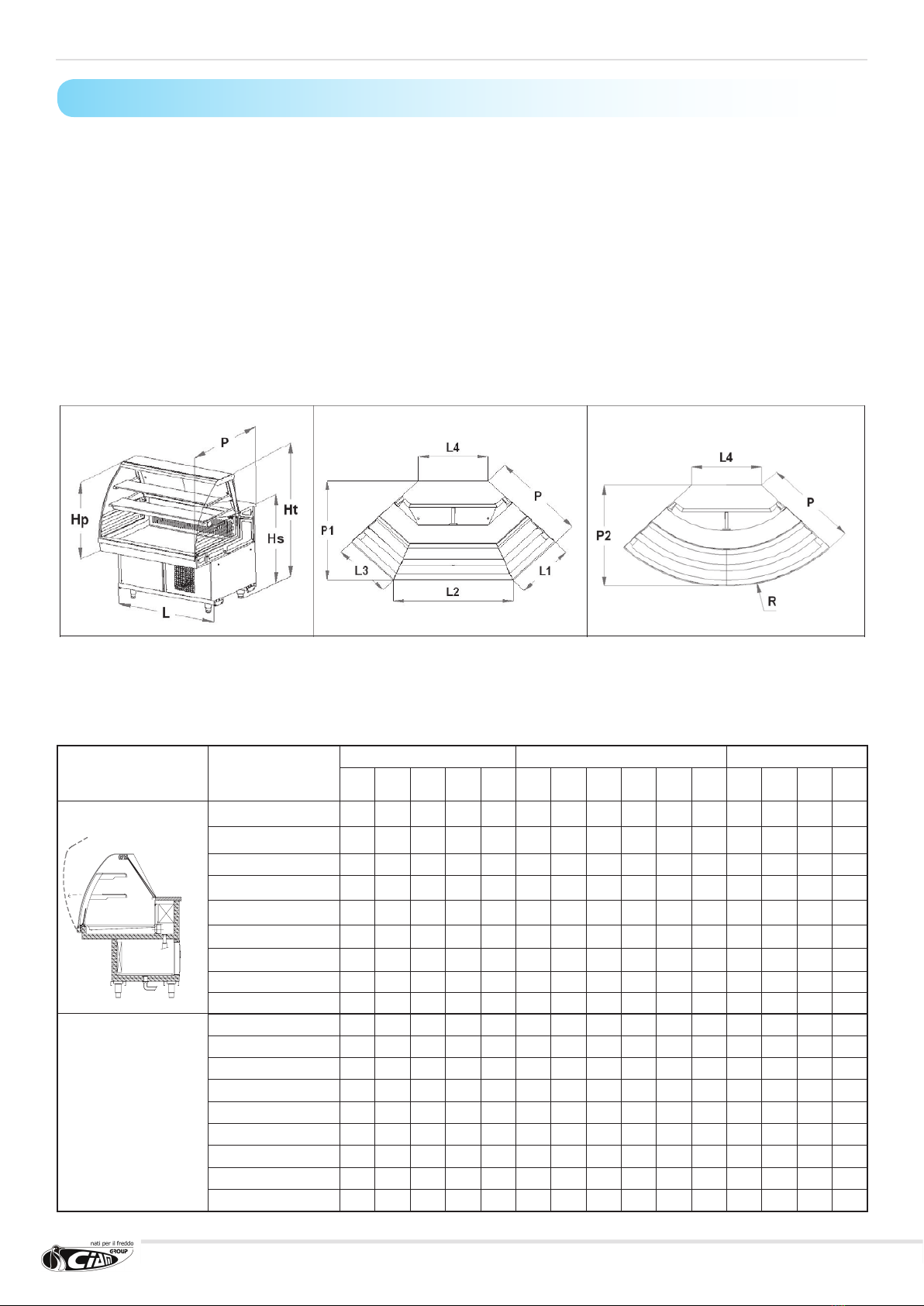
2.2 Equipment dimensions
2.2.1 Series 900
The sizes highlighted in the following two paragraphs represent, respectively: Hp=plate height – Hs=service counter height–
Ht=total height – P=depth display cabinet – L=length display cabinet – P1=depth shaped display cabinet – L4=length rear side
– L1=L3=length front oblique sides – L2=length front side – P2=depth spherical display cabinet – R=display cabinet radius.
MODEL
LINEAR SHAPED ANGLE SPHERICAL ANGLE
P
(mm)
L
(mm)
Hp
(mm)
Hs
(mm)
Ht
(mm)
P
(mm)
P1
(mm)
L1
(mm)
L2
(mm)
L3
(mm)
L4
(mm)
P
(mm)
P2
(mm)
L4
(mm)
R
(mm)
C1
V9C1.....100 966 1000 789 931 1343 - - - - - - - - - -
V9C1.....CE100 996 1000 789 931 1343 - - - - - - - - - -
V9C1.....150 966 1500 789 931 1343 - - - - - - - - - -
V9C1.....CE150 996 1500 789 931 1343 - - - - - - - - - -
V9C1.....200 966 2000 789 931 1343 - - - - - - - - - -
V9C1.....CE200 996 2000 789 931 1343 - - - - - - - - - -
V9C1.....250 966 2500 789 931 1343 - - - - - - - - - -
V9C1.....300 966 3000 789 931 1343 - - - - - - - - - -
V9C1.....Ap90 - - 789 931 1343 966 1108 601 1198 601 682 - - - -
C1
V9F(V)(R) C1 10 924 1000 790 940 1343 - - - - - - - - - -
V9F(V)(R) C1 CE 10 954 1000 790 940 1343 - - - - - - - - - -
V9F(V)(R) C1 15 924 1500 790 940 1343 - - - - - - - - - -
V9F(V)(R) C1 CE 15 954 1500 790 940 1343 - - - - - - - - - -
V9F(V)(R) C1 20 924 2000 790 940 1343 - - - - - - - - - -
V9F(V)(R) C1 CE 20 954 2000 790 940 1343 - - - - - - - - - -
V9F(V)(R) C1 25 924 2500 790 940 1343 - - - - - - - - - -
V9F(V)(R) C1 30 924 3000 790 940 1343 - - - - - - - - - -
V9F(V)(R) C1 Ap90 - - - - - 924 1065 584 1162 584 682 - - - -
Unable to insert all codes present in the catalogue in the following table, the products have been grouped together
in families which completely represent, with regard to dimensional features, the entire range with that code. As an
example, considering the family with codes “V9C1.....150”, they have the same dimensional features as:
- V9C1FLRS150 - V9C1MNRS150 - V9C1PLRS150F1 - V9C1PLRS150F2 -
- V9C1FLRV150 - V9C1MNRV150 - V9C1PLRV150F1 - V9C1PLRV150F2

7
MODEL
LINEAR SHAPED ANGLE SPHERICAL ANGLE
P
(mm)
L
(mm)
Hp
(mm)
Hs
(mm)
Ht
(mm)
P
(mm)
P1
(mm)
L1
(mm)
L2
(mm)
L3
(mm)
L4
(mm)
P
(mm)
P2
(mm)
L4
(mm)
R
(mm)
C2
V9C2.....100 966 1000 781 931 1322 - - - - - - - - - -
V9C2.....CE100 996 1000 781 931 1322 - - - - - - - - - -
V9C2.....150 966 1500 781 931 1322 - - - - - - - - - -
V9C2.....CE150 996 1500 781 931 1322 - - - - - - - - - -
V9C2.....200 966 2000 781 931 1322 - - - - - - - - - -
V9C2.....CE200 996 2000 781 931 1322 - - - - - - - - - -
V9C2.....250 966 2500 781 931 1322 - - - - - - - - - -
V9C2.....300 966 3000 781 931 1322 - - - - - - - - - -
V9C2.....Ap90 - - 781 931 1322 - - - - - - 966 1105 669 1439
C3
V9C3.....100 966 1000 789 931 1330 – – – – – – – – – –
V9C3.....CE100 996 1000 789 931 1330 – – – – – – – – – –
V9C3.....150 966 1500 789 931 1330 – – – – – – – – – –
V9C3.....CE150 996 1500 789 931 1330 – – – – – – – – – –
V9C3.....200 966 2000 789 931 1330 – – – – – – – – – –
V9C3.....CE200 996 2000 789 931 1330 – – – – – – – – – –
V9C3.....250 966 2500 789 931 1330 – – – – – – – – – –
V9C3.....300 966 3000 789 931 1330 – – – – – – – – – –
V9C3.....Ap90 – – 789 931 1330 – – – – – – 966 1107 682 1449
C4
V9C4.....100 966 1000 609 931 1150 – – – – – – – – – –
V9C4.....150 966 1500 609 931 1150 – – – – – – – – – –
V9C4.....200 966 2000 609 931 1150 – – – – – – – – – –
V9C4.....250 966 2500 609 931 1150 – – – – – – – – – –
V9C4.....300 966 3000 609 931 1150 – – – – – – – – – –
V9C4.....Ap90 – – 609 931 1150 – – – – – – 966 1107 682 1449
C5
V9C5.....100 966 1000 789 931 1330 – – – – – – – – – –
V9C5.....CE100 996 1000 789 931 1330 – – – – – – – – – –
V9C5.....150 966 1500 789 931 1330 – – – – – – – – – –
V9C5.....CE150 996 1500 789 931 1330 – – – – – – – – – –
V9C5.....200 966 2000 789 931 1330 – – – – – – – – – –
V9C5.....CE200 996 2000 789 931 1330 – – – – – – – – – –
V9C5.....250 966 2500 789 931 1330 – – – – – – – – – –
V9C5.....300 966 3000 789 931 1330 – – – – – – – – – –
V9C5.....Ap90 – – 789 931 1330 – – – – – – 966 1107 682 1449
C6
V9C6.....100 966 1000 609 931 1150 – – – – – – – – – –
V9C6.....150 966 1500 609 931 1150 – – – – – – – – – –
V9C6.....200 966 2000 609 931 1150 – – – – – – – – – –
V9C6.....250 966 2500 609 931 1150 – – – – – – – – – –
V9C6.....300 966 3000 609 931 1150 – – – – – – – – – –
V9C6.....AP90 – – 609 931 1150 – – – – – – 966 1107 682 1449

8
MODEL
LINEAR SHAPED ANGLE ROUND ANGLE
P
(mm)
L
(mm)
Hp
(mm)
Hs
(mm)
Ht
(mm)
P
(mm)
P1
(mm)
L1
(mm)
L2
(mm)
L3
(mm)
L4
(mm)
P
(mm)
P2
(mm)
L4
(mm)
R
(mm)
A1
V7A1....100 816 1000 789 931 1330 – – – – – – – – – –
V7A1....150 816 1500 789 931 1330 – – – – – – – – – –
V7A1....200 816 2000 789 931 1330 – – – – – – – – – –
V7A1....250 816 2500 789 931 1330 – – – – – – – – – –
V7A1....300 816 3000 789 931 1330 – – – – – – – – – –
V7A1....AP90 – – 789 931 1330 – – – – – – 816 957 682 1299
A2
V7A2....100 816 1000 609 931 1150 – – – – – – – – – –
V7A2....150 816 1500 609 931 1150 – – – – – – – – – –
V7A2....200 816 2000 609 931 1150 – – – – – – – – – –
V7A2....250 816 2500 609 931 1150 – – – – – – – – – –
V7A2....300 816 3000 609 931 1150 – – – – – – – – – –
V7A2....AP90 – – 609 931 1150 – – – – – – 816 957 682 1299
2.3 LOAD LIMITS
It is necessary to observe the following rules when stocking the display cabinet:
- arrange the product evenly, avoiding empty areas
- arrange the product so as not to exceed the load limit provided (see drawings following page).
!WARNING
IT IS FUNDAMENTAL NOT TO EXCEED THE LIMIT PROVIDED IN ORDER NOT TO ALTER THE CORRECT
AIR CIRCULATION AND THEREFORE AVOID A HIGHER PRODUCT TEMPERATURE AND A POSSIBLE
RISK OF ICE BLOCKS FORMING ON THE EVAPORATOR
- It is recommended to rotate the products, using those which have been in the display cabinet longer.
!WARNING
CERTAIN CONFECTIONERY PRODUCTS, ESPECIALLY THOSE GARNISHED WITH CREAM OR CUSTARD,
WITH THE PASSING OF TIME, ARE SUBJECT TO DETERIORATION. REMEMBER THAT THE DISPLAY
CABINET IS A SELLING DISPLAY AND NOT FOR PRESERVATION!
2.2.2 Series 750

9
2.4 PIPING POSITION AND ELECTRIC CONTROL BOARD
MODELS
100 150 200 250 300 Ap90
Drain condensation outlet *
number 1 1 2 2 2 1
A (mm) 160 160 160 160 160 160
B (mm) 120 120 120 120 120 120
Refrigerating piping ** C (mm) 90 90 90 90 90 50
Electric power supply *** D (mm) 200 200 200 200 200 150
All the plate sections are reported in the following gure. The part highlighted with a dark line represents the area
in which the refrigerated product has to be placed.
SERIES 900
SERIES 750
STATIC AIRED
CLIENT SIDE
OPERATOR SIDE

10
* The drain (or drains) condensing
outlet position is indicated in the
drawings. Such drain is in PVC
with one inch threading; already
connected to a corrugated 75cm
long exible pipe with male terminal
with 32mm connection.
** The point in which the two
refrigerated plant pipes come
out of the plate is indicated in the
drawings (external diameter ø10mm
for suction and ø6mm for liquids).
In case the motor is not supplied
or supplied disconnected, the pipes
extend for about a meter inside the
equipment compartment underneath
the terminal board, always in
correspondence of the indicated
point.
*** The point of the terminal board in
which the spider box is positioned
and to which the general power
supply of the same board arrives is
indicated in the drawings; already
connected three pole cable about
1.5m long with plug socket.
!WARNING
DO NOT CONFUSE THE OUTLET DIAMETERS OF THE REFRIGERATING PLANT PIPES (10MM FOR
SUCTION AND 6MM FOR LIQUIDS) WITH THE DIMENSIONS OF THE PIPES WHICH NEED TO BE
EXTENDED IN CASE OF INTERNAL CONDENSING UNIT.
IN SUCH CASE, THE PIPING SECTIONS WILL DEPEND UPON THE REQUESTED POWER, THE UNIT
POSITION, ENVIRONMENTAL CONDITIONS, ETC.
IMPORTANT NOTE
IN CASE OF EXTERNAL CONDENSING UNIT, IT IS RECOMMENDED TO CONTACT THE CIAM TECHNICAL
DEPARTMENT TO CORRECTLY PROPORTION THE ENTIRE PLANT.

11
3. MACHINE DESCRIPTION
2.5 Technical speci cations
The following table reports the main technical features of the machine in question.
3.1 General description and functioning principles
Dear Client,
Ciam Group, happy to include you amongst its clients, trusts that the appliance purchased by you fully satis es your
expectations.
For operator safety, the display cabinets’ devices must be kept constantly ef cient.
For this purpose, this manual illustrates the use and maintenance of the display cabinet and it is the operators’
responsibility and duty to scrupulously comply with it.
3.2 Machine composition
The Series 750-900 Refrigerating Display Cabinets are constituted by an individual cabinet on which all the functional
devices necessary to make it a professional and ef cient product for its use destination are mounted on (see
paragraph 2).
The series 750-900 refrigerated display cabinets are constituted by:
• a base frame in which a reserve refrigerated module can be inserted.
• a product containing plate (display cabinet)
• condensing unit group (if supplied with internal motor)
• electronic components group
• control board
In case the display cabinet is supplied with external condensing unit, apart from this one, an electric control board
is supplied.
12
4. SAFETY
4.1 General information
The purchaser must train the users on the risk, safety devices and general accident prevention regulations provided by the
EU Directives and the laws of the country where the display cabinet is installed.
The users/operators must be aware of the location and functioning of all controls and features of the machine.
They must have also fully read this manual.
The maintenance interventions must be carried out by quali ed operators after having opportunely arranged the machine.
DANGER
THE TAMPERING WITH OR UNAUTHORISED REPLACEMENT OF ONE OR MORE PARTS OF THE MA-
CHINE, THE ADOPTION OF ACCESSORIES WHICH MODIFY THE USE OF THE SAME AND THE USE
OF SPARE PARTS MATERIALS DIFFERENT TO THOSE RECOMMENDED, CAN CAUSE INJURIES.
The equipment must always be disconnected from the mains before carrying out any type of intervention.
Interventions on electric parts or components of the refrigerating plant must be carried out by skilled personnel, in
compliance with the regulations in force.
4.1.1 Personnel training.
!ATTENTION
THE MACHINE IS DESTINED FOR PROFESSIONAL USE.
The purchaser must ensure that the personnel using the machine and the maintenance technician, are opportunely
instructed and trained.
For this purpose, the manufacturer is available for suggestions, clari cations and whatever is necessary for the
operator and technician to use the machine correctly.
The manufacturer can be contacted via e-mail: [email protected].
4.1.2 Applied Directives and technical reference regulations
The SERIES 750-900 Refrigerated Display Cabinets have been designed, manufactured and tested in compliance
with the following EU Directives:
• Machinery Directive 98/37/EC regarding the approximation of laws of the Member States relating to the
machines
• Electromagnetic Compatibility Directive2004/108/EC
• Low Voltage Directive 2006/95/EC (referred to the use of compliant material)
The reference regulations according to which the cabinet has been tested and certi ed are:
EN-ISO 23953; EN 60335-2-89; EN 61000-3-2; EN 61000-3-3; EN 55014.
13
ENVIRONMENTAL CLIMATIC CLASSES.
These cabinets have been processed in compliance with climatic class 4 (30°C; U.R. 55%):
It is excluded from the application eld of Directive EEC 97/23 (PED) as it falls within Art.3, paragraph 3.
The risk analysis performed and the solutions implemented by CIAM group have allowed the removal of the majority
of residual risks.
It is still obligatory to unconditionally stick to the instructions in this manual, which contain all necessary technical
information for correct installation, commissioning, use and maintenance.
4.1.3 Machine Certi cation
The display cabinet is supplied with a Declaration of Conformity for essential safety requirements according to
Directive 98/37/EC, Low Voltage Directive 2006/95/EC and the Electromagnetic Compatibility Directive 2004/108/
EC.
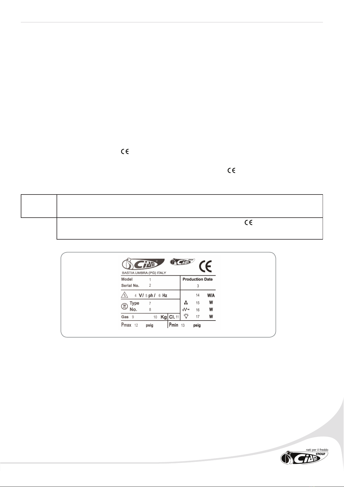
The facsimile of the identi cation plaque placed on the machine and of the Declaration of Conformity now
follow.
NOTE
ANY AMENDMENTS MADE TO THE MACHINE IMMEDIATELY VOIDS ALL CERTIFICATION.
IN THIS CIRCUMSTANCE THE MANUFACTURER DECLINES ALL RESPONSIBILITY.
1. Appliance business name
2. Appliance identi cation serial number
3. Appliance production date
4. Electric power supply voltage
5. Number of phases of electric power supply
6. Frequency of electric power supply
7. Refrigerating compressor model
8. Number of compressors used
9. Type of coolant used
10. Coolant weight
11. Reference climatic class for the appliance functioning (Cl.3 =
+25°C/60% U.R.; Cl.4 = +30°C/55% U.R.)
12. Plant high pressure side pressure test
13. Plant low pressure side pressure test
14. Nominal power/current absorbed during refrigeration
15. Maximum power absorbed during defrosting
16. Nominal power absorbed by the heating elements (only if higher
than 100W)
17. Lighting nominal power

14
4.1.4 Intended use and limits of usage
This refrigerating equipment is used exclusively for the display and sale of confectionary and delicatessen products.
It is also possible to display small sized packaged dairy products as well as sliced and packaged cold cuts, which need
to be positioned in a way that does not exceed the load limits indicated within this manual.
!ATTENTION
USING THE MACHINE FOR ANY USE OTHER THAN FOR PRESERVING AND DISPLAYING FOODSTUFFS IS
CONSIDERED AS IMPROPER USE. IN THIS CIRCUMSTANCE ALL RESPONSIBILITY IS DECLINED IN CASE OF
DAMAGE TO THINGS AND/OR PEOPLE, AND, FURTHERMORE, VOIDS ALL WARRANTY.
THE MANUFACTURER DECLINES ALL RESPONSIBILITY IN CASE OF TAMPERING WITH THE MACHINE FOR NON
AUTHORISED AMENDMENTS OR FOR MAINTENANCE OPERATIONS PERFORMED BY UNQUALIFIED STAFF.
DANGER
IN CASE OF ANOMALOUS MACHINE BEHAVIOUR, ANY TYPE OF INTERVENTION IS TO BE PERFORMED BY
MAINTENANCE OPERATORS.
4.2 Disposal of worn-out materials
Under normal functioning conditions the machine does not pollute the environment.
At the end of the display cabinet functioning life-span or whenever it is necessary to denitely place the equipment
out of service, it is recommended to:
• Make the display cabinet unusable by disconnecting the electric power supply.
• Remove any sliding closures, sides, or panelling that could constitute a source of danger.
• Remove all rubber parts (Seals, etc...)
IMPORTANT INFORMATION FOR THE USER ACCORDING TO DIRECTIVE “RAEE” 2002/96/EC AND
SUCCESSIVE MODIFICATION 2003/108/EC DEALING WITH ELECTRIC AND ELECTRONIC EQUIPMENT
WASTE.
According to Directive “RAEE” 2002/96/EC and successive modication 2003/108/EC, if the purchased
equipment is marked with the following symbol of a crossed out rubbish container with wheels, it means that
after the product life-span it needs to be collected separately from other waste.
Separate collection of this equipment for recycling, once its life-span has been exceeded, is organised and managed by the
manufacturer.
Therefore, the user who wishes to dispose of this equipment must contact the manufacturer and follow the method used to
allow separate collection for recycling of equipment that has reached the end of its life-span.
Suitable collection for successive start-up of the equipment for recycling, treatment and compatible environmental disposal
contributes in avoiding possible negative effects on the environment and on health, and favours the re-use and/or recycling
of the materials composing the equipment.
!ATTENTION
THE ILLEGAL DISPOSAL OF THE PRODUCT ON BEHALF OF THE HOLDER, IMPLIES THE APPLICATION OF
ADMINISTRATIVE SANCTIONS PROVIDED BY THE REGULATION IN FORCE.
IMPORTANT
IN CASE THE SYMBOL OF THE CROSSED OUT RUBBISH CONTAINER WAS NOT PRESENT ON THE EQUIPMENT, IT
MEANS THAT THE DISPOSAL OF THE SAME PRODUCT IS NOT THE MANUFACTURERS’ RESPONSIBILITY. IN SUCH
CASE, HOWEVER, THE REGULATION IN FORCE REGARDING THE WASTE DISPOSAL ARE VALID.
The refrigerating circuit components must not be cut and/or separated but must be taken to the specialised centres intact for
the recovery of the refrigerating gas.
Specic regulations exist in every nation regarding the disposal of these materials in order to safeguard the environment.
It is the Client or Maintenance operator obligation to be aware of the laws in force in this regard in his country
and to operate in order to comply with these legislations.
15
!ATTENTION
REMEMBER TO COMPLY WITH THE LAWS IN FORCE WITH REGARD TO THE DISPOSAL OF REFRIGERATING LIQUID
OR MINERAL OILS.
SUPPLEMENTARY INFORMATION
FURTHER INFORMATION ON THE DISPOSAL MODALITIES OF REFRIGERATING LIQUID AND OILS AND OTHER
SUBSTANCES CAN BE FOUND ON THE SAFETY CARD RELATING TO THE SAME SUBSTANCES.
4.3 Safety applied on the machine
The machines provided with the following safety devices
Safety present on the Machine
FIXED PROTECTIONS
SECTIONING THE ELECTRIC POWER SUPPLY
4.3.1 Fixed protections
The xed type protections are constituted by xed perimeter covers, which function is to prevent access to the
internal parts of the equipment.
DANGER
FOLLOWING MAINTENANCE , IT IS FORBIDDEN TO RE-START THE MACHINE, WITHOUT CORRECTLY RESTORING
THE PANELS.
ATTENTION
Periodically check that the xed covers and respective attachments to the structure are intact, with particular
attention to the protection panels.
4.3.2 Sectioning the electric energy
The appliance is not equipped with a sectioning device able to remove the electric power supply voltage to the two
poles (phase and neutral) at the same time. In fact, pressing the OFF key on the electronic control unit only stops the
display cabinet functioning, but does not remove the current from the electric components inside the display cabinet
(lights, fans and electric terminal board). The sectioning can happen through the plug socket, but it is recommended
that the installer positions, upstream of the appliance, a multiple pole switch which guarantees the complete
disconnection of the display cabinet from the mains.
DANGER
PRESSING THE OFF KEY ON THE ELECTRONIC CONTROL UNIT STOPS THE DISPLAY CABINET FUNCTIONING BUT DOES NOT
CAUSE THE SECTIONING OF THE ELECTRIC ENERGY. IT IS THEREFORE COMPULSORY, IN CASE OF MAINTENANCE INTERVENTION,
TO COMPLETELY DISCONNECT THE DISPLAY CABINET FROM THE MAINS BY REMOVING THE MAINS PLUG OR ACTING ON THE
MAIN SWITCH, INSTALLED UPSTREAM OF THE DISPLAY CABINET.

16
DANGER
THE SECTIONING SWITCH CANNOT BE PADLOCKED IN THE OPEN CIRCUIT POSITION. THEREFORE REMEMBER, IN CASE OF
MAINTENANCE INTERVENTION WHERE THE OPERATOR IS NOT ABLE TO PREVENT THE ACCIDENTAL CLOSURE OF THE CIRCUIT
ON BEHALF OF OTHERS, TO COMPLETELY DISCONNECT THE APPLIANCE FROM THE MAINS.
4.4 Residual risks
The areas or parts at risk have been evaluated during planning. All precautions have been taken to avoid risks to persons
and damages to the SERIES 750-900 Refrigerated Display Cabinets as indicated in the previous paragraphs.
Position 1 Position ON, circuit CLOSED, machine with voltage
Position 2 Position OFF, circuit OPEN, machine without voltage
!ATTENTION
PERIODICALLY CHECK THE FUNCTIONING OF ALL SAFETY DEVICES.
DO NOT DISMANTLE THE MACHINE FIXED TYPE PROTECTIONS.
DO NOT INTRODUCE OBJECTS OR FOREIGN TOOLS IN THE APPLIANCE OPERATION AND WORK
AREA.
Despite the machine being equipped with the above stated safety systems, certain risks still remain which cannot
be removed but reduced, through corrective actions on behalf of the nal integrator and correct operational
modalities.
Following is a summary of the risks which remain on the machine during:
• Normal functioning
• Regulation and adjustment
• Maintenance
• Cleaning.
4.4.1 Electrocution
• Risk of break or damage with possible lowering in the safety level of the electric appliance components following
a short circuit.
• Before inserting the electric power supply, ensure there are no maintenance interventions in process.
!ATTENTION
BEFORE CONNECTING, CHECK THAT THE D.C. CURRENT IN THE INSTALLATION POINT IS NOT
HIGHER TO THAT INDICATED ON THE PROTECTION SWITCHES PRESENT ON THE ELECTRIC CONTROL
BOARD. IF SO, THE USER MUST ARRANGE FOR THE APPROPRIATE LIMIT DEVICES.
!ATTENTION
IT IS FORBIDDEN TO CARRY OUT ANY TYPE OF ELECTRIC MODIFICATION IN ORDER NOT TO CREATE
ANY UNFORESEEN ADDITIONAL DANGERS AND RISKS.
17
4.4.2 Fire
DANGER
IN CASE OF FIRE IMMEDIATELY DISCONNECT THE MAIN SWITCH FROM THE MAINS.
4.4.3 Explosive atmosphere
The machine is not suitable to work in classied environments.
• It is forbidden to use the same in an atmosphere classied or partially classied.
4.4.4 Slipping
Any leaks of lubricants in the areas around the machine can cause personnel to slip.
• Check there are no leaks and always keep such areas clean.
4.4.5 Tripping
The untidy material deposit can generally constitute a danger of tripping and partially, or completely, limit the escape
ways in case of need.
Ensure operational, transit areas and escape ways are not obstructed and in compliance with the regulations in
force.
4.4.6 Circuit faults
Due to possible faults, the safety circuits may loose part of their efciency with relative lowering of safety level.
• Periodically check the functioning status of the safety devices present on the machine.
4.5 Monitory plaques
Due to the residual risks, of various nature, identied on the machine, CIAM Spa has equipped the SERIES 750-900
Refrigerating Display Cabinets with danger, warning and obligatory monitory plaques, dened in compliance with the
European regulation relating to the graphic symbols to be used on the plants (Directive 92/58/EEC).
The plaques in question are in a clearly marked position.
!ATTENTION
IT IS FORBIDDEN TO REMOVE THE MONITORY PLAQUES PRESENT ON THE MACHINE.
MABO SRL DECLINES EVERY RESPONSIBILITY ON THE SAFETY OF THE SERIES 750-900 REFRIGERATED DIS-
PLAY CABINETS IN CASE OF NON COMPLIANCE WITH SUCH PROHIBITION.
!ATTENTION
THE USER MUST REPLACE THE MONITORY PLAQUES WHICH, FOLLOWING WEAR, ARE ILLEGIBLE.
18
5.1 General information
!ATTENTION
CAREFULLY READ THE FOLLOWING AS THE INSTALLATION OPERATIONS (INCLUDING MOUNTING
AND START-UP) CAN CAUSE RISKS FOR THE UNSKILLED PERSONNEL, AS THEY REQUIRE KNOWL-
EDGE OF THE MACHINE.
5.2 Choosing a room and veri cation of the requisites for the
installation
The machine installation area must be suf ciently wide to respect the:
• operational spaces
• passage ways
• escape ways
The oor of the room chosen for the installation must be regular, levelled and in compliance with the application
speci cations and able to support the machine weight speci cations.
The room must also be equipped with attachments for electric and uidics energy necessary for the functioning of
the machine.
The room must be equipped according to the safety regulations in force in the using country and guarantee airing
and earthing of the appliances.
!ATTENTION
TO HOIST THE PACKAGES, AN ADEQUATE HOISTING MEAN IS NECESSARY, BEARING IN MIND THE
SAFETY MARGINS PROVIDED BY LAW AND SAFETY REGULATIONS IN FORCE.
5.3 Moving the appliance
• As far as possible, the operational area must be free from materials which can prevent or limit the view, create
obstruction or tripping.
• The packages composing the machine must only be moved using a hoisting trolley with adequate power
and capacity for the weight of the appliance to be moved, as per the technical table of the speci c appliance
purchased. If necessary, hoisting accessories of approved type and adequate capacity, higher than the weight
to be hoisted, can be used. The machines’ weight is reported in the technical data table of the same.
• It is therefore the responsibility of the installer to use hoisting means of adequate capacity.
• Before hoisting the appliance, check there are no mobile parts or tools on the same.
• Check that the load is correctly balanced: slightly lift the load from the ground and check, before proceeding
further, that it is horizontal. If not, lay down the load, reallocate the slings and repeat the operation until
correctly balanced.
• In case of hoisting with forks, check that they are only in contact with the lower part of the appliance frame
and not with other perishable parts (carter, power supply cord etc.), which might compromise the safety of the
product during start-up.
5. INSTALLATION
19
!ATTENTION
TO HOIST THE PACKAGES AN ADEQUATE MEAN IS NECESSARY, BEARING IN MIND THE SAFETY
MARGINS PROVIDED BY LAW AND SAFETY REGULATIONS IN FORCE.
!ATTENTION
IN CASE OBSTRUCTIONS, AND/OR OPERATIVE SITUATION, DO NOT ALLOW THE OPERATOR TO
HAVE A PERFECT VIEW, PERSONNEL WITH THE TASK OF SIGNALLING SHOULD BE PLACED OUTSIDE
THE ACTION RANGE OF THE HOISTING MEAN.
Once the perfect balance has been obtained, proceed to hoisting and moving the load.
ATTENTION
NEVER TRANSIT UNDERNEATH SUSPENDED LOADS.
NEVER MOVE THE LOAD OVER PERSONNEL OPERATING IN THE INSTALLATION AREA.
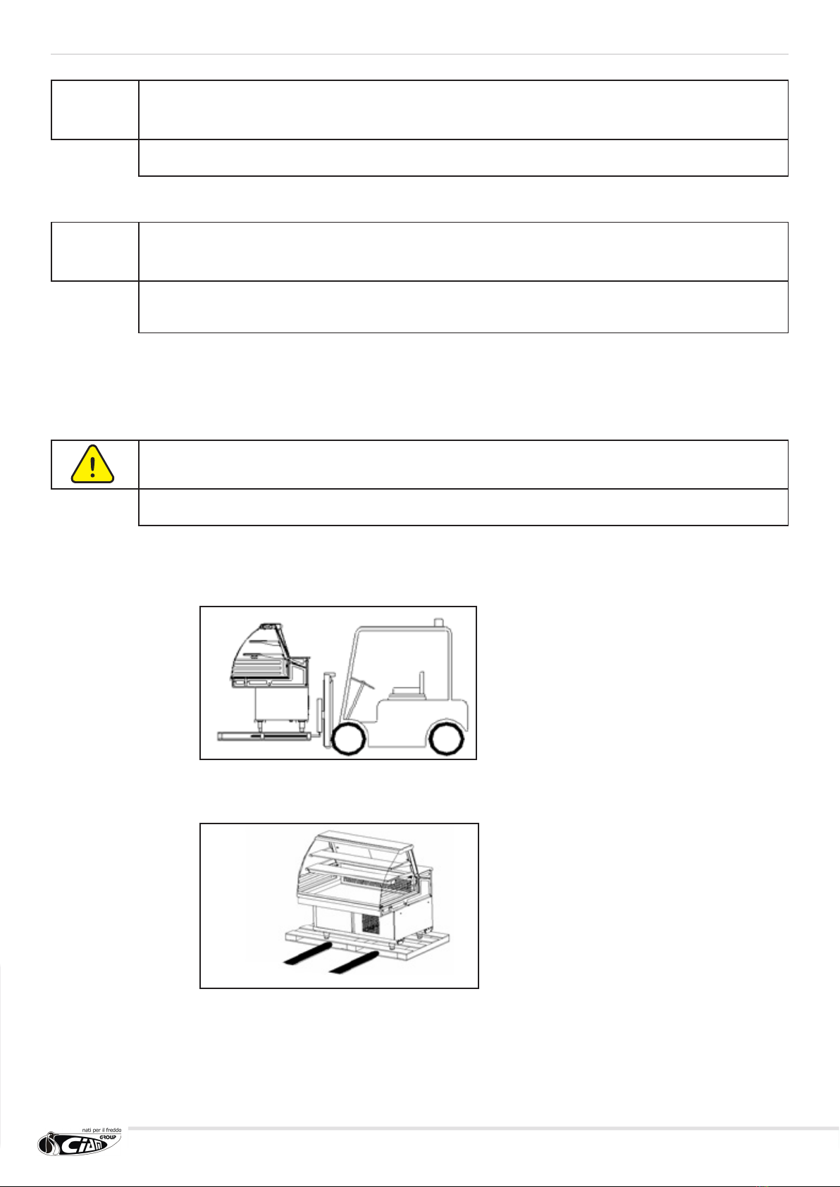
• The moving, from the transport mean to the nal site, must be carried out with adequate hoisting and moving
mean for the weight of the appliance, which should always be in a stable equilibrium for the integrity of personnel
and of the same appliance (g.5.1.1).
• The appliance can be transported with or without packaging: if present, it is provided with a step-board for
moving with fork lift. In any case, the application point of the hoisting means or the blades of the elevator mean,
must be respectively centred on the centre line of the appliance (g.5.1.2).
• During transport, do not let the appliance undergo crashes or jolts in order not to damage the structure,
especially the glass one.
• Do not drag the appliance on the oor and do not push it forcing the glass mount.
(g.5.1.1).
(g.5.1.2).
lift here
20
5.4 Storing the appliance
• For storing with packaging, pay attention to that reported with regard to the same packaging.
• The storing temperature can be between -15°C and +55°C and humidity between 30% and 90%.
• The appliance must always be protected from sun and bad weather.
• Should the appliance stay in a warehouse for a long time before being used, leave it inside its original packaging,
which guarantees the most adequate protection.
5.5 Unpacking the appliance
Before accepting the appliance from the carrier, check its condition.
Should there be evident damages, show them to the carrier and sign, with reserve, the packing list.
Any damages caused by transport or incorrect storage, cannot be attributed to the manufacturer.
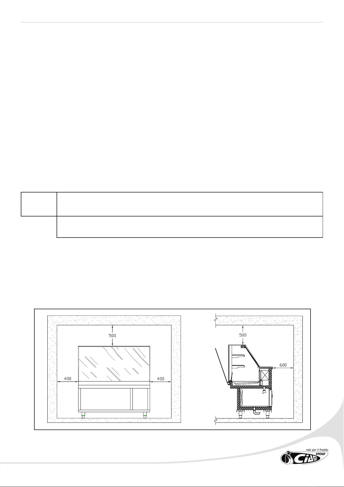
5.6 Installation, positioning and environmental conditions:
For the correct positioning, carry out the following operations:
Position the display cabinet leaving a space sufcient for the safe use and maintenance, as provided by the normative
UNIEN 292/2.
!ATTENTION
THE NON COMPLIANCE WITH THE DISTANCES INDICATED, AS WELL AS NOT GUARANTEEING
A CORRECT FUNCTIONING OF THE APPLIANCE, CAN ALSO PREVENT ANY MAINTENANCE
INTERVENTION.
In case a step-board for the operator is present, it must have an easily removable part in correspondence with the
condensing unit so that it can be removed for maintenance operations.
21
Check that there is a suitable earthing plant as provided by the respective EN.
Ensure that the condensing compressor group is in a free air change condition.
The appliance must be positioned at (check with spirit level) in order to guarantee better
functioning.
Ensure that the appliance is installed away from sources of heat (radiators, stoves etc.) and away
from continuous air movements (for example, caused by fans, air conditioning inlets etc.).
Do not position the appliance near currents of air (near doors, windows, air conditioning plants
etc.) which exceed the speed of 0.2m/sec.
Ensure that the inuence or direct exposure to sunlight and anything which might cause the
temperature inside the refrigerating room to rise is not possible.
Therefore do not position the appliance near sources of heat (direct sunlight, heating plants,
incandescent lamps etc.).
Do not position the appliance in rooms in the presence of explosive gasses, open air and therefore,
atmospheric agents.
Once positioned in the desired area, lay it at using the adjustable feet
• If the cabinet is moved, repeat the levelling control.
• Before connecting the cabinet to the mains, ensure that the plaque data correspond to the
electric plant features to which it will be connected.
• For the correct functioning of the cabinet, the room temperature and humidity must respect
the parameters provided in normative EN-ISO 23953 - 1/2, which provides Climatic Class 3
(+25°C; U.R. 60%). (Our products satisfy the 4 +30°C; U.R. 55%)
N.B. All these operations must only be carried out by qualied personnel.
The refrigerating appliance requires precise environmental conditions in order to offer the performances for which it
was designed; therefore, the housing environment, will have to respect the following indications:
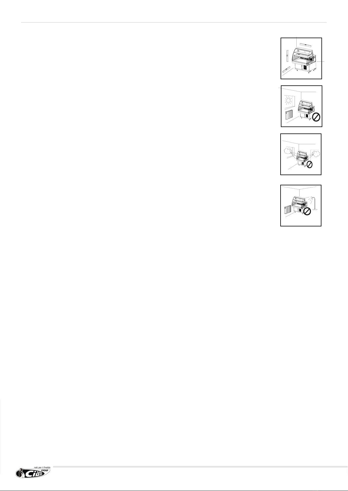
• The support surface must be perfectly levelled; if not, bring the appliance into horizontal position (check with
spirit level) to guarantee the perfect evacuation of the defrosting water, to avoid annoying noises caused by the
vibrations and to assume a better appearance (g.5.4.1).
• The appliance, and its displaying compartment, must not be hit by sun rays or reections; the appliance must
always be under cover, inside the premises or covered by a curtain. The non compliance with the above, causes
an anomalous increase of the exposed product temperature, which cannot be remedied in any way, and an
increase in energy consumption (g.5.4.2).
• The appliance must not incur permanent air currents caused by open premises doors or windows, ceiling fans, air
and air conditioning inlets facing the appliance area. The non compliance with the above, causes an anomalous
increase in the exposed product temperature and an excessive build up of brine on the evaporator and fans,
compromising the correct air circulation (the immediately detectable effect is the alteration in the product
consistency g.5.4.3).
• The appliance must not be placed near radiating sources of heat, such as radiators, stoves, ovens, intense
sources of articial light, etc. (g.5.4.4).
• The appliance must have sufcient space in order to allow a correct service to customers, make the maintenance
interventions easy, guarantee the necessary air inlet to the condensing cooler; the outgoing hot air from the
latter must not be obstructed and must not cover other appliance, in order not to compromise the correct
functioning.
This manual suits for next models
1
Table of contents
Popular Refrigerator manuals by other brands

Viking
Viking Quiet Cool FDBB5361R Planning and design guide

Svan
Svan SVCR187NFX instruction manual

Atlantic
Atlantic ATLKS84W10A+ 1 Series user manual

Vestfrost
Vestfrost FZ 316 Instructions for use

Bosch
Bosch KDL Series operating instructions

Kelvinator
Kelvinator COMMERCIAL FREEZER/REFRIGERATOR GLASS DOOR... Use & care guide


DF user manual")


