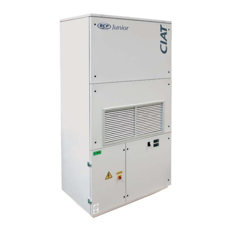
CIAT COMFORT LINE User manual

COMFORT LINETM
06 - 2022
EN7533229-03
Instruction manual

COLIS / PACKAGE
35 kg
Haut / To p
Bas / Bottom
COLIS
PACKAGE
COLIS
PACKAGE
+50°C
-10°C
COLIS
PACKAGE
COMFORT LINETM II

Fig. 1
baej
i
p
f
o
h n
m
c
g
idk
n
q
III COMFORT LINETM

Fig. 2
Designation/Description
Ref. produit/Item Ref.
An/Year
N° série/Serial Nbr
Repère/PartComposants/Components
Moteur/Motor (Ph/Hz/V) Batterie/Hydro. coil Fluide/Fluid
Maxi pressureElec Element (Ph/Hz/V)P. moteur/Motor P. (W)
I. moteur/Motor I. (A) Elec Element P. (W)/I.(A) Cablage/Wiring
N° Declaration CEElec Diagramtr. mn - 1/r.p.m.
2016 02461545/0001 E39H TH8 230TH14 ~
7412910.430615 CFL12B 2TG500 LY . .
1+N 50/60HZ 230V/220V+T 2T2N EAU
1600000 PA (16BAR)
7341384.007349014
1+N 50/60HZ230/220V
531
74/89
0.32/0.38 500
BCD
F
EJ
KHG
L
I
-a-
-b-
Fig. 3
COMFORT LINETM IV

Fig. 4
Fig. 5
a
b
a
c
VCOMFORT LINETM

Fig. 6
148
50
40 120
T1 = 128
T2,T3 = 160
T4,T5 = 193
T6 = 40
32
20
55
200
a b
Fig. 8
a
b
Fig. 7
COMFORT LINETM VI

Fig. 10
Fig. 9
a
b
VII COMFORT LINETM

Fig. 12
Fig. 11
a
d
e
bc
COMFORT LINETM VIII

i
k
b
a
a
d
d
fg
j
i
Fig. 13
c
e
h
h
IX COMFORT LINETM

Fig. 14
b
a
c
cdd
ef
COMFORT LINETM X

Fig. 15
a
b
b
c
dd e
XI COMFORT LINETM

Fig. 16
Fig. 17
e
f
b
e
h
g
COMFORT LINETM XII

Fig. 18
aab
XIII COMFORT LINETM

Fig. 19
T0 T6 : 590 1313
T0 : 538, T1 T5 : 649
T6 : 368
T0 : 131
T1 <-> T6 : 192
T6 : 420
I . Y . H .U
T0 : 240
T1 : 215
T2 . T3 : 245
T4 . T5 : 280
T6 : 375
LI . LY
T1 : 290
T2 . T3 : 320
T4 : 355
T0 : 485
T1.T2 : 692
T3.T4 : 992
T5.T6 : 1292
T0 : 780
T1 . T2 : 898
T3 . T4 : 1198
T5 . T6 : 1498
T0 : 225
T1 <-> T6 : 209
134
75
COMFORT LINETM
Poids/Weight/Gewicht/Peso/Peso/Gewicht/Вес/ağırlık
T0 T1 T2 T3 T4 T5 T6
I15 25 27 36 39 47 60
Y15,5 27 29 39 42 51 66
H16 34 34 46 49 60 77
U21 35 38 51 57 - -
COMFORT LINETM XIV

CONTENTS
1 - UNPACKING, CHECKING AND STORING THE UNIT ...................................................................................16
2 - HANDLING ......................................................................................................................................................17
3 - DESCRIPTION OF THE UNIT (FIG. 1)............................................................................................................18
3.1 - Name plate (Fig.2).......................................................................................................................................18
3.2 - Models.........................................................................................................................................................19
3.3 - Dimensions and weight ...............................................................................................................................19
4 - NSTALLATION AND CONNECTIONS ............................................................................................................20
4.1 - Mechanical connections..............................................................................................................................20
4.2 - Air connections............................................................................................................................................20
4.3 - Hydraulic connections .................................................................................................................................20
4.4 - Condensate pump draining connection.......................................................................................................22
4.5 - Connecting the condensate drain pump (option) ........................................................................................22
4.6 - Electrical connections..................................................................................................................................24
5 - SERVICING AND MAINTENANCE .................................................................................................................27
5.1 - Air lter ........................................................................................................................................................27
5.2 - Condensate drain pan.................................................................................................................................27
5.3 - Fan motor assembly....................................................................................................................................28
5.4 - Heat exchange coil......................................................................................................................................29
6 - CERTIFICATE OF CONFORMITY...................................................................................................................30
7 - TESTING & WARRANTY ................................................................................................................................30
8 - SAFETY CONSIDERATIONS RELATING TO FINAL SHUT-DOWN ..............................................................31
EN-15 COMFORT LINETM

1 - UNPACKING, CHECKING AND STORING THE UNIT
Thank you for purchasing a CIAT unit. We trust that this unit will give you complete satisfaction.
To ensure correct operation, all connections (electrical, hydraulic, etc.) must be made in accordance with best
industry practice and the regulations in force in the country of installation.
Your unit must be maintained and installed as recommended in this manual.
Each device bears a name plate. The reference number shown on the name plate must be quoted in all
correspondence.
It is the recipient's duty to inspect the contents of the packages upon receipt:
■In the event of missing items, the customer must provide the exact number of parcels delivered.
■If any damage is found on delivery, report it on the delivery receipt in the presence of the delivery driver before
the delivery note is signed.
In accordance with Article 133 of the French Code of Commerce, these claims must be reported
to the carrier by registered letter within three business days of receipt. The terms "conditional"
and "pending unwrapping" shall have no value. The client must unwrap the goods in the presence
of the driver. Claims must be made at the time of delivery and be described in detail.
COMFORT LINETM EN-16

2 - HANDLING
For your safety, wear protective gloves
The unit must be handled with care and kept at. Impacts may cause damage to the frame or the
body of the unit and adversely aect its main functions and its appearance.
The unit should preferably be lifted by its mounting holes (Fig.1, m) and never by the condensate pan or the collars.
It is possible to carry out the installation using a fork-lift truck, as long as care is taken not to damage the unit.
The unit is placed inside the suspended ceiling. If the return has no duct, ensure that the rear of the unit is at a
sucient distance from the wall (X = min. 250 mm).
EN-17 COMFORT LINETM

3 - DESCRIPTION OF THE UNIT (FIG. 1)
The COMFORT LINE™ (CFL) unit that you have just purchased is part of a range of comfort units with high available
static pressure. It is used for heating, cooling, dehumidication and air ltration. It includes a coil with one or two
hot water or cold water supply circuits and may include an electrical heater for heating.
a - Fan motor assembly access panel and lter
b - Filter runner except for size 0
c - Supply air collars
d - Header couplings
e - Coil lower access panel
f - Exchanger coil
g - Air bleed and drain valves
h - Fan motor assembly
i - Electrics box
j - Condensate drain pan
k - Condensate drain pump
l - Condensate drainage
m - Oblong mounting hole Ø12 x 30 mm
n - Air lter
o - Fresh air inlet knockout (opposite side to electrics
box)
p - Resilient mount
q - Return air grille
3.1 - Name plate (Fig.2)
The name plate contains all the information required to identify the unit and its conguration. This plate is placed
on the technical side that has all the connections, above the fresh air inlet.
Before contacting us, please note the serial no. and the designation.
BCode
CSerial number
DUnit designation
ERated motor power
FMotor rotation speed
GCoil type
HWiring diagram reference
IMotor speed wiring
JMaximum operating pressure
K Electric heater specications (if tted)
LEC declaration number
This device may be used by children aged eight and over, and by persons with limited physical,
sensory or mental capabilities, or by persons with insucient experience or knowledge, provided
that they are being correctly supervised or provided they have received instructions on how to
use the device in complete safety, ensuring that they have a full understanding of any risks
involved. Children must not play with the unit. User cleaning and maintenance must not be
performed by children.
During normal use, this unit is intended to operate under the following conditions:
■Maximum altitude: 2000 m,
■Minimum and maximum storage temperatures: -20 °C/+65 °C,
■Minimum and maximum operating temperatures: 0 °C/+ 40 °C,
■Indoor return air maximum humidity level: 27°C DB (dry bulb) at 65% RH (Relative Humidity),
■Clean interior environment (no corrosive substances present).
The device is designed for indoor use, and requires protection from any form of impact. Protection
rating IP 20 IK02.
This device is designed to operate in an over-voltage category II and pollution degree 2 environment,
in accordance with IEC standard 664-1.
To ensure a pollution degree 2 environment, the device must be protected from water and oil
splashes, and the dust allowed to settle on it must be limited.
COMFORT LINETM EN-18

3.2 - Models
The COMFORT LINETM is available in 8 standard models:
I : Metal sleeve on the discharge (optional on size 0)
and optional metal sleeve on the intake
Y : Supply plenum with collars for round ducts + metal
sleeve optional on intake
H : Return and supply plenum with collars for round ducts
U : Return and supply plenum with lateral collar for round
ducts.
LI : Air recovery grille integrated into the device, with air
supply via rectangular sleeve
LIk : LI model + air distribution kit
LY : Air recovery grille integrated into the device, with
air supply via collars
LYk : LY model + air distribution kit
3.3 - Dimensions and weight
■Dimensions and weight, see Fig. 19.
3 - DESCRIPTION OF THE UNIT (FIG. 1)
EN-19 COMFORT LINETM

4 - NSTALLATION AND CONNECTIONS
To prevent injury or damage to the unit or room, work must only be carried out by qualied
personnel.
4.1 - Mechanical connections
Ensure that the suspended ceiling panels can be
easily removed and that there is enough space to
carry out maintenance and servicing operations.
The COMFORT LINETM must be suspended from the
ceiling using 4 or 6 threaded rods either 6 mm or 8 mm
in diameter (not supplied), which are xed to the unit's
4 or 6 oblong holes using anti-vibration resilient mounts
(optional, g.3, a) or a nut/washer assembly positioned
on either side of the mounting bracket (g.3, b).
Note: CIAT strongly recommends the use of anti-
vibration resilient mounts when securing the unit,
in order to reduce the transmission of vibrations
through the building structure during operation.
For LI, LIk, LY and LYk models, the unit should ideally
be positioned inside the suspended ceiling in the
entrance corridor of rooms, with the supply air opposite
the window. The unit must never be placed in the centre
of the room.
■The unit must be perfectly level in
relation to the suspended ceiling to
prevent condensate draining problems
(see procedure for removing the
condensate pan on page 10.)
■If a room thermostat is tted, place it on
an inside wall (not behind a door) and at
a height of 1,50 m from the oor. Keep it
away from sunlight and all sources of
heat.
4.2 - Air connections
4.2.1 - Air quality
Comfort units are not designed to control the humidity
of outside air. Fresh air handling must be provided by
an independent system in accordance with accepted
engineering practice (see CIAT air handling unit ranges).
All collars must be connected, whatever
the model. None must be capped, either for
the supply or return air.
4.2.2 - Fresh air knockout
If the fresh air return leads directly outside, the duct must
not exceed 5 metres in length. The fresh air temperature
must not be below -10 °C. A rain guard grille and a lter
must be tted (at the installer's expense) to prevent water
or other material entering the duct from outside. If an
auxiliary fan is being used (supplied by the installer), the
ow of fresh air must be limited to 10% of the unit's
nominal ow rate to prevent noise, coil frosting or air
lter bypass problems.
4.2.3 - Adjusting the fresh air collars
(Fig.4):
Either remove or leave on the shims needed to obtain
the desired ow rate. The ow rate ranges are given on
the label on the casing. 2 shims for minimum ow, 1 shim
for medium ow, no shims for maximum ow.
The pressure dierence must be between 50 and 100
Pa in order to obtain the desired ow rate.
Maintain the controller in the "BAS" (down) position.
4.2.4 - Fitting and adjusting the return air
grille for assembly versions LI/LY (Fig.5).
The return air grille is tted using 11 screws (a).
To adjust the height of the grille, remove the 4 panel
screws (b) and adjust to the required height (max.
clearance 40 mm). Secure the 4 screws once more (c).
4.3 - Hydraulic connections
Water always ows into the bottom of the coil and exits
at the top.
For size 0, the pipes are positioned in the suspended
ceiling as shown in Fig. 6, a. For sizes 1 to 6, the pipes
are positioned in the suspended ceiling or raised oor
as shown in Fig. 6, b.
The coils are equipped (g.7) with a header coupling
with at face swivel nuts with a female thread, diameter
G ½˝ or G ¾˝ depending on the size of the unit, and an
O-ring (supplied by CIAT).
The header coupling is equipped with an air bleed valve
(g. 8, a) at the high point with partial draining at the low
points (g. 8, b) that can be manoeuvred using a 7 mm
Allen key or a at-blade screwdriver.
COMFORT LINETM EN-20
Other manuals for COMFORT LINE
2
Table of contents
Other CIAT Air Handler manuals

CIAT
CIAT COMFORT LINE User manual

CIAT
CIAT Floway Access 1000 User manual

CIAT
CIAT FLOWAY Use and maintenance manual

CIAT
CIAT ciatronic micro 2000 Guide

CIAT
CIAT FLOWAY CLASSIC RHE User manual

CIAT
CIAT Junior BCP Series Guide

CIAT
CIAT AirCompact Control Use and maintenance manual

CIAT
CIAT CLIMACIAT airtop Series User manual
Popular Air Handler manuals by other brands

Trane
Trane CeilAir CW Installation, operation and maintenance

emmeti
emmeti UTO-EC-AP Installation and use manual

Trox Technik
Trox Technik X-CUBE X2 Transport and installation manual

BLAUBERG Ventilatoren
BLAUBERG Ventilatoren KOMFORT EC U330 Operation manual

Bryant
Bryant 479 installation instructions

Salda
Salda Smarty 2R VE User and Service Technical Manual