Page 6
I-UNIT COMPONENTS
The gas valve, combustion air inducer and burners can be
-
blower section.
SL280DFNV units are factory equipped with a bottom re-
removed as required for bottom air return. Markings are
.
ELECTROSTATIC DISCHARGE (ESD)
Precautions and Procedures
CAUTION
Electrostatic discharge can aect
electronic components. Take precautions
to neutralize electrostatic charge by
touching your hand and tools to metal
prior to handling the control.
A- Control Box
1. Control Transformer (T1)
A transformer located in the control box provides pow-
er tothe low voltage section of the unit. Transformers on
secondary.
2. Door Interlock Switch (S51)
-
ries with line voltage. When the inner blower access panel
is removed the unit will shut down.
SureLight®Integrated Control
Interlock Switch
Transformer
Circuit Breaker
FIGURE 2
3. Circuit Breaker (CB8)
The switch provides overcurrent protection to the trans-
exceeds this limit the breaker will trip and all unit opera-
tion will shutdown. The breaker can be manually reset by
.
PRESS TO RESET
FIGURE 3
WARNING
Shock hazard.
Disconnect power before servicing. Integrated
control is not eld repairable. If control is
inoperable, simply replace entire control.
Can cause injury or death. Unsafe operation will
result if repair is attempted.
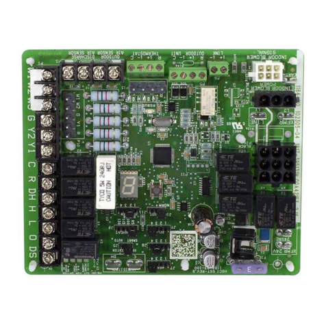
4. Integrated Control (A92)
Units are equipped with the communicating enabled Sure-
Light®two-stage, variable speed integrated control. This
control is used with any communicating enabled thermo-
stat as part of a communicating comfort system. The con-
trol can also operate with a non-communicating conven-
tional single or two-stage thermostat. The system consists
The control and ignitor work in combination to ensure fur-
nace ignition and ignitor durability. The control provides
gas ignition, safety checks and indoor blower control with
two-stage gas heating.
The furnace combustion air inducer, gas valve and indoor
blower are controlled in response to various system inputs
such as thermostat signal, pressure and limit switch signal
-
switch circuit is open. The control also has two unpowered
-
At the beginning of the heat cycle the integrated control
inducer prove switch. The control will not begin the heating
Likewise the integrated control will not begin the second
stage heating cycle if the second stage prove switch is
heat pre-purge, the control will allow second stage heat.
