CIAT AirCompact Control Use and maintenance manual

NA 13.12 B
03 – 2015
AirCompact Control
AirCompact
Control manual

2
CONTENTS
1
Supervision and control ......................................................................................................................4
1.1 The program................................................................................................................................................... 4
1.2 The HMI terminal........................................................................................................................................... 4
1.2.1 Using the HMI terminal keys ..................................................................................................................................5
1.3 The room terminal (Option) ....................................................................................................................... 6
1.3.1 Controls.....................................................................................................................................................................6
1.3.2 Displays.....................................................................................................................................................................7
1.3.3 Room terminal information, settings and browsing.............................................................................................8
1.3.4 Managing alarms......................................................................................................................................................8
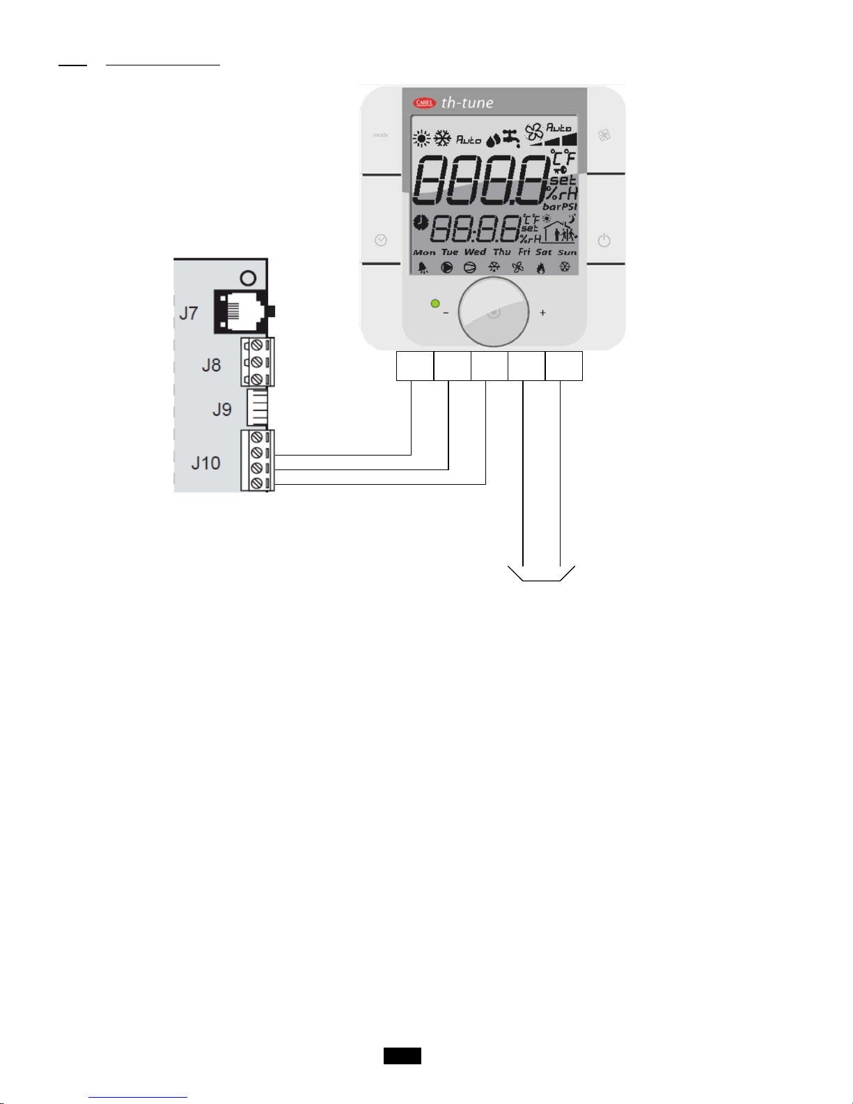
1.3.5 Electrical connections............................................................................................................................................10
1.4 The controller.............................................................................................................................................. 11
1.5 Description of the air handling units..................................................................................................... 11
1.6 Functional analysis of the control......................................................................................................... 12
1.6.1 Management of on and off modes.......................................................................................................................12
1.6.2 Safety and insulating damper...............................................................................................................................12
1.6.3 Antifreeze thermostat............................................................................................................................................12
1.6.4 Fire fault...................................................................................................................................................................12
1.6.5 Fan motors..............................................................................................................................................................13
1.6.6 Filtration...................................................................................................................................................................13
1.6.7 Temperature control..............................................................................................................................................14
1.6.8 Plate recovery.........................................................................................................................................................17
1.6.9 Electric heater.........................................................................................................................................................17
1.6.10 Free cooling........................................................................................................................................................18
1.6.11 Humidifier............................................................................................................................................................18
1.6.12 CO2air quality.....................................................................................................................................................18
1.6.13 Night cooling.......................................................................................................................................................19
1.6.14 The fault relays...................................................................................................................................................19
1.7 Controller inputs and outputs................................................................................................................. 20
1.7.1 Analogue inputs .....................................................................................................................................................20
1.7.2 Digital inputs ...........................................................................................................................................................20
1.7.3 Analogue outputs...................................................................................................................................................20
1.7.4 Digital outputs.........................................................................................................................................................20
2
Overview of the HMI module screens ............................................................................................22
2.1 Esc button.................................................................................................................................................... 22
2.1.1 Access level selection menu................................................................................................................................23
2.2 Setpoint menu............................................................................................................................................. 23
2.3 Machine parameters menu....................................................................................................................... 25
2.4 Adjustment parameters menu................................................................................................................. 28
2.5 Read-only parameters menu................................................................................................................... 31
2.5.1 Inputs.......................................................................................................................................................................31
2.5.2 Outputs....................................................................................................................................................................32
2.5.3 Calculated setpoints..............................................................................................................................................33
2.5.4 Counters..................................................................................................................................................................33
2.6 Fault memory menu................................................................................................................................... 34

3
2.7 Versions menu.............................................................................................................................................35
2.8 Time schedule menu..................................................................................................................................35
2.9 Communication menu................................................................................................................................37
2.10 Alarms menu.............................................................................................................................................37
2.11 Test mode menu......................................................................................................................................37
2.12 Access level menu..................................................................................................................................39
2.13 Master/Slave menu..................................................................................................................................40
3
Managing a network of controllers.................................................................................................40
3.1 pLAN electrical connections....................................................................................................................40
3.1.1 Connecting controllers to the pLAN.....................................................................................................................40
3.1.2 Connecting a remote screen to the pLAN ..........................................................................................................41
3.2 Addressing the pLAN.................................................................................................................................42
3.3 Changing the controller address............................................................................................................42
3.3.1 Addressing the HMI terminals..............................................................................................................................42
3.3.2 Assigning private and shared terminals..............................................................................................................43
3.3.3 Checking the pLAN address.................................................................................................................................44
3.4 State of the pLAN........................................................................................................................................44
4
Replacing the lithium battery...........................................................................................................44
5
Supervision...........................................................................................................................................44
5.1 CMS.................................................................................................................................................................44
5.2 The datapoint database.............................................................................................................................45
5.3 Modbus..........................................................................................................................................................45
5.3.1 Modbus RTU connection diagram.......................................................................................................................45
5.3.2 RS485 connection close-up..................................................................................................................................45
5.3.3 Modbus TCP connection.......................................................................................................................................46
5.3.4 Variables..................................................................................................................................................................47
5.3.4.1 Commands.....................................................................................................................................................47
5.3.4.2 Setpoints........................................................................................................................................................47
5.3.4.3 Reading parameters....................................................................................................................................49
5.3.4.4 Alarms.............................................................................................................................................................51
5.4 LON.................................................................................................................................................................52
5.4.1 LON scope of supply .............................................................................................................................................52
5.4.2 The digital datapoints.............................................................................................................................................52
5.4.3 The analogue datapoints.......................................................................................................................................54
5.5 KNX.................................................................................................................................................................55
5.5.1 Description of KNX communication card............................................................................................................55
5.5.2 Variables..................................................................................................................................................................56
5.5.3 Configuration process............................................................................................................................................62
5.5.4 CAREL plugin .........................................................................................................................................................62
5.5.5 Installing the plugin................................................................................................................................................62
5.5.6 Assigning the physical address............................................................................................................................64
5.5.7 Downloading the XML file.....................................................................................................................................65
6
Table of alarms.....................................................................................................................................66

4
1Supervision and control
1.1 The program
This air handling unit is managed by its controller. In addition to its control functions, it also monitors and detects any faults with the
air handling unit.
The HMI terminal displays the following data which can be edited at any time:
. values of connected sensors
. unit on/off cycles
. calibration of the sensors
. detection of alarms and log of the last 100
. the password-protected configuration and operating parameters
. device running times and time delays
. management of time programs (4 daily, 4 weekly and 4 yearly programs)
. language selection (French)
The connection with the pLAN network allows the program to use a terminal mounted on the front of the AHU and/or a wall-
mounted terminal installed in the room to be air conditioned.
IMPORTANT: To avoid any problems, the password must be known only by qualified personnel.
1.2 The HMI terminal
The terminal provided is equipped with a remote LCD display (8 lines x 22 columns) on the outside of the unit, which has 6 keys
(connected with a phone cable, max length 50m). It allows all of the program operations to be carried out. The terminal displays the
unit's operating conditions at any point in time and allows the parameters to be modified; in addition, it can be disconnected from
the main board as its presence is not strictly required.

5
1.2.1 Using the HMI terminal keys
Key
Description
Returns to the main Menu mask when pressed in any loop.
The Menu loop displays the state of the unit.
Provides access to the "Menu"
Resets all setpoints, parameters and time delay values to their factory settings.
The red button is used to display alarms and confirm acknowledgeable faults. It lights up
when an alarm is triggered.
The button has two functions:
1. used to manage the masks on the display (next mask)
2. used to adjust the values of the monitoring parameters (decrease)
The button has two functions:
1. used to manage the masks on the display (previous mask)
2. used to adjust the values of the monitoring parameters (increase)
Turns the unit on and off.
The
button is used to confirm changes. It is continuously backlit to indicate when the power is
on.

6
1.3 The room terminal (Option)
The terminal supplied is equipped with a digital display, 4 buttons and a rotary encoder.
Once installed in the premises, the device can measure the room temperature and enables remote control of the air handling unit.
1.3.1 Controls
1. Button not used
2. A short press will activate or deactivate operation in timed
zones if the time slot option has been authorised.
Press and hold (2 s) to access the timer and timed zones
setting menu.
3. Button for changing the ventilation speed
4. Button for switching the unit on or off (press and hold for 2s)
5. Encoder:
- Press to access the setpoints and confirm
- Turn to browse between menus and modify the parameters
1
2
3
4
5

7
1.3.2 Displays
1. Unit operating mode
2. Main display area (Big area)
3. Ventilation operating mode
4. Ventilation operating speed
5. Temperature unit
6. Indicates whether the value displayed in the main area is a setpoint
7. Indicates whether the value displayed in the main area is a humidity
8. Indicates the active time slot zone
9. Day of the week
10. Operating icons
11. Secondary display area (Small area)
12. Run time range mode
Details:
1. Unit operating mode
- : Unit in heating mode
- : Unit in cooling mode
2. Main display area
- Displays "OFF" when the unit is switched off manually via the room terminal
- Displays the ambient temperature
- Displays the temperature setpoint when the encoder is turned
- Displays the various menus during browsing
- Displays the various setting parameters
3. Ventilation operating mode
- : Indicates that the ventilation is active and in setpoint-based flow or Supply air duct pressure mode.
- : Indicates that the ventilation is in automatic mode based on the regulated temperature.
- No display: the unit has been switched off by the HMI terminal, by a major fault or to Standby by a time program.
4. Ventilation operating speed
- : The ventilation is operating at reduced flow or Eco Supply air duct pressure
- : The ventilation is operating at a nominal flow rate or Comfort Supply air duct pressure
5. Temperature unit
- °C: temperature expressed in degrees Celsius
- °F: temperature expressed in degrees Fahrenheit (not used)
6. Indicates whether the value displayed in the main area is a setpoint
After the encoder has been turned and then pressed, it is possible to modify the temperature setpoint characterised by the
indicator .
7. Area not used
8. Area not used
9. Area not used
10. Operating icons
Only the bell is used. It indicates the presence of a fault. This icon is inhibited when the faults are cleared via the HMI
terminal.
11. Secondary display area
Displays the time on the controller. This area can also be used for modifying the controller time.
12. Run time range mode

8
1.3.3 Room terminal information, settings and browsing
The diagram below shows the various browsing, information and setting options on the room terminal:
Terminal energising
A few seconds (2-3s)
Terminal initialising
A few seconds (2-3s)
Unit off
pressed
pressed
Unit on
(default
screen)
Communication fault
with the controller or
terminal presence not
validated in the controller
pressed and held
Encoder turned and pressed
Clock
modification
To modify and validate
the temperature setpoint.
Returns to the default
screen after a few
seconds.
Encoder turned
Not used
Encoder turned
Exits the alarm menu when
the encoder is pressed.
1.3.4 Managing alarms
When an alarm appears, it is accompanied by an acronym on the screen:
u1.3
Cn

9
To find out the reference for the alarm, simply press the and "mode" buttons for 3s:
To find out whether there is more than one active alarm, turn the encoder to access the full list.
List of alarms:
Messages
Room terminal
Messages
HMI terminal
AL01
Supply air motor
AL02
Return air motor
AL03
Supply air filter CF1 dirty
AL04
Supply air filter CF1 clogged
AL05
Return air filter CF1 dirty
AL06
Return air filter CF1 clogged
AL07
Filter CF2 dirty
AL08
Humidifier
AL09
Heat exchanger frosted
AL10
Antifreeze thermostat
AL11
Electric heater safety thermostat
AL12
Supply air temperature too low
AL13
Supply air temperature too high
AL14
Regulated temperature too low
AL15
Regulated temperature too high
AL16
Supply air duct pressure sensor
AL17
Replace the controller battery
AL18
Fire
The disappearance of an alarm is always confirmed via the HMI terminal.

10
1.3.5 Electrical connections
Rx- Rx+
GND
L N
24VAC
The room terminal and the controller are electrically connected using an AWG20/22 shielded cable (not supplied by CIAT)
comprising two twisted pairs.
The first and last controller must be no more than 500m apart. This network must never run parallel to power cables at a distance
of less than 50 cm. These cables may cross, but perpendicularly. You are requested not to form a loop with the network cable or
the earth braid, and to properly separate the various cable families (control, power, earth and communication bus).
In case of transmission problems, it is vital to connect a 120Ω ¼W electrical resistor between terminals TX+ and TX- of the room
terminal, as indicated in the manual supplied with the room terminal.

11
1.4 The controller
The descriptions of the terminals on the controller are provided below.
Controller power supply (24Vac -25
VA maximum)
Passive sensors power supply
Analogue inputs for the sensors
NTC - 0/1V - 0/5V
Communication expansion board port
(Modbus, LON, KNX)
On/Off inputs
Analogue outputs
0/10V - 8-bit resolution
Analogue inputs for the sensors
NTC - 0/1V - 0/5V
Valve output (not used)
On/Off inputs
RJ11 connector for the pGD1
configuration terminal (pLAN)
3-point connector to connect up other
units (pLAN)
Configuration connector for the
FIELDBUS port
FIELDBUS port
(configured in tLAN)
Valve output (not used)
On/Off outputs
24Vac - 1A - 100,000 cycles
1.5 Description of the air handling units
Each air handling unit performs the following functions:
- Air filtration.
- Supply and return air ventilation (option).
- Heating of the air supplied to the room by means of a hot water coil or an electric heater.
- Heat recovery using a plate heat exchanger (option).
- Cooling of the air supplied to the room by means of a cold water coil or a condensation unit.
- Control, monitoring, reporting and regulation of its components.

12
1.6 Functional analysis of the control
1.6.1 Management of on and off modes
Starting up and switching off will take place locally by pressing on the and keys on the display.
Remote control is available and carried out by a potential-free contact between terminals 1 and 2 in place of the factory-installed
shunt.
The unit is to be switched on/off by the CMS.
The unit will start up if the 3 running orders are actuated (on the display, on the remote control and via the CMS, depending on the
configuration).
If one of the 3 orders is in "Off" mode, the unit will be stopped.
1.6.2 Safety and insulating damper
The insulating damper is activated by an On/Off servomotor with spring-return.
When the unit is stopped, this damper is normally closed.
When unit start-up is requested, it will open and the controller will wait whilst the servomotor opens, then the unit will be switched
to "On" and the damper held open unit the next request to stop the unit or, if a safety damper is being used, for the appearance of
the antifreeze protection alarm.
1.6.3 Antifreeze thermostat
The antifreeze thermostat has a manual reset and it is constantly monitored once the controller is switched on.
If an antifreeze alarm is activated, the fresh air damper is closed, the valves on the hot water coil installed in the air handling unit
are opened fully and the fault is signalled.
A frost prevention function is available once the unit is switched off. This consists of leaving the hot water coil valves slightly open
(adjustable value) to maintain pre-heating.
1.6.4 Fire fault
The fire fault contact (option) connected to a PLC input is used to signal the appearance of the fire fault and disables the fans.
Air flow rate OK
Unit off
Unit powered up
Unit on
Manual mode
Switching on
OR critical fault
On request
AND on authorisation
AND NO critical fault
At least 1 override requested
No override requested
Off request
Off request
SMR

13
1.6.5 Fan motors
The motor or motors start when the unit is in "On" mode.
The alarm feedback from the motor(s) is used to check their electronic switching protection. If one or other of these signals is not
received, the unit is stopped and the faults are signalled.
Their rotation speed is controlled using one of the 2 following modes:
1. to maintain the fans at a constant flow ("Flow rate") in accordance with the setpoint(s) on page w0, based on the
configuration on page p3 of the "Adjustment parameters" menu and the air quality setpoint (option) until the
maximum flow rate limit on page w3 is reached.
2. to maintain a constant pressure in the supply air duct ("Pressure") in accordance with the setpoint on page w1 and
based on the configuration on page p3 of the "Adjustment parameters" menu.
Control modes available for the management of fans
Flow rate
Pressure
1.6.6 Filtration
3 different filters can be monitored simultaneously: 1 in the Supply air flow, 1 in the Return air flow and 1 additional filter in either of
the 2 flows.
To check their fouling level, each filter is equipped with a differential pressure sensor which measures its upstream/downstream
pressure drop. This sensor has a measuring range of 0-1250 Pa. In addition to monitoring the fouling level, this sensor also checks
for the presence of an air flow crossing the filter, and therefore the unit, in both directions (Supply and return air). This information
is required for activating the regulation.
For the additional filter, its pressure drop is checked by a pressure switch which will provide information on the saturation level
reached in the controller via a contact.
or
PS
∆p
Bag filter
∆p
PS
Gravimetric filter
PS
MS
∆p
∆p
PS
MS
Filter
pressure
drop
Dirty filter
detection
threshold
0
Pa
Clogged
filter
detection
threshold

14
1.6.7 Temperature control
The regulated temperature may be:
-the return air temperature
-the room temperature
-the supply air temperature
Two temperature control schemes are available:
-"Precision" mode, where a low deviation from the reference temperature is requested.
-"Energy optimisation" mode, where the key factor is the cost of energy.
"Precision" mode:
In this case, the regulated temperature is the room or return air temperature and the difference between this temperature and the
setpoint enables the setpoint used as the basis for controlling the supply air temperature to be calculated.
Return T°
Ambient T°
Low
threshold
alarm
High
threshold
alarm
lower limit
upper limit
°C
X2
X1
Setpoint
Calculated Supply air T°
setpoint
Setpoint
Comfort: 20°C
Eco: 16°C
Comfort: -5°C
Eco: -7°C
Setpoint - 5°C Setpoint + 5°C
Comfort: 5°C
Eco: 7°C
Supply air temp.
setpoint
band
band
neutral
neutral
°C
Cooling requirement (%)
0
100
50
Heating requirement (%)
High
threshold
alarm
Setpoint + 5°C
Low
threshold
alarm
Setpoint - 5°C

15
"Energy optimisation" mode:
Deadband:
Heating:
Cooling:
Return T°
Ambient T°
Heating
authorised
Heating
setpoint
Comfort: 23°C
Eco: 18°C
Cooling authorised
Deadband
Cooling
setpoint
Comfort: 25°C
Eco: 27°C
Low
threshold
alarm
Setpoint - 5°C
High
threshold
alarm
Setpoint + 5°C
°C
Supply air
temp.
Cooling requirement (%)
0
100
50
band
Setpoint
Cooling Air supply
Comfort: 16°C
Eco: 18°C
neutral
Low
threshold
alarm
High
threshold
alarm
Setpoint
Cooling supply air– 5°C
Comfort: 13°C
Eco: 11°C
Setpoint
Heating supply air + 5°C
Comfort: 31°C
Eco: 29°C
neutral
°C
Supply air
temp.
Supply a
Setpoint
Heating Air supply
Comfort: 26°C
Eco: 24°CSetpoint
Heating Air supply
0
100
50
band
Heating requirement (%)
Setpoint
Cooling supply air– 5°C
Comfort: 13°C
Eco: 11°CSetpoint
Cooling Air supply
Low
threshold
alarm
High
threshold
alarm
Setpoint
Heating supply air + 5°C
Comfort: 31°C
Eco: 29°C
neutral
°C
temp.
Comfort: 24°C
Eco: 26°C
Cooling requirement (%)
0
100
50
band
Heating requirement (%)
band
Comfort: 18°C
Eco: 16°C
neutral
Low
threshold
alarm
High
threshold
alarm
Setpoint
Cooling supply air– 5°C
Comfort: 13°C
Eco: 11°C
Setpoint
Heating supply air + 5°C
Comfort: 31°C
Eco: 29°C

16
When the temperature drops, the controller will calculate the heat requirement needed to keep this temperature constant.
This gradually adjusts the output of the 2 heating coils (via a 3-way valve for coil 1, via a triac or using 1 or 2 stages in the
case of an electric heater) or a "Mixed" type in heating mode (authorised by the water network temperature sensor for coil 2
only).
The order in which the various heat generators are activated can be configured.
Coils available to meet the heating requirements
Heating coil
Mixed water coil
Electric heater
By increasing the regulated temperature, the controller will calculate the exact cooling requirement.
If conditions permit, it will authorise Free Cooling then gradually adjust the output of the cooling coil (via a three-way valve),
"Mixed" type in cooling mode (authorised by the water network temperature sensor for coil 2 only) or DX type (direct
expansion) and will request that the condensation unit starts up when the level of demand from the coil reaches 66%
(adjustable) and that it stops when the demand is 33% (adjustable).
If Free Cooling is disabled, the requirement will be taken over by the coil.
The distribution of the requirement between the Free Cooling and the coil is adjustable.
BM
Y
B
A
B
A
T°C
S
BC
BC
B
A
B
A
Y
Heating requirement (%)
50
100
0
Cooling requirement (%)
50
100
0
Cooling requirement (%)
50
100
0
Condensation
unit for the DX
coil
66%

17
If coil 2 is configured as Mixed, the action on its valve will be limited to prevent a drift in the temperature for the return network to
the heat pump.
If there is a fault with the heat pump (information received via a potential-free (dry) contact), an alarm will be displayed.
1.6.8 Plate recovery
A differential pressure switch is used to check the fouling level on the return side of the heat recovery unit and to manage the frost
protection safety function when the unit is running. This safety function activates the bypass damper.
This damper is also activated if there is a Free cooling request.
1.6.9 Electric heater
In case of a problem on the electric heater (safety thermostats), the electric heater is shut off and the fault is signalled.
Load shedding of the electric heater via the input ID6 is available (function also available through communication with the CMS).
The aim is to use the same input ID1 to control either:
This control principle does not cause an alarm to be created.
1 or 2 stages
Triac + 1 stage
N
etwork T°
Cooling mode
authorised
10
40
Heating mode
authorised
Cooling and heating modes
prohibited
band
band
Heating requirement (%)
Stage 2
100
0
50
Stage 1
Electric heating requirement
(%)
Stage 2
100
0
Stage 1
50

18
1.6.10 Free cooling
The aim of this function is to make use of fresh outdoor air before starting to use the cooling coil to cool the building's supply air.
This function is only available if there is a mixing box or a plate heat exchanger equipped with a bypass damper.
Free Cooling management is based on actuating the mixing damper servomotor to alter the proportion of fresh air brought into the
building and opening the plate heat exchanger bypass, if present.
To authorise Free cooling, certain conditions must be fulfilled:
-The fresh air temperature must be below 17°C.
-The fresh air temperature must be below the return (or ambient) air temperature – 3°K
If there is a mixing damper, the percentage of fresh air depends on the cooling request sent by the regulation. A minimum value of
fresh air supply when the unit is stopped is adjustable.
1.6.11 Humidifier
Humidification of the intake air is managed via a self-contained humidifier equipped with a humidity sensor and authorised to
operate in accordance with the order given by the controller once the unit is running at optimum levels.
A summary of faults will be sent back to the controller via a potential-free (dry) contact so an alarm is displayed.
1.6.12 CO2air quality
The aim is to regulate the air quality, measured in ppm of CO2, using a duct sensor measuring the return flow, the measurement
range for which is 0 to 2000ppm.
There are two possible actions to manage the air quality, which can be combined:
-Either the mixing damper is managed to alter the proportion of fresh air supplied to the building
-Or the fan flow rate is varied
In the event that the two actions are selected, the controller will actuate the mixing damper, then alter the fan flow rate.
This management is incompatible with pressure regulation in the supply air duct.
SMR
ppm CO2
900
8500
800
Quality proportional band
setpoint

19
1.6.13 Night cooling
The aim of this function is to use the coolness of fresh air from outdoors during the night within the building, with an option of over-
ventilation, as far as the system will allow.
This function is only available if there is a mixing box or a plate heat exchanger equipped with a bypass damper.
It is activated by a timer or the CMS, whilst the room air or return air temperature is checked against a setpoint.
1.6.14 The fault relays
1 relay per fault summary level is provided:
-"Maintenance" fault summary
-"Danger" fault summary
"Maintenance" faults are alarms which only send information to notify the operator. They can be validated by pressing the key
for 3 seconds if they have disappeared.
The "Danger" faults, which are of a higher level, are alarms which send information to notify the operator, but also start a process
to secure the unit. They can be validated by pressing the key for 3 seconds if they have disappeared, and after the unit has
been switched off.
It is possible to select the type for each fault (Danger or Maintenance), apart from for the Fire fault.
It is also possible to select the direction of action for the summary relays.
0
Need for
variation (%)
100
Rated flow
Maximum flow
rate

20
1.7 Controller inputs and outputs
G 24Vac
G0 Shared
1.7.1 Analogue inputs
Connector J3
B1 Return air temperature sensor (Option)
B2 Supply air temperature sensor
B3 Fresh air temperature sensor (Option)
B4 Network water temperature sensor (Option)
B5 Supply air filter CF1 fouling level pressure sensor
B6 Supply air fan flow rate pressure sensor (Option)
B7 Return air fan flow rate pressure sensor (Option)
GND Shared
Connector J18
B8 ----------
B9 ----------
B10 Return air filter CF1 fouling level pressure sensor
B11 Air quality sensor (Option)
B12 Supply air duct pressure sensor (Option)
1.7.2 Digital inputs
Connector J4
DI1 Supply air fan monitoring
DI2 Return air fan monitoring
DI3 Filter CF2 pressure switch (optional)
DI4 Frost protection thermostat (Option)
DI5 Remote control
DI6 Load shedding (Option)
DI7 Monitoring of electric heater overheating thermostat (Option)
DIC1 Shared
Connector J16
DI8 Fire (Option)
DI9 Humidifier fault summary (Option)
DI10 Heat recovery unit fouling level pressure switch (Option)
DIC2 Shared
1.7.3 Analogue outputs
Connector J5
Y1 Supply air fan speed 0-10V control
Y2 Return air fan speed 0-10V control (Option)
Y3 0-10V control for the coil 1 water valve (Option)
Y4 0-10V control for the coil 2 water valve (Option)
GND Shared
1.7.4 Digital outputs
Connector J12
NO1 ----------
NO2 ----------
NO3 Condensation unit On control
C1 Shared
Connector J13
NO4 Stage 1 control for the electric heaters
NO5 Stage 2 control for the electric heaters
NO6 Danger alarms summary relay
C2 Shared
Table of contents
Other CIAT Air Handler manuals
Popular Air Handler manuals by other brands

Swegon
Swegon WISE Parasol Zenith 600 Installation

Radiant
Radiant EcoSmart ES50LVP Installation, operation and maintenance manual

Lennox
Lennox LNINVE052 Service manual

Salda
Salda AMBERAIR COMPACT CXP MOUNTING AND INSTALLATION INSTRUCTION

Lennox
Lennox LIAH024-200U432 owner's manual

RDZ
RDZ DWC 200 Technical installation manual