CIAT UTA Compact Guide

UTA Compact
Installation
Fonctionnement
Mise en service
Maintenance
Installation
Operation
Commissioning
Maintenance
Montage-
Betriebs-und
Wartungs-
Anweisung
Instalación
Funcionamiento
Puesta en marcha
Mantenimiento
Installatie
Werking
Indienst stelling
Onderhoud
Instalação
Funcionamento
Colocação em seviço
Manutenção
Installazione
Funzionamento
Mettere in servizio
Manutenzione
Монтаж
Функционирование
Ввод в эксплуатацию
Техническое обслуживание
10 - 2006
N 05.20 B

2
3
1
4
5
6
7
9
8
1
I
U
Y
H
2

X
3
01S/01R/03 01S/01R 01S/01R/03 01S/01R/03 01S/01R/03
01S/01R/03 03 04 04 04
04 04 04 04
Y
4
a
c
b
d
e
5

Ø295/01S 295/01R 295/03 295/04
EG 3/8" G 3/8" G 3/8" G 1/2"
FG 3/8" G 3/8" G 3/8" G 3/8"
EF
B
AB
G 3/4" G 1/2"
G 1/2" G 3/8"
A
6a
6b
6c
ØA B
G 1/2"
CD
G 3/4" 2.5 19 14
2.5 24 18
6d
6

77b7a
7c 7d
7e
7
a
8

ab
9
d
c
a
b
10

11
MK
COM.
12 34 56 7
abc d
+-
e
12
b
Noir
GV
Black
Schwarz
Zwart
Negro
Preto
Nero
c
Bleu
MV
Blue
Blau
Blauw
Azul
Azul
Blu
d
Rouge
PV
Red
Rot
Rood
Rojo
Encarnado
Rosso
a
Ivoire
COM.
Ivory
Weiss
Ivoor
Marfil
Marfim
Avorio
e
Vert/Jaune
Green/Yellow
Grün/Gelb
Groen/Geel
Verde/Amarillo
Verde/Amarelo
Verde/Giallo
+ Vite / - Vite +
-
Faster / Slower
Schneller / Langsamer
Sneller / Langzamer
Más rápido / Más lento
Mais depressa / Mais devagar
+ Veloce / - Veloce
13
e
ea bcd
d
14

8
La société CIAT vous remercie de l'acquisition d'un
UTA COMPACT qui, nous l'espérons, vous donnera
entière satisfaction. Pour garantir son bon
fonctionnement, les branchements (électriques,
fluides,…) devront être conformes aux règles de
l'art et aux réglementations en vigueur dans le pays
d'installation. L'entretien de votre UTA devra tenir
compte des recommandations indiquées dans la
présente notice.
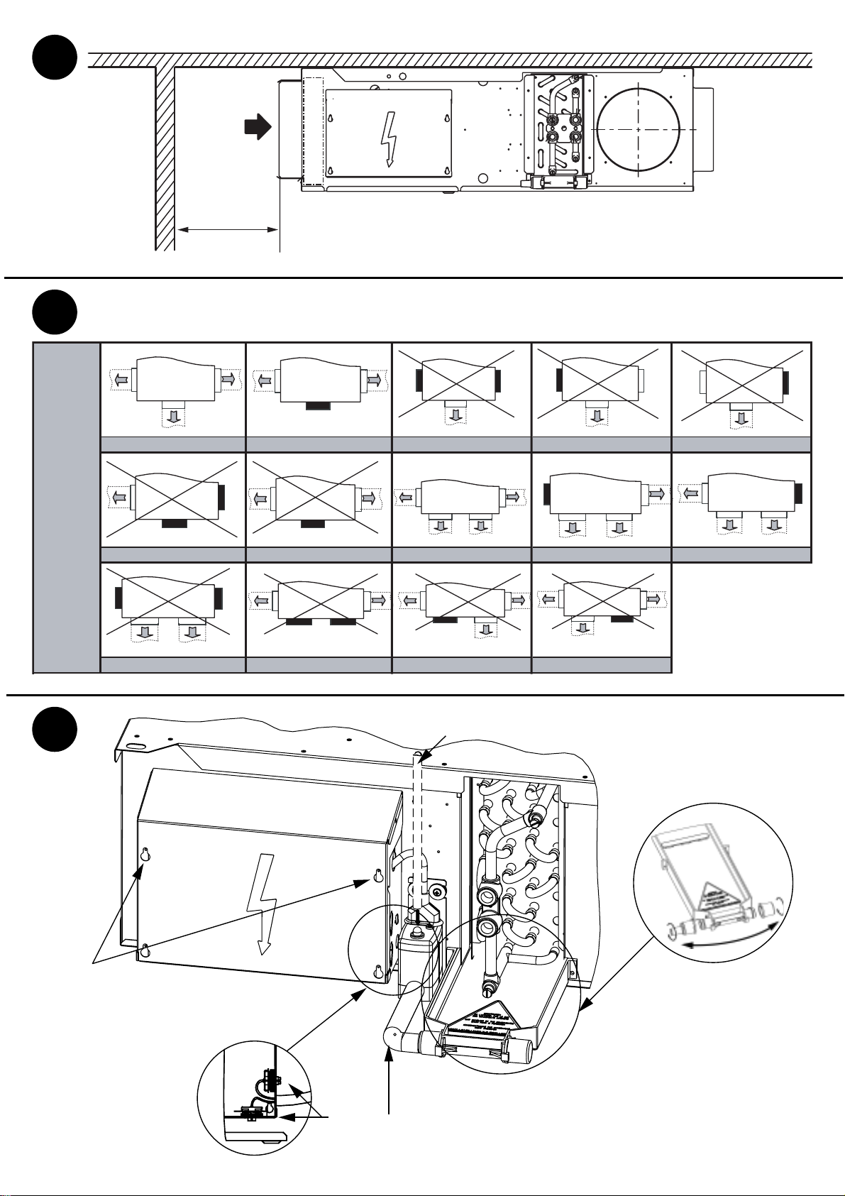
Description de l’appareil
(Fig.1)
1: Panneau d'accès GMV et filtre
2: Manchons de raccordements batterie
3: Purgeurs d'air batterie
4: Bac d'évacuation des condensats
5: Boîtier électrique métallique
6: Filtre air
7: Entrée prédécoupée Air Neuf Traité
8:Trous oblongs de fixation ∅12x 30mm
9: Suspension élastique (accessoire)
Modèles (Fig.2)
L'UTA COMPACT se présente sous quatre
modèles standards :
I: Manchette tôle à l'aspiration et au refoulement
pour gaine rectangulaire
Y: Manchette tôle à l'aspiration pour gaine
rectangulaire + plénum de soufflage avec viroles
pour gaines circulaires
H: Plénum de reprise et de soufflage avec viroles
pour gaines circulaires
U: Plénum de reprise et de soufflage avec une
virole latérale pour gaine circulaire
Réception de l’appareil
L'appareil est livré étiqueté sur l'emballage avec
toutes les caractéristiques de l'appareil (type,
modèle, numéro SO...) vous permettant de
l'identifier.
Chaque appareil possède une plaque signalétique
avec les références du produit à rappeler dans
toute correspondance.
A la réception des colis, le contrôle de l'état de la
marchandise est de la responsabilité totale du
destinataire :
●Pour les manquants, le client doit mentionner le
nombre exact de colis reçus.
●En cas d'avaries sur les appareils, le client doit
décrire impérativement sur le récépissé les
dommages constatés en présence du livreur, et
signer le récépissé qu'après.
IMPORTANT : Ces remarques, conformément à
l'article 105 du Code du Commerce, doivent être
confirmées, par lettre recommandée, auprès du
transporteur, dans un délai de 3 jours ouvrables.
Les mentions "sous réserves" et "sous réserves de
déballage" n'ont aucune valeur. Le client doit
déballer la marchandise en présence du livreur.
Des réserves précises à la livraison sont
nécessaires.
Manutention
Attention : L'appareil doit être manutentionné avec
soins. Les chocs risquent de fausser le châssis et
de détériorer le groupe moto-ventilateur(s).
L'appareil doit être levé de préférence par les trous
de fixation. Il est possible d'effectuer la mise en
place à l'aide d'un chariot élévateur en prenant soin
de ne pas endommager l'appareil.
Mise en place de l’appareil
L'appareil se place à l'intérieur du faux-plafond.
S'assurer que l'arrière de l'appareil, dans le cas de
reprise non gainée, est suffisamment éloigné de la
paroi (X=mini 250mm) (fig.3). L'appareil doit être
fixé au plafond à l'aide de tiges filetées (non
fournies), à fixer aux 4 trous oblongs avec des
suspensions élastiques (accessoire) (fig.1-9). Il doit
être parfaitement de niveau. Si une régulation avec
thermostat d'ambiance est prévue, ne pas l'exposer
au soleil, ni derrière une porte, ni au dessus d'un
appareil dégageant de la chaleur mais plutôt sur
une cloison intérieure à 150 cm du sol.
Raccordements aérauliques
Suivre les recommandations sur l'équilibrage
aéraulique des appareils, et les possibilités
d'obturation des viroles de soufflage pour le modèle
Y selon les tailles (fig.4).
Débit maximum conseillé par virole :
- ∅200mm est de 400m3/h.
- ∅250mm est de 600m3/h.
Attention : Aucune viroles des modèles H et U ne
peuvent être obturées, ni au soufflage ni à
l'aspiration.
Raccordements hydrauliques
Les batteries sont équipées de manchons de
raccordement doubles (fig.6a) à taraudage
"femelle", de purgeur d'air et de vidange.
Pour installer une vanne de régulation à portée
plate, un raccord CIAT (fig.6b) est nécessaire. Ces
raccords hydrauliques CIAT sont équipés de
collerette pour maintenir le joint dans sa position
lors du serrage. Le tableau (fig.6d) indique la
préconisation CIAT des joints à utiliser.
Installation :
●Pour ne pas détériorer ce raccord ou la vanne
CIAT, ne pas appliquer un couple de serrage
supérieur à 3,5 daN.m. Bien respecter le sens de
montage de la vanne.
Sur ces vannes CIAT la circulation doit se faire de A
→AB (A étant raccordé côté batterie et AB côté
réseau hydraulique). La pression différentielle
maximale admissible sur nos vannes (ouvertes ou
fermées) est 100 kPa. CIAT préconise de ne pas
dépasser 60 kPa.
Recommandations hydrauliques :
●La conception des réseaux hydrauliques est un
facteur déterminant pour le bon fonctionnement de
l'installation.
FRANCAIS

9
Pour cela prévoyez des vannes de vidange bien
placées et en nombre suffisant, des pots à boue,
des purges correctement installées en position
haute du circuit, des tés d'équilibrage sur chaque
unité terminale et des vannes de décharge si
nécessaire.
●Filtration : Il est nécessaire de prévoir un
système de filtration efficace (préconisée à 0.5 mm)
ur l'alimentation en eau et sur les eaux de retour.
●Rinçage : Il est impératif de réaliser un rinçage
complet de l'installation et de traiter l'eau de
manière à éviter l'encrassement du circuit.
Pendant le rinçage du circuit la vanne de votre
appareil doit être ouverte pour éviter toute
accumulation de boues et d'impuretés dans la
batterie :
- Vannes thermiques : le moteur de vanne doit
être enlevé. N'oubliez pas de le replacer après la
mise en eau et le rinçage.
- Vannes 3 Points : L'ouverture de la vanne se fait
manuellement et hors tension avec une clé Allen de
3 mm.
●Mise en eau : Purgez les batteries lors de la mise
en service.
●Recommandation de fonctionnement :Pour les
vannes équipées de moteurs thermiques, veiller à
ce que l'ambiance environnante du moteur de
vanne ne dépasse pas 50°C pour éviter tout risque
d'ouverture intempestive. Risque à prendre en
compte notamment pour les appareils en espace
confiné (ex : appareils installées dans un faux-
plafond).
Ciat décline toute responsabilité en cas de
détérioration des vannes due à une erreur de
conception du réseau d'alimentation
hydraulique ou d'une erreur de mise en service.
Afin d'éviter tout risque de condensation en
fonctionnement avec de l'eau glacée, il sera
nécessaire de calorifuger les tuyauteries sur toute
leur longueur en s'assurant que l'étanchéité soit
parfaite aux extrémités.
Pour des utilisations avec batterie eau et/ou batterie
électrique, nous déconseillons l'utilisation de tubes
en Polyéthylène Réticulé (PER) pour l'alimentation
des appareils. En cas de surchauffe de la batterie,
une élévation ponctuelle de la température de l'eau
est possible. Celle-ci peut faire chuter très
rapidement les caractéristiques du PER à proximité
de l'appareil jusqu'à l'éclatement de celui-ci. Nous
conseillons le raccordement hydraulique de la
batterie par l'intermédiaire de flexibles à tresse inox
(ou équivalent).
Bac des condensats
Un bac plastique incliné sans rétention d'eau
équipe l'UTA COMPACT. Ce bac est équipé d'une
douille de raccordement, et d'un bouchon (fig.5).
L'eau condensée est évacuée par la douille aux
diamètres : 15, 16 ou 28 mm extérieurs, un 4ème
raccordement à 22mm est disponible en retirant
celle-ci. Le raccordement peut s'effectuer par
l'avant ou l'arrière du bac par l'échange entre les 2
éléments (fig.5d). Dans le cas où le raccordement
s'effectue vers l'arrière de l'appareil, le tuyau
d'évacuation passera devant le boîtier électrique,
seules les 2 vis supérieures seront utilisables pour
refermer le capot (fig.5c).
La canalisation d'évacuation (fig.5a) peut-être
indépendante pour chaque appareil ou raccordée à
une tuyauterie principale d'évacuation. Utiliser un
tube d'évacuation transparent et/ou rigide (fig.5b)
pour une pente de 1 cm/m minimum, avec un
dénivelé constant tout le long du parcours. Prévoir
un siphon d'au moins 5 cm pour éviter tout
refoulement de gaz ou d'odeurs désagréables.
Assemblage pompe de
relevage
Une pompe de relevage peut équiper l'UTA
COMPACT . Les caractéristiques techniques sont :
10W, débit maximum de 8l/h, refoulement
maximum 6m.
Connecter un tuyau d'évacuation transparent non
fourni de diamètre 6mm intérieur (fig.5b) entre le
refoulement de la pompe et le conduit d'eau usée.
Attention, ce tuyau ne doit pas être pincé ou en
contact avec l'appareil ou autre élément externe.
Câbler suivant le schéma joint.
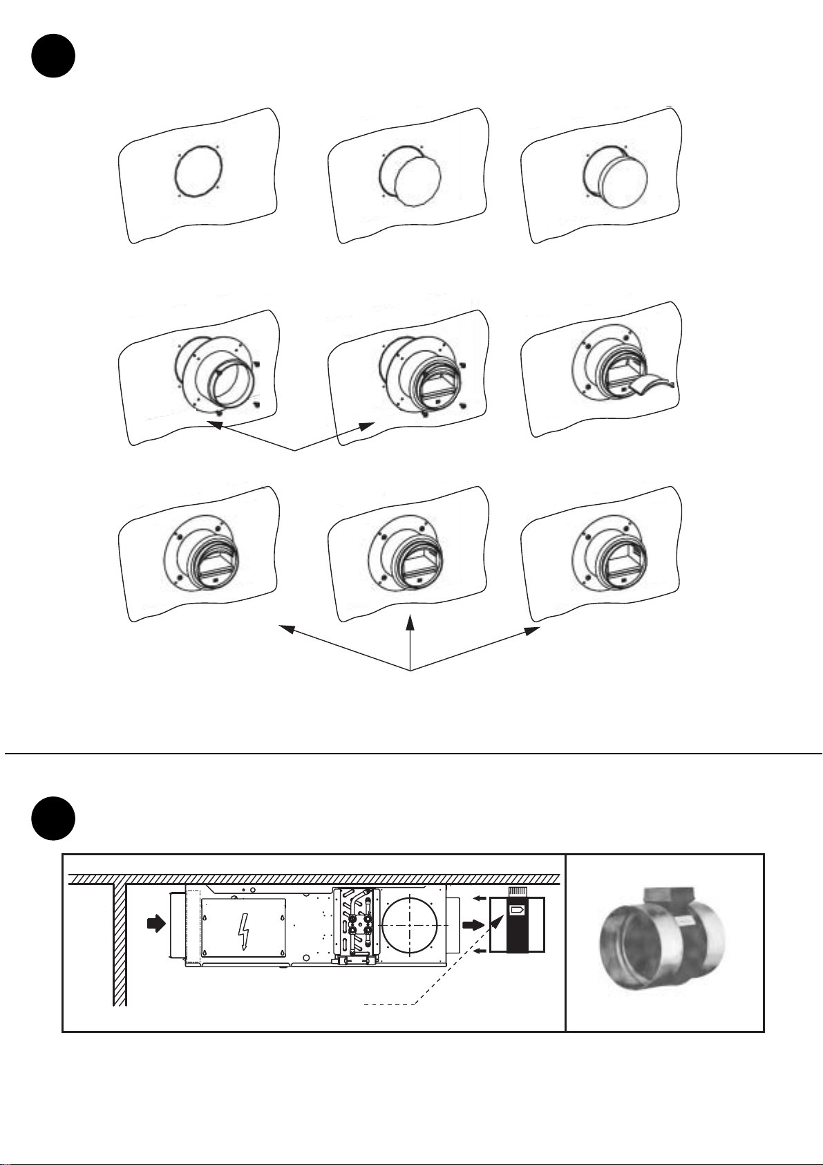
Montage virole air neuf avec
ou sans régulateur de débit
(fig.7)
7a Retirer la rondelle de tôle prédécoupée en
coupant les points d'attache.
7b Découper l'isolant suivant le contour de la
prédécoupe et en maintenant la mousse pour éviter
son décollage.
7c Fixer la virole avec ou sans régulateur à l'aide
des 4 vis fournies.
7d Retirer ou non le nombre de cales nécessaire
pour l'obtention du débit souhaité. La plage des
débits est décrite sur l'étiquette située sur la virole.
7e 2 cales correspondent au débit minimal, 1 cale
au débit moyen, et aucune cale au débit maximum
Afin d'obtenir le débit souhaité, le différentiel de
pression doit être compris entre 50 & 100 Pa.Veiller
à respecter la position BAS du régulateur.
Nota : Il est conseillé de travailler avec un taux d'air
neuf<20%.
Mise en place du registre
motorisé (fig.8)
Pour fixer le registre motorisé (fig.8), emboîter celui-
ci en force dans la manchette. Afin d'éviter de
déboîter le registre lors de l'installation du réseau
de diffusion, nous préconisons de poser une vis de
maintien entre les deux éléments. Bien veiller à
respecter le sens de l'air du registre (fig.8a).

10
Raccordements électriques
Avant de raccorder l'appareil au réseau, s'assurer
que la tension est bien celle indiquée sur la plaque
signalétique de l'appareil (230/1/50Hz).
La mise à la terre de l'appareil est impérative.Notre
responsabilité ne saurait être engagée en cas
d'accidents consécutifs à une mise à la terre
incorrecte ou inexistante.Toujours se conformer au
schéma électrique joint avec l'appareil.
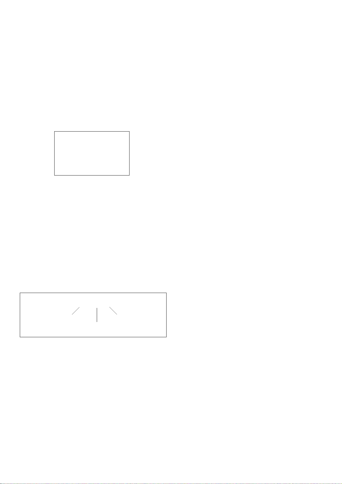
Pour des applications client, le schéma électrique
est à concevoir à partir des schémas génériques :
- Câblage de l'appareil en configuration 2 Tubes ou
4 Tubes (fig.13).
- Câblage de l'appareil en configuration 2T +
Electrique avec 1 ou 2 résistances (fig.14).
CIAT préconise l'utilisation d'une régulation de
l'appareil sur l'eau (active sur la ou les vannes(s)) et
la batterie électrique.
Attention : Les fils NOIR, BLEU et ROUGE
correspondant aux 3 vitesses ne doivent jamais
être reliés entre eux (bornes 2, 3 & 4).Pour accéder
au bornier, dévisser sans les retirer les vis du
boîtier électrique et soulever le capot à l'aide des
trous oblongs (fig.5c).
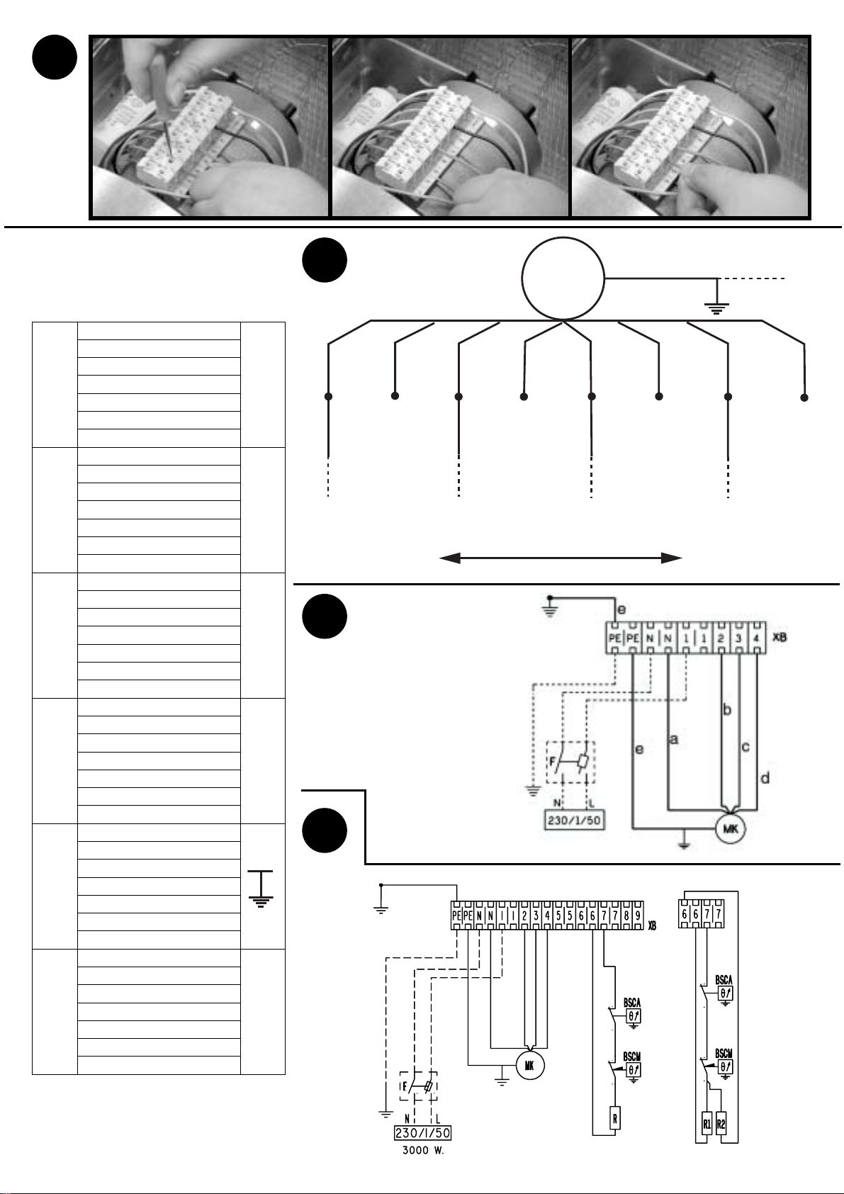
Modification du câblage électrique moteur :
Avant toute intervention à l'intérieur de l'appareil,
mettre l'appareil hors tension en coupant
l'alimentation électrique. L'unité terminale dispose
d'un moteur à 7 vitesses dont 3 sont précâblées en
usine.La figure 12 est un des exemples de câblage,
ici en 2-4-6 :
Pour modifier ce câblage usine, il vous suffit à l'aide
d'un petit tournevis à portée plate de retirer le fil
d'alimentation, après la mise hors tension (fig.11).
Puis de sélectionner le repère moteur désiré et de
clipser simplement à la main ce fil d'alimentation.
Instructions générales relatives à la sécurité
pour les appareils équipés de résistances
électriques :
- Asservissement au ventilateur : la batterie
électrique (1 ou 2 résistances) doit être
obligatoirement asservie au ventilateur. Tout arrêt
volontaire ou intempestif du groupe moto-
ventilateur doit entraîner impérativement la coupure
de l'alimentation des résistances électriques.
- Pour un bon fonctionnement eau chaude +
résistances électriques, seuls des régimes basse
température sont recommandés afin d'assurer un
bon fonctionnement de nos sécurités.
- La protection contre la surchauffe accidentelle des
appareils équipés de résistances est assurée par 2
thermostats limiteur de température (fig.5e). Le
réarmement éventuel des thermostats ne sera
effectué qu'après avoir recherché les causes de la
surchauffe ayant provoqué un déclenchement de
celui-ci. :
- Mise sous tension sans ventilation.
- Colmatage partiel du filtre.
- Régulation arrêtant simultanément la batterie et le
ventilateur.
Attention : Ne jamais raccorder plusieurs de nos
moteurs ventilo-convecteur en parallèle.
Maintenance appareil
Un entretien périodique entre les saisons de
chauffe et de rafraîchissement est à prévoir,
notamment pour les éléments subissant un
encrassement : filtre, bac des condensats,
batterie, pompe des condensats …
Avant toute intervention sur l'appareil, couper
l'alimentation électrique.
Entretien filtre d'air
Le filtre (fig.9a) est indispensable pour le bon
fonctionnement de l'appareil sous peine de
colmatage de la batterie d'échange.
Nous préconisons son échange entre chaque
saison de fonctionnement. Dans le cas d'une
maintenance plus rapprochée, le filtre peut être
nettoyé par aspiration, dans le sens inverse du
passage de l'air.
Retirer celui-ci en libérant le panneau inférieur à
l'aide des deux loquets "1/4 de tour" (fig.9b).
Examiner régulièrement l'aspect du filtre afin de
définir la périodicité du nettoyage qui est très
variable suivant la nature des locaux et les
conditions d'installation.
Entretien batterie d'échange
L'état de propreté de la batterie est un facteur
déterminant pour le bon rendement de l'appareil.Le
nettoyage de la batterie peut se faire à l'aide d'un
aspirateur.
Si besoin de démonter la batterie :
- Déconnecter la batterie eau du circuit
d'alimentation hydraulique
- Déconnecter l'évacuation des condensats.
- Dévisser les 2 vis du bac des condensats
(fig.10a).
- Dévisser les 4 vis de la batterie (fig.10b).
- Tirer vers soi l'ensemble batterie + bac des
condensats.
Légende :
GV : Grande vitesse
MV : Moyenne vitesse
PV : Petite vitesse
COM : Commun
2 4 6
Grande vitesse Petite vitesse
Moyenne vitesse

11
Remplacement batterie
électrique
Pour le bon fonctionnement de l'appareil, n'utiliser
que des pièces d'origine CIAT :
- Déconnecter les 2 fils de la résistance dans le
boîtier électrique, et les sortir de la gaine de
protection.
- Sortir la résistance du bloc aileté de la batterie
eau à l'aide d'une pince, en veillant à ne pas
détériorer les fils.
- Avant de remettre une résistance électrique,
s'assurer du bon état de celle-ci et veiller à ce
qu'elle soit parfaitement rectiligne afin de coulisser
librement dans le bloc aileté de la batterie.
Maintenance
groupe moto-ventilateur
Principe de démontage du groupe
moto-ventilateur (fig.10) :
- Enlever le panneau inférieur à l'aide des 2 loquets
"1/4 de tour" (fig.10c).
- Déconnecter le bornier électrique après que
l'appareil soit mis hors tension
- Dévisser et retirer uniquement les 2 vis inférieur
du groupe (fig.10d).
- Tirer le GMV par le bas pour le libérer des 2 autres
vis de maintien.
- Sortir le GMV par le dessous.
Faire l'opération inverse pour le remontage.
De temps en temps vérifier l'état de propreté des
turbines et du moteur ; si nécessaire, les nettoyer à
l'aide d'un aspirateur en prenant soin de ne pas les
endommager.
Le moteur électrique ne nécessite aucun entretien
particulier.
Entretien bac des condensats
Le bac des condensats sans rétention d'eau doit
rester propre. Un nettoyage complet du bac
plastique et de ses douilles peut se faire à l'aide de
produits détergents à l'eau non abrasifs. Ce
nettoyage peut s'effectuer sur la partie extérieure,
ou en retirant complètement le bac de l'appareil.
Essais et garantie
Tous nos appareils sont essayés et éprouvés avant
expédition.
Ils sont garantis contre tous vices de fabrication,
mais notre responsabilité ne saurait être engagée
en cas de corrosion quelconque. Les moteurs ne
sont pas garantis en cas d'erreur de branchement
électrique, d'une mauvaise protection ou d'une
utilisation sans filtre d'air.
Notre garantie couvre les moteurs dans le cas de la
garantie de notre fournisseur.
A aucun moment, l'installateur ne doit intervenir sur
le moteur. Dans le cas contraire, il perdrait le
bénéfice de la garantie éventuelle.
CIAT est en conformité avec le marquage CE,
autorisant une libre circulation de ses appareils sur
l'ensemble du territoire de l'Union Européenne. Ce
marquage est un gage de sécurité et de protection
des personnes.
. . . . . . . . . . . . . . . . . . . . . . . . . . . . . . . . . . . . . . . . . . . . . . . . . . . . . . . . . . . . . . . . . . . . . . . . . . . . . . . . . . . . . . . . . . . . . . . . . . . . .
. . . . . . . . . . . . . . . . . . . . . . . . . . . . . . . . . . . . . . . . . . . . . . . . . . . . . . . . . . . . . . . . . . . . . . . . . . . . . . . . . . . . . . . . . . . . . . . . . . . . .
. . . . . . . . . . . . . . . . . . . . . . . . . . . . . . . . . . . . . . . . . . . . . . . . . . . . . . . . . . . . . . . . . . . . . . . . . . . . . . . . . . . . . . . . . . . . . . . . . . . . .
. . . . . . . . . . . . . . . . . . . . . . . . . . . . . . . . . . . . . . . . . . . . . . . . . . . . . . . . . . . . . . . . . . . . . . . . . . . . . . . . . . . . . . . . . . . . . . . . . . . . .
. . . . . . . . . . . . . . . . . . . . . . . . . . . . . . . . . . . . . . . . . . . . . . . . . . . . . . . . . . . . . . . . . . . . . . . . . . . . . . . . . . . . . . . . . . . . . . . . . . . . .
. . . . . . . . . . . . . . . . . . . . . . . . . . . . . . . . . . . . . . . . . . . . . . . . . . . . . . . . . . . . . . . . . . . . . . . . . . . . . . . . . . . . . . . . . . . . . . . . . . . . .
. . . . . . . . . . . . . . . . . . . . . . . . . . . . . . . . . . . . . . . . . . . . . . . . . . . . . . . . . . . . . . . . . . . . . . . . . . . . . . . . . . . . . . . . . . . . . . . . . . . . .
. . . . . . . . . . . . . . . . . . . . . . . . . . . . . . . . . . . . . . . . . . . . . . . . . . . . . . . . . . . . . . . . . . . . . . . . . . . . . . . . . . . . . . . . . . . . . . . . . . . . .
. . . . . . . . . . . . . . . . . . . . . . . . . . . . . . . . . . . . . . . . . . . . . . . . . . . . . . . . . . . . . . . . . . . . . . . . . . . . . . . . . . . . . . . . . . . . . . . . . . . . .
. . . . . . . . . . . . . . . . . . . . . . . . . . . . . . . . . . . . . . . . . . . . . . . . . . . . . . . . . . . . . . . . . . . . . . . . . . . . . . . . . . . . . . . . . . . . . . . . . . . . .
. . . . . . . . . . . . . . . . . . . . . . . . . . . . . . . . . . . . . . . . . . . . . . . . . . . . . . . . . . . . . . . . . . . . . . . . . . . . . . . . . . . . . . . . . . . . . . . . . . . . .
. . . . . . . . . . . . . . . . . . . . . . . . . . . . . . . . . . . . . . . . . . . . . . . . . . . . . . . . . . . . . . . . . . . . . . . . . . . . . . . . . . . . . . . . . . . . . . . . . . . . .
. . . . . . . . . . . . . . . . . . . . . . . . . . . . . . . . . . . . . . . . . . . . . . . . . . . . . . . . . . . . . . . . . . . . . . . . . . . . . . . . . . . . . . . . . . . . . . . . . . . . .
. . . . . . . . . . . . . . . . . . . . . . . . . . . . . . . . . . . . . . . . . . . . . . . . . . . . . . . . . . . . . . . . . . . . . . . . . . . . . . . . . . . . . . . . . . . . . . . . . . . . .
. . . . . . . . . . . . . . . . . . . . . . . . . . . . . . . . . . . . . . . . . . . . . . . . . . . . . . . . . . . . . . . . . . . . . . . . . . . . . . . . . . . . . . . . . . . . . . . . . . . . .
. . . . . . . . . . . . . . . . . . . . . . . . . . . . . . . . . . . . . . . . . . . . . . . . . . . . . . . . . . . . . . . . . . . . . . . . . . . . . . . . . . . . . . . . . . . . . . . . . . . . .
. . . . . . . . . . . . . . . . . . . . . . . . . . . . . . . . . . . . . . . . . . . . . . . . . . . . . . . . . . . . . . . . . . . . . . . . . . . . . . . . . . . . . . . . . . . . . . . . . . . . .
. . . . . . . . . . . . . . . . . . . . . . . . . . . . . . . . . . . . . . . . . . . . . . . . . . . . . . . . . . . . . . . . . . . . . . . . . . . . . . . . . . . . . . . . . . . . . . . . . . . . .
. . . . . . . . . . . . . . . . . . . . . . . . . . . . . . . . . . . . . . . . . . . . . . . . . . . . . . . . . . . . . . . . . . . . . . . . . . . . . . . . . . . . . . . . . . . . . . . . . . . . .
. . . . . . . . . . . . . . . . . . . . . . . . . . . . . . . . . . . . . . . . . . . . . . . . . . . . . . . . . . . . . . . . . . . . . . . . . . . . . . . . . . . . . . . . . . . . . . . . . . . . .
. . . . . . . . . . . . . . . . . . . . . . . . . . . . . . . . . . . . . . . . . . . . . . . . . . . . . . . . . . . . . . . . . . . . . . . . . . . . . . . . . . . . . . . . . . . . . . . . . . . . .
. . . . . . . . . . . . . . . . . . . . . . . . . . . . . . . . . . . . . . . . . . . . . . . . . . . . . . . . . . . . . . . . . . . . . . . . . . . . . . . . . . . . . . . . . . . . . . . . . . . . .
. . . . . . . . . . . . . . . . . . . . . . . . . . . . . . . . . . . . . . . . . . . . . . . . . . . . . . . . . . . . . . . . . . . . . . . . . . . . . . . . . . . . . . . . . . . . . . . . . . . . .

12
CIAT company thanks you for the purchase of a
UTA COMPACT which, we hope, will give you entire
satisfaction. To guarantee its working, connections
(electric, fluids,…) must comply with state-of-the-art
installation rules and country regulations. The
maintenace of you terminal unit will take into
account the recommendations mentionned in the
present brochure.
UTA COMPACT unit
description (Fig.1)
1: Fan assembly and filter access panel
2: Coil hydraulic connections
3: Coil air vents
4: Drain pan
5: Metallic electrical box
6: Air filter
7: Pre-cut fresh air inlet
8: Fixations holes ∅12x30mm
9: Elastic dampers (accessory)
Models (Fig.2)
UTA COMPACT in four standard models :
I: Steel sleeve on inlet and outlet for rectangular
ducts.
Y: Steel sleeve on inlet for rectangular duct +
discharge plenum with flanges for circular ducts.
H:Return and discharge air plenum with flanges for
circular ducts.
U: Return and discharge air plenum with side
flanges for circular duct.
Unit Réception
The unit is supplied in labelled cardboard packaging
with all the unit's characteristics (type, model, SO
number,...) enabling you to identify it. Each unit has
an identification plate marked with an identification
number to be given in all correspondence.
When the packages are received, the inspection of
the condition of the goods at arrival is the recipient's
entire responsibility :
●For shortages, the customer must mention the
exact number of packages received.
●In the event of defects on the units, the customer
must describe the damage observed on the receipt
in the presence of the delivery person, and only
sign the receipt after having done this.
IMPORTANT : These remarks, in compliance with
article 105 of the French trade code, must be
confirmed by registered letter to the transport
operator within 3 working days. The terms
"reservations" and "subject to unpacking" are not
valid. The customer must unpack the goods in the
presence of the delivery person. Specific
reservations at delivery are required.
Handling
Caution :The unit must be handled with care.With
shocks there is a risk of twisting the frame and
damaging the fan-motor assembly. If possible the
unit should be lifted using the fixation holes. If this
lifting means cannot be used, the operation can be
carried out using a fork-lift.
Putting the unit in place
The unit should be installed inside the false ceilling.
If the unit isn't ducted to the inlet, make sure to
respect a distance between the wall and the rear of
the unit (X=250 mm mini) (fig.3).
The unit should be fixed to the ceiling using
threaded rods (not supplied), use the 4 fixation
holes with elastic dampers (accessory) (fig.1-9).
Check the unit with a spirit level.
If a control with wall thermostat is used, do not
expose it to the sun, behind a door, nor above an
apparatus discharging heat, but rather on an interior
wall to 150 cm height.
Aeraulic connections
Follow the recommendations relating to the aeraulic
balancing of the units and sealing possibilities of Y
model's discharge spigots, according to sizes
(fig.4).
Recommanded air flow for outlet :
- ∅200mm ➙400m3/h.
- ∅250mm ➙600m3/h.
Caution : Spigots on H or U models must not be
blocked, neither on the discharge nor on the intake
sides.
hydraulic connections
The coils are equipped with monobloc "female"
threaded double hydraulic connections (fig.6a), air
vent and drain.
To fit a control valve with a flat seal, a CIAT
connector is necessary (fig.6b).The CIAT hydraulic
connectors are equipped with a flange to maintain
the gasket in position during tightening. The table
(fig.6d) gives the CIAT recommendation concerning
the joints.
Installation :
●In order not to deteriorate this connector or the
CIAT valve, do not apply a torque superior to 3.5
daN.m. Respect the valve assembly direction.
On these CIAT valves, the circulation must occur
from A →AB (A being connected on the coil side
and AB on the hydraulic pipework). The maximal
admissible differential pressure on our valves (open
or closed) is 100 kPa. CIAT recommends not to
overpass 60 kPa.
ENGLISH

13
Recommandations hydrauliques :
●The hydraulic pipeworks design is a determining
factor to ensure a correct plant operation. Plan a
sufficient number of properly positioned draining
valves, mud pots, drains installed at the upper part
of the circuit, balancing tees on each terminal unit
and discharge valves if necessary.
●Filtration : Water supply and return waters must
be fitted with an efficient filtration system
(recommended at 0.5 mm).
●Rincing : it is imperative to carry out a complete
rinsing of the installation and to treat the water in
order to avoid circuit fouling.
While rinsing the circuit, the valve of your unit must
be open so as to avoid accumulation of muds and
impurities in the coil :
- Termal valves : Thermal valves : the valve motor
must be withdrawn. Do not forget to reposition it
after water filling and rinsing.
- 3-point valves :The unit must be switched off while
opening the valve manually with a 3 mm Allen
wrench.
●Water filling : Drain the coils when starting the
unit
●Operating recommendations : for valves
equipped with thermal motors, make sure that the
ambient temperature of the valve motor does not
overpass 50°C, in order to avoid untimely opening
risk. This risk is to be taken into account, namely for
units located in a confined space (ex :units installed
in a false ceiling).
CIAT is not held responsible in case of valve
deterioration due to hydraulic supply pipework
design error or commissioning error.
To avoid any risk of condensation when using
chilled water, it will be necessary to insulate the
pipework, ensuring that it is vapour sealed.
For use with 2-pipe/2-wire coil, we advise installers
against the use of PER piping for connections. In
case of overheating, an important rise of the
temperature is possible. This one can deteriorate
characteristics of the PER up to the blow-out. We
advise to connect the coil by means of a flexible
with a stainless stell treillis fence (or equivalent).
Drain pan
A inclined plastic drain pan without water retention
equipped the UTA COMPACT, with a connection
nut and a cork (fig.5). Condensates are evacuated
by the nut with available diameters : external 15, 16
or 28 mm, a fourth one with a 22 mm diameter is
available by withdrawing it.Connection can be done
by the front or the rear of the drain pan, by
exchange of the both elements (fig.5d). In case of
connection by the rear, the condensate piping will
cross in front of the electrical box, only upper
screws will be used to close the box (fig.5c).
The drainage pipework (fig.5a) can be separate for
each unit or connected to a main drain. Use a
transparent & rigid evacuation tube (fig.5b), with a
minimum slope of 1 cm/m, with a constant
difference in level along its path.Provide a siphon of
at least 5 cm to prevent any discharge of gas or
unpleasant odours.
Drain pump assembling
A drain pump can equip terminal unit UTA
COMPACT. Technical characteristics are : 10W,
maximum flow rate 8l/h, maximum water height 6m.
Connect a 6 mm internal diameter transparent
piping not supplied (fig.5b) between the pump outlet
and the drainage pipework. Be careful, this piping
musn't be pinched or in contact with the fan coil unit
or with external element.
Fresh air sleeve assembling
with or without flow rate
controller (fig.7)
7a Remove the pre-cut hole by cutting the links
points.
7b Cut the insulation foam following the outline, and
maintain the foam to avoid to unstick it.
7c Fit the sleeve, with or without the air flow rate
controller, with help of the 4 screws delivered.
7d Remove the necessary number of strut for the
right air flow rate. The flow rate range is described
on the sticker of the equipment.
7e 2 struts correspond to a minimal flow rate,1 strut
to the medium flow rate and none to the maximal
one.
To get the desired air flow rate, the pressure
differentiate must be between 50 & 100 Pa. Be care
to respect the right position ("BAS" below).
Note :It is recommended to operate with a fresh air
flow rate < 20%.
Installation of the motorized
register (fig.8)
To attach the motorized register (fig.8), engage it in
the trunking by force. To avoid disengaging the
register when installing the distribution network, we
recommend to installing a retaining screw between
the two composents.Make sure that the register air
is oriented in the right direction (fig.8a).

14
Electrical wiring
Before connecting the unit to the mains, make sure
that the voltage is the same as that indicated on the
unit identification plate (230V - 1ph - 50Hz). The
connections to the mains should comply with the
applicable installation regulations.The unit must be
earthed. We cannot be held responsible for
accidents following incorrect or non-existent
earthing. The wiring must respect the supplied
electrical drawing.
For customer applications, the electrical diagram is
to be drawn up from the generic diagrams provided:
- Wiring of the unit in 2-pipe or 4-pipe system
(fig.13)
- Wiring of the unit in 2-pipe + Electric with 1 or 2
elements (fig.14).
CIAT recommends use of a water control for the
appliance (acting on the valve(s) and the electric
coil).
Caution: The BLACK, BLUE and RED wires
corresponding of the 3 speeds must never be
interconnected (switchs 2, 3 & 4). To access to
electrical connections, unscrew the two screws on
the electrical box, and raise the casing with help of
fixation holes (fig.5c).
Modification of electrical wiring :
Before removing the body and performing any
intervention inside the unit, switch off unit. The
terminal unit is equipped with 7-speed motor, for
which 3 speeds are pre-wired in the factory.
Diagram 12 is one of the wiring examples, This one
is in 2-4-6 :
To modify the wiring, simply remove the power
supply wire using a small flat screwdriver, after
switching off the unit (fig.11). Then select the
required motor mark and simply clip on the power
supply wire by hand without using the screwdriver.
General safety instructions for units equipped
with electric resistances:
- Fan control : The electric heater (1 or 2 elements)
must be controlled by the fan. Any voluntary or
untimely stoppage of the ventilation unit must cause
the power supply to the electric resistances to be
cut off.
- For a correct operation in heating + electric
resistances, only the low temperature modes are
recommended in order to ensure a correct
operation of our safety.
- The protection against accidental overheating of
the units equipped with resistances is ensured by 2
temperature limiter thermostats (fig.5e). The
possible thermostats reset will be carried out only
after having found the overheating origin that
causes its triggering :
- coil switched on without ventilation,
- partial clogging of filter,
- control system stopping the coil and the fan
simultaneously.
Careful : Our fan coil motors must never be
connected in parallel.
Unit servicing
A periodic servicing between each cooling and
heating seasons is to schedule, particularly for
elements favourable to dirtying : filter, drain
pan, coil, condensate pump …
Before removing the body and performing any
intervention inside the unit, switch off unit by
switching off the electricity supply.
Air filter servicing
The filter (fig.9a) is indispensable for correct
operation; if its operation is degraded, the
exchanger coil can become clogged.
We preconise its exchange between each working
season.In case of a monthly servicing schedule the
filter should be cleaned by vacuuming in the
opposite direction to the air flow.
Withdrawal is made by releasing the lower panel,
using the two ¼ turn latches (fig 9b).
The interval between cleanings can vary
considerably depending upon the nature of the
room and installation conditions.
Water coil servicing
The clean state of the coil is a positive factor for
proper output of the unit. The coil can be cleaned
with a vacuum cleaner.
If the coil has to be dismantled :
- Disconnect the water coil from the hydraulic
supply circuit
- Disconnect the condensates drainage
- Loosen the 2 drain pan screws (fig 10a)
- Loosen the 4 coil screws (fig 10.b)
- Pull toward yourself the coil + drain pan assembly
Legend :
GV : High speed
MV : Medium speed
PV : Low speed
COM : Common
2 4 6
High speed Low speed
Medium speed

15
Electric coil replacement
To ensure the good running of the unit, use only
CIAT spare parts :
- Disconnect the 2 wires of the electric element, and
pull out them from the plastic duct.
- Remove the electric element from the water coil
with the help of tongs, avoiding to damage wires.
- Before repositionning a electric element, check
the correct state of its surface and ensure that it is
perfectly straight in order to slide freely inside the
finned water coil.
Fan assembly servicing
Dismantling principle of the fan motor assembly
(fig 10) :
- Release the lower panel by using the two ¼ turn
latches (fig 10c)
- Disconnect the electrical terminal block after the
unit has been switched off
- Loosen and withdraw only the two internal screws
of the unit (fig 10d)
- Pull the fan motor assembly downward in order to
release the 2 remaining withholding screws
- Remove the fan motor assembly through the
bottom.
To re-assemble, follow the directions in reverse
order.
From time to time check cleanliness of the fan and
motor ; if necessary clean with a vacuum cleaner
taking care not to cause damage.
The electrical motor does not require any particular
maintenance.
Drain pan servicing
The drain pan without water retention must stay
clean. A complete cleaning of the plastic drain pan
and its nuts may be done with a non abrasive lightly
soaped liquid.This cleaning can be done by outside
the unit, or after removing of the complete drain pan
(see Coil Servicing).
Periodically check that the condensate drain
openings are not blocked.
Guarantee & tests
All of our units are tested and approved before
shipping.
The guarantee covers manufacturing faults ; but we
cannot be held responsible for corrosion damage.
Motors are not guaranteed against faulty
connecting, poor protection or use without an air
filter.
Our guarantee coincides with that of the motor
supplier. The installer should never tamper with the
motor. If this occurs, any possible guarantee
benefits are lost.
CIAT complies with the CE mark, authorising the
free circulation of its units throughout the European
Union. This mark is a guarantee of personal safety
and protection.
. . . . . . . . . . . . . . . . . . . . . . . . . . . . . . . . . . . . . . . . . . . . . . . . . . . . . . . . . . . . . . . . . . . . . . . . . . . . . . . . . . . . . . . . . . . . . . . . . . . . .
. . . . . . . . . . . . . . . . . . . . . . . . . . . . . . . . . . . . . . . . . . . . . . . . . . . . . . . . . . . . . . . . . . . . . . . . . . . . . . . . . . . . . . . . . . . . . . . . . . . . .
. . . . . . . . . . . . . . . . . . . . . . . . . . . . . . . . . . . . . . . . . . . . . . . . . . . . . . . . . . . . . . . . . . . . . . . . . . . . . . . . . . . . . . . . . . . . . . . . . . . . .
. . . . . . . . . . . . . . . . . . . . . . . . . . . . . . . . . . . . . . . . . . . . . . . . . . . . . . . . . . . . . . . . . . . . . . . . . . . . . . . . . . . . . . . . . . . . . . . . . . . . .
. . . . . . . . . . . . . . . . . . . . . . . . . . . . . . . . . . . . . . . . . . . . . . . . . . . . . . . . . . . . . . . . . . . . . . . . . . . . . . . . . . . . . . . . . . . . . . . . . . . . .
. . . . . . . . . . . . . . . . . . . . . . . . . . . . . . . . . . . . . . . . . . . . . . . . . . . . . . . . . . . . . . . . . . . . . . . . . . . . . . . . . . . . . . . . . . . . . . . . . . . . .
. . . . . . . . . . . . . . . . . . . . . . . . . . . . . . . . . . . . . . . . . . . . . . . . . . . . . . . . . . . . . . . . . . . . . . . . . . . . . . . . . . . . . . . . . . . . . . . . . . . . .
. . . . . . . . . . . . . . . . . . . . . . . . . . . . . . . . . . . . . . . . . . . . . . . . . . . . . . . . . . . . . . . . . . . . . . . . . . . . . . . . . . . . . . . . . . . . . . . . . . . . .
. . . . . . . . . . . . . . . . . . . . . . . . . . . . . . . . . . . . . . . . . . . . . . . . . . . . . . . . . . . . . . . . . . . . . . . . . . . . . . . . . . . . . . . . . . . . . . . . . . . . .
. . . . . . . . . . . . . . . . . . . . . . . . . . . . . . . . . . . . . . . . . . . . . . . . . . . . . . . . . . . . . . . . . . . . . . . . . . . . . . . . . . . . . . . . . . . . . . . . . . . . .
. . . . . . . . . . . . . . . . . . . . . . . . . . . . . . . . . . . . . . . . . . . . . . . . . . . . . . . . . . . . . . . . . . . . . . . . . . . . . . . . . . . . . . . . . . . . . . . . . . . . .
. . . . . . . . . . . . . . . . . . . . . . . . . . . . . . . . . . . . . . . . . . . . . . . . . . . . . . . . . . . . . . . . . . . . . . . . . . . . . . . . . . . . . . . . . . . . . . . . . . . . .
. . . . . . . . . . . . . . . . . . . . . . . . . . . . . . . . . . . . . . . . . . . . . . . . . . . . . . . . . . . . . . . . . . . . . . . . . . . . . . . . . . . . . . . . . . . . . . . . . . . . .
. . . . . . . . . . . . . . . . . . . . . . . . . . . . . . . . . . . . . . . . . . . . . . . . . . . . . . . . . . . . . . . . . . . . . . . . . . . . . . . . . . . . . . . . . . . . . . . . . . . . .
. . . . . . . . . . . . . . . . . . . . . . . . . . . . . . . . . . . . . . . . . . . . . . . . . . . . . . . . . . . . . . . . . . . . . . . . . . . . . . . . . . . . . . . . . . . . . . . . . . . . .
. . . . . . . . . . . . . . . . . . . . . . . . . . . . . . . . . . . . . . . . . . . . . . . . . . . . . . . . . . . . . . . . . . . . . . . . . . . . . . . . . . . . . . . . . . . . . . . . . . . . .
. . . . . . . . . . . . . . . . . . . . . . . . . . . . . . . . . . . . . . . . . . . . . . . . . . . . . . . . . . . . . . . . . . . . . . . . . . . . . . . . . . . . . . . . . . . . . . . . . . . . .
. . . . . . . . . . . . . . . . . . . . . . . . . . . . . . . . . . . . . . . . . . . . . . . . . . . . . . . . . . . . . . . . . . . . . . . . . . . . . . . . . . . . . . . . . . . . . . . . . . . . .
. . . . . . . . . . . . . . . . . . . . . . . . . . . . . . . . . . . . . . . . . . . . . . . . . . . . . . . . . . . . . . . . . . . . . . . . . . . . . . . . . . . . . . . . . . . . . . . . . . . . .
. . . . . . . . . . . . . . . . . . . . . . . . . . . . . . . . . . . . . . . . . . . . . . . . . . . . . . . . . . . . . . . . . . . . . . . . . . . . . . . . . . . . . . . . . . . . . . . . . . . . .
. . . . . . . . . . . . . . . . . . . . . . . . . . . . . . . . . . . . . . . . . . . . . . . . . . . . . . . . . . . . . . . . . . . . . . . . . . . . . . . . . . . . . . . . . . . . . . . . . . . . .
. . . . . . . . . . . . . . . . . . . . . . . . . . . . . . . . . . . . . . . . . . . . . . . . . . . . . . . . . . . . . . . . . . . . . . . . . . . . . . . . . . . . . . . . . . . . . . . . . . . . .
. . . . . . . . . . . . . . . . . . . . . . . . . . . . . . . . . . . . . . . . . . . . . . . . . . . . . . . . . . . . . . . . . . . . . . . . . . . . . . . . . . . . . . . . . . . . . . . . . . . . .
. . . . . . . . . . . . . . . . . . . . . . . . . . . . . . . . . . . . . . . . . . . . . . . . . . . . . . . . . . . . . . . . . . . . . . . . . . . . . . . . . . . . . . . . . . . . . . . . . . . . .
. . . . . . . . . . . . . . . . . . . . . . . . . . . . . . . . . . . . . . . . . . . . . . . . . . . . . . . . . . . . . . . . . . . . . . . . . . . . . . . . . . . . . . . . . . . . . . . . . . . . .

16
CIAT dankt Ihnen einen UTA COMPACT gekauft zu
haben und hofft, dass er Ihnen volle Zufriendenheit
bringen wird. Um einen guten Betrieb zu
gewährleisten, müssen die Anschlüsse
(elektrische, hydraulische, …) vorschriftsmässig
und gemäss den im Installationsland
entsprechenden Normen installiert werden. Die in
der Broschüre angegebenen Anweisungen müssen
für die Wartung der UTA ebenfalls beachtet werden.
Gerätebeschreibung (Abb. 1)
1: Zugangspaneele zum Motor-Ventilator-Satzund
Luftfilter.
2: Register Anschlussmuffe
3: Entlüftungsventil des Registers
4: Kondensatwanne
5: Metall-Schaltkasten
6: Luftfilter
7:Vorgestanzte Frischlufteintritt
8: Befestigungs- Langlöcher ∅12 x 30mm
9: Schwingungsfreie Aufhängungen (Zubehör)
Modelle (Abb.2)
Der UTA OMPACT ist in 4 Modellen verfügbar :
I: Stahlstutzen am Ansaug und Ausblas für
Rechteckkanäle
Y: Stahlstutzen saugseitig für Rechteckkanäle +
Ausblasplenum mit Flansch für Rundkanäle.
H: Rückluft-und susblasplenum mit flansch für
Rundkanäle.
U: Seitliche Rückluf-und Ausblasplenum mit
Flansch für Rundkanäle.
Entgegennahme des Gerätes
Das Gerät wird in einer etikettierten Verpackung mit
allen Angaben (Typ, Modell, Bestellungs-
Nummer…) geliefert. Diese Angaben erlauben
Ihnen, das Gerät genau zu identifizieren.
Jedes Gerät besitzt ein Typenschild mit allen
Produktreferenzen, die bei jeder Korrespondenz
angegeben werden müssen.
Bei Entgegennahme der Pakete: die Kontrolle des
Materialzustands bei seiner Ankunft liegt unter
vollständiger Verantwortung des Empfängers :
●Für fehlendes Material, muss der Kunde die
genaue Anzahl der erhaltenen Pakete anführen.
●Im Fall von Transportschäden der Geräte, muss
der Kunde unbedingt, in Gegenwart vom
Lieferanten, die festgestellten Schäden auf der
Empfangsbescheinigung beschreiben und erst
anschliessend die Empfangsbescheinigung
unterschreiben.
WICHTIG : Diese Bemerkungen, gemäss Artikel
105 des "Code du Commerce", müssen durch ein
Einschreiben an den Spediteur innerhalb von 3
Werkstagen bestätigt werden. Die Vermerke "unter
Vorbehalt" und "unter Vorbehalt von Auspacken"
haben keine Gültigkeit.Der Kunde muss dieWare in
Gegenwart vom Lieferanten auspacken. Bei der
Lieferung sind genaue Vorbehalte notwendig.
Handhabung
Achtung : Das Gerät muss vorsichtig behandelt
werden. Durch Schlageinwirkung kann das
Gehäuse beschädigt und die Motor-
Ventilatorgruppe zerstört werden. Das Gerät sollte
möglichst an den Befestigungslöchern angehoben
werden. Es ist möglich das Gerät mittels eines
Gabelstaplers zu bewegen.
Installation des Gerätes
Das Gerät wird innerhalb der Zwischendecke
installiert.
Falls die Rückluft ohne Luftkanal erfolgt, sollten Sie
sich versichern, dass das Gerät weit genug von der
Wand steht (X=250 mm minimum) (Abb.3).
Das Gerät muss an der Decke mittels
Schraubenbolzen (nicht im Lieferumfang) befestigt
werden. Dafür werden wir mit schwingungsfreien
Aufhängungen (Zubehör) (Abb.1-9) die 4
Langlöcher verwenden.
Falls ein Raumthermostat vorgesehen ist, darf es
keinem Sonnenlicht ausgesetzt sein, nicht hinter
einer Tür und nicht über einem Gerät installiert
werden, welches Wärme abgibt, sondern am
besten an einer Innentrennwand mit 150 cm vom
Boden.
Lufseitige anschlüsse
Beachten Sie bitte die Vorschriften für den
lufttechnischen Ausgleichung und die
Verschlussmöglichkeiten der Öffnungen in
Abhängigkeit der Baugrösse für die Modell Y
(Abb.4).
Der maximale zulässige Volumenstrom pro ∅
200mm Anschluss beträgt 400 m3/h und 250mm /
600 m3/h.
Achtung : Bei den Modellen H und U dürfen keine
Öffnungen an der Rückluft- oder Zuluftseite
verschlossen werden.
Wasseranschlüsse
Die Register sind mit Doppel-Anschlussmuffen
(Abb.6a) mit Innengewinde, Entlüftungshahn und
Ablass versehen.
Um Regelventile mit Flachkopf anzuschliessen, ist
ein CIAT-Anschluss (Abb. 6b) notwendig.
Die CIAT Wasseranschlüsse sind mit einem
Flansch versehen, damit die Dichtung während des
Festspannens in ihrer Position bleibt.
In der Tabelle (Abb.6d) werden die von CIAT
empfohlenen Dichtungen aufgeführt.
Installation :
●Um eine Beschädigung des Anschlussblocks
oder des Ventils zu vermeiden, darf man die
Verbindungen mit einem Drehmoment von maximal
3,5 daN.m anziehen.Die Einbaurichtung derVentile
muss beachtet werden.
DEUTSCH

17
Bei den CIAT-Ventilen muss die Fliessrichtung des
Wassers von A →B sein (A ist auf der
Wärmeaustauscherseite). Der maximal erlaubte
Differenzdruck am Ventil (geöffnet oder
geschlossen) darf 100 kPa nicht überschreiten. Für
einen optimalen und geräuscharmen Betrieb raten
wir 60 kPa nicht zu überschritten.
Hydraulische Ratschläge :
●Die Auslegung des Wassernetzes ist ein
entscheidener Faktor für einen problemlosen
Betrieb. Dafür benötigen Sie gut positionierte und
ausreichend Entleerungsventile, Schalmmbehälter,
Entlüftungen an den höchsten Punkten der Anlage,
Regulierventile für jeden Klimakonvektor und
eventuell Ausgleichssventile.
●Filterung : es ist nötig ein wirksames
Filterungssysteme (0.5 mm) für die Vor- und
Rücklaufleitung vorzusehen.
●Spülen : um jede Kreislaufverschmutzung zu
vermeiden, ist ein komplettes Spülen der
Installation durchzuführen und eine
Wasseraufbereitung vorzusehen.
Während des Spülens des Kreisläufes, soll das
Ventil am Gerät offen sein, um jede Schlamm- und
Partikelanhäufung im Wärmeaustauscher zu
vermeiden :
- Thermische Ventile : der Ventilantrieb soll entfernt
sein. Nach der Wasserfüllung und dem Spülen
wiedermontieren.
- 3-Punkt-Ventile : die Ventilöffnung kann manuell
spannungslos mit Hilfe eines 3mm Imbusschlüssel
erfolgen.
●Wasserfüllung : Während der Inbetriebnahme
sollen die Wärmeaustauscher entlüftet werden.
●Betriebsempfehlung : Für die Ventile, die mit
elektrothermischen Antrieben ausgestattet sind, ist
darauf zu achten, daß die Umgebungstemp. des
Antriebes 50°C nicht überschreitet, um jedes
unangebrachte Öffnungsrisiko zu vermeiden.
Insbesondere für die Geräte in abgekapseltem
Raum zu berücksichtigen (z.B.: Geräte installiert in
einer Zwischendecke).
Ciat lehnt jede Gewährleistung bei
Verschlechterung der Ventile ab, die auf einen
Konzeptionsfehler des hydraulischen
Versorungsnetzes oder eines
Inbetriebnahmefehlers. zurückzuführen ist.
Um jegliche Kondensatbildung bei Betrieb mit
Kaltwasser zu verhindern, ist es erforderlich, die
Rohrleitungen in ihrer gesamten Länge mit
Wärmedämmung zu versehen, wobei
sicherzustellen ist, dass die Dichtheit an den Enden
gewährleistet ist.
Bei einer Verwendung mit Wasserregister und E-
Heizung raten wir von einer Verwendung eines
PER-Rohr für dieWasserversorgung der Geräte ab.
Bei Überhitzung der E-Heizung ist ein lokaler
Anstieg der Wassertemperatur möglich. Dieser
kann die Eigenschaften des PER neben dem Gerät
sehr schnell abfallen lassen und bis zu seinem
Platzen führen.Für die anderen Fälle empfehlen wir
den Wasseranschluss des Registers mittels
flexiblen Rohren aus Edelstahl (oder gleichwertig).
Kondensatwanne
Der UTA COMPACT ist mit einer geneigten
Kondensatwanne ohne Wasseransammlung
ausgerüstet, die ein Auschlussrohr und einen
Deckel enthalten (Abb.5).Das kondensierteWasser
wird mittels des Anschlussrohrs mit einem
Aussendurchmesser von 15, 16 oder 28 mm
abgeleitet. Ein vierter Anschlussdurchmesser von
22 mm ist auch möglich bei Entfernung dieser
Stutze. Der Kondensatleitungsanschluss kann nach
hinten oder nach vorne erfolgen durch Austausch
dieser 2 Elemente (Abb.5d). Im Fall eines
Anschlusses nach hinten, wird das Abflussrohr vor
dem Schaltkasten liegen ; nur die 2 oberen
Schrauben werden dann verwendbar sein, um den
Deckel zu befestigen (Abb.5c).
Das Ablassystem (Abb 5a) kann für jedes Gerät
separat oder an eine Hauptrohrleitung
angeschlossen sein. Benutzen Sie einen
durchsichtigen und/oder festen Ablasschlauch (Abb
5b) mit einem minimalen Gefälle von 1 cm/m und
einem konstantem Gefälle auf dem gesamtem
Weg. Sehen Sie einen Syphon von 5 cm vor, um
jeden Gasrücklauf oder schlechte Gerüche zu
vermeiden.
Anschluss der
Kondensatpumpe
Der UTA COMPACT kann mit einer
Kondensatpumpe ausgerüstet werden. Die
technische Eigenschaften lauten: 10W, maximale
Wassermenge 8l/h, maximale Förderhöhe 6m.
Schliessen Sie einen durchsichtigen Ablasschlauch
mit einem Innendurchmesser von 6mm (nicht
mitgeliefert) an (Abb.5b) zwischen der Druckseite
der Kondensatpumpe und dem Ablasswasser.
Achtung, dieser Schlauch darf nicht
zusammengedrückt werden oder mit dem Gerät
oder anderen externen Elemente in Kontakt sein.
Installation des
Frischlufteinlasses mit oder
ohne selbstregelndem Modul
(Abb.7)
7a Die vorgestanzte Blechscheibe herausziehen,
indem die Befestigungspunkte durchgeschnitten
werden.
7b Das Isoliermaterial ausschneiden und dabei
dem Blechprofil folgen und das Isoliermaterial
festhalten, damit es sich nicht ablöst.
7c Die Stutze mit oder ohne selbstregelndem Modul
mittels 4 mitgelieferten Blechschrauben befestigen.
7d Die nötigen Platten entfernen oder nicht, um die
gewünschte Luftmenge zu erreichen. Die
möglichen Luftmengen sind auf einen Aufkleber auf
der Stutze geschrieben.

18
7e 2 Platten sind für die nominale Luftmenge, 1
Platte für die mittlere und keine für die maximale.
Um die gewünschte Luftmenge zu erreichen, muss
die Druckdifferenz zwischen 50 & 100 Pa liegen.
Die Position BAS (UNTEN) muss beachtet werden.
Bemerkung : es wird empfohlen mit einem
maximalen Primärluftanteil von 20% zu arbeiten.
Einbau der motorbetriebenen
klappe (abb 8)
Um die motorbetriebene Klappe zu befestigen (Abb.
8), muss man sie kräftig in die Stutze drücken.
Um jeden Abbau der Klappe während der
Installation der Luftkanäle zu vermeiden, empfehlen
wir eine Befestigungsschraube zwischen den
beiden Elementen zu plazieren.Die Luftrichtung der
Klappe muss gut berücksichtigt werden (Abb.8a).
Elektrische Anschlüsse
Bevor das Gerät an das Netz angeschlossen wird,
versichern Sie sich, dass die Spannung die jenige
ist, die auf dem Typenschild angegeben ist
(230/150Hz).
Die Erdung des Geräts ist unbedingt notwendig.Wir
übernehmen keine Haftung für Unfälle, die nach
einer unvorschriftsmässigen oder nicht
bestehenden Erdung passieren.
Das mittgelieferte Elektro-Schema immer
beachten.
Für die Anforderungen des Kunden ist das Elektro-
Schema anhand des Schemas zu erstellen,
welches nachstehend aufgeführt wird.
- Verdrahtung des Gerätes mit Konfiguration 2-
Leiter oder 4-Leiter System (Abb.13).
- Verdrahtung des Gerätes mit Konfiguration 2-
Leiter System + E-Heizung mit 1 oder 2
Widerständen (Abb.14).
CIAT empfehlt die Verwendung einer Regelung des
Gerätes über das Wasser (aktiv über das/die
Ventil(e)) und das E-Heizregister.
Achtung : Die schwarzen, blauen und roten Adern
dürfen niemals miteinander verbunden werden. Für
den Zugang zum elektrischen Anschluss, die
Schrauben des Schaltkastens abschrauben ohne
diese zu entfernen und den Deckel mittels der
länglichen Löcher heben (Abb. 5c).
Modifizierung der elektrischen Verdrahtung :
Vor jedem Abbau des Gehäuses und Eingriff
innerhalb des Geräts, schalten Sie die Spannung
des Geräts ab, indem Sie die Stromversorgung
unterbrechen. Die Einheit zur Luftbehandlung
verfügt über einen 7-stufigen Motor, von denen 3
werkseitig vorverkabelt sind.
Die Abbildung 12 zeigt ein Verdrahtungsbeispiel,
hier mit Stufe 2-4-6 :
Um diese werkseitige Verkabelung zu modifizieren,
reicht es aus, das Einspeisungskabel des Motors
mit Hilfe eines Schraubenzieher rauszuziehen,
nachdem die Spannung abgeschaltet wurde (Abb.
11). Danach wählen Sie die gewünschten
Motorstufen und klipsen das Einspeisungskabel
manuell an.
Sicherheitshinweise für Geräte, die mit
elektrischen Widerständen ausgestattet sind:
- Ventilatorsteuerung : Das E-Heizregister (1 oder 2
Widerstände) muss obligatorisch an den Ventilator
angesteuert sein. Jeder absichtliche oder
unpassende Stillstand der Ventilatorgruppe muss
unbedingt eine Unterbrechung der Widerstands-
Stromversorgung mit sich bringen.
- Für Warmwasserbetrieb mit elektr. Zusatzheizung
ist ein Betrieb mit niedrigen Wassertemperaturen
empfohlen, um die Funktion der Sicherheiten zu
gewährleisten.
- Der Schutz gegen eine eventuelle Überhitzung
von Geräten, die mit elektrischen Widerständen
ausgerüstet sind, wird durch 2
Begrenzungsthermostat abgesichert (fig.5e). Die
eventuelle Wiedereinschaltung des Thermostats
wird erst durchgeführt, nachdem die Gründe der
Überhitzung gefunden wurden:
- Unter Spannung Stellung ohne Lüftung.
- Teilweise Verstopfung des Filters.
- Regelung, die das Register und den Ventilator
gleichzeitig abschaltet.
Achtung : es dürfen nie mehrere Klimkonvektoren
paralell verdrahtet werden.
Wartung der Gerät
Eine regelmässige Wartung zwischen der Heiz-
und Kühlsaison ist vorzusehen, insbesonders
für die Komponenten, die sich verstopfen:
Luftfilter, Kondensatwanne, Wasserregister,
Kondensatpumpe, …
Vor jedem Eingriff im Gerät, schalten sie die
Spannung des Gerätes ab.
Legende :
GV : Hohe Drehzahl
MV : Mittlere Drehzahl
PV : Kleine Drehzahl
COM : Gemeinsam
2 4 6
Hohe Drehzahl Kleine Drehzahl
Mittlere Drehzahl

19
Wartung der Luftfilter
Der Filter (Abb.9a) ist für einen guten Betrieb des
Geräts unerlässlich, um eine Registerverstopfung
zu vermeiden.
Wir empfehlen ein Austausch zwischen jeder
Betriebssaison. Im Fall einer noch öfteren Wartung,
kann der Filter durch Absaugen in die
entgegengesetzte Luftrichtung gereinigt werden.
Herausnehmen des Filters durch lösen des unteren
Paneels (1/4 Umdrehung der 2 Verschlüsse)
(Abb.9b).
Prüfen Sie regelmässig den Sauberkeitszustand
des Filters, um die Häufigkeit der Reinigung zu
bestimmen, die folgend der Raumbeschaffenheit
und den Benutzungsbedingungen variiert.
Wartung der
Austauschregister
Die Sauberkeit der Register ist ein wichtiger Faktor
für die korrekte Leistung des Gerätes. Die
Reinigung des Registers kann mit Hilfe eines
Staubsaugers erfolgen.
Ausbau des Wärmeaustauschers :
- Den Wärmeaustauscher vom Versorgungsnetz
trennen
- Den Kondensatabfluss trennen
- Die 2 Schrauben der Kondensatwanne lösen
(Abb.10a)
- Die 4 Schrauben des Wärmeaustauschers lösen
(Abb.10b)
- Die komplette Einheit (Wärmeaustauscher +
Kondensatwanne) zu sich ziehen.
E-heizregister ersetzung
Für einen guten Betrieb des Geräts, dürfen Sie nur
originale CIAT-Ersatzteile benutzen.
- Die 2 Drähte des Widerstandes im Schaltkasten
lösen, und ziehen Sie diese aus der
Kunststoffhülse.
- Den Widerstand vom lamellierten Block mit eine
Zange trennen, ohne die Kabeln zu zerstören.
- Bevor Sie einen Widerstand wieder einbauen,
versichern Sie sich dessen guten Zustand und dass
dieser perfekt waagerecht liegt, damit er sich frei im
lamellierten Block bewegen kann.
Wartung der Motor-
Ventilatorgruppe
Demontage der Motor-Ventilatoreinheit (Abb.10) :
- Das untere Paneele ducrh 1/4 Umdrehung der 2
Verschlüsse entfernen (Abb.10c).
- Sobald das Gerät spannungslos ist, sind die Kabel
von der Motorklemmleiste zu entfernen.
- Die 2 internen Schrauben der Motor-
Ventilatoreinheit lösen (Abb.10d).
- Die Motor-Ventilatoreinheit nach unten ziehen, um
die 2 Halteschrauben zu entfernen.
- Die Motor-Ventilatoreinheit nach unten
herausnehmen.
Die Montage in umgekehrter Reihenfolge
vornehmen.
Die Laufräder und den Motor von Zeit zu Zeit auf
Sauberkeit prüfen ; falls nötig, mit einem
Staubsauger reinigen, dabei darauf achten, die
Teile nicht zu beschädigen.
Der Elektromotor benötigt keine besondere
Wartung.
Wartung der
Kondensatwanne
Die Kondensatwanne ohne Wasseransammlung
muss sauber bleiben.
Eine komplette Reinigung der Kunstoff-
Kondensatwanne und derer Anschlüsse kann
mittels Wasser und nicht Scheuerreinigungsmittel
erfolgen.
Diese Reinigung kann nur auf das äussere Teil,
oder beim kompletten Ausbau der Kondensatwanne
erfolgen.
Test und Garantie
Alle unsere Geräte werden vor dem Versand
getestet und geprüft.
Die Garantie erstreckt sich auf alle
Herstellungsmängel, jedoch haften wir nicht bei
Korrosion irgendwelcher Art.
Bei fehlerhaftem elektrischen Anschluss der
Motoren, unzulänglichem Schutz oder Betrieb ohne
Luftfilter besteht kein Garantieanspruch.
Unsere Motorengarantie gilt, sofern die Garantie
seitens unseres Lieferanten gilt.
Der Monteur darf auf keinen Fall irgendwelche
Eingriffe am Motor vornehmen. Bei
Zuwiderhandlung wäre der etwaige
Garantieanspruch hinfällig.
CIAT ist der CE Kennzeichnung konform, die eine
freie Verbreitung seiner Geräte auf der Gesamtheit
der Europäischen Union erlaubt. Dieses
Kennzeichen dient zur Sicherheit des Anwenders.

20
La sociedad CIAT os agradece la adquisición de
una UTA COMPACT, esperando satisfaga sus
necesidades
Para garantizar su buen funcionamiento las
conexiones (eléctricas...) deben ser conformes a
los reglamentos en vigor de cada país de
instalación.
El mantenimiento de su UTA debe tener en cuenta
las recomendaciones indicadas en la
documentación presente.
Descriptión del equipo (fig.1)
1: Panel de acceso GMV y filtro
2: Manguitos de conexiones batería
3: Purgadores de aire batería
4: Bandeja de evacuación de condensados
5: Cuadro eléctrico metálico
6: Filtro aire
7: Entrada pre-cortada Aire Nuevo Tratado
8: Orificios oblongos de fijación ∅12 x 30 mm
9: Suspensión elástica (accesorio)
Modelos (fig.2)
UTA COMPACT presenta 4 modelos estándar :
I:Manguito de chapa en la aspiración y en el
retorno, con conducto rectangular.
Y:Manguito de chapa en la aspiración para
conducto rectangular + plénum en la descarga con
virolas para conductos circulares.
H:Plénum en el retorno y en la descarga con
virolas para conductos circulares.
U:Plénum en el retorno y en la descarga con virola
lateral para conducto circular.
Recepción del equipo
El equipo se suministra con una etiqueta en la que
se indican las características del mismo (tipo,
modelo, SO...) lo que permite identificarlo
fácilmente.
Cada equipo incorpora una placa identificativa cuyo
número debe indicarse en toda la correspondencia.
En la recepción de los equipos el destinatario debe
revisar el estado de la mercancía :
●En caso de pérdida, el cliente debe indicar el
número exacto de paquetes recibidos.
●Si el equipo presenta algún tipo de daño, debe
notificarse en el acuse de recepción en presencia
del transportista.
IMPORTANTE : Cualquiera de estas indicaciones
deben remitirse por correo certificado en los tres
días siguientes a la entrega. El envío debe
desembalarse en presencia del transportista.
Mantenimiento
Atención : El mantenimiento del equipo debe
realizarse cuidadosamente. Los posibles impactos
pueden dañar el chasis y deteriorar el grupo moto-
ventilador.El equipo debe ser elevado preferentemente
por los agujeros de fijación. Es posible colocar el
equipo con la ayuda de una carretilla elevadora de
forma cuidadosa y sin dañar el equipo.
Ubicación del equipo
El equipo se concibe para instalarse en el interior
de un falso techo. Asegurarse de que la parte
trasera del equipo, en el caso de no retornar por
conductos, está suficientemente distanciado de la
pared (X=mínimo 250 mm) (fig.3).
El equipo debe de fijarse al techo con la ayuda de
conexiones roscadas (no suministradas), para fijar
en los 4 agujeros oblongos con las suspensiones
elásticas (opcional) (fig.1-9). Debe estar
perfectamente nivelada.Si se prevé una regulación
con termostato ambiente, no exponer al sol, ni
colocar detrás de una puerta, o sobre un equipo
que desprenda calor. Ubicarlo en una pared interior
a unos 150 cm del suelo.
Conexiones aeráulicas
Seguir las recomendaciones de equilibrado de
caudales de aire de los equipos, y las posibilidades
de obturación de las diferentes bocas de impulsión
en el modelo "Y" según los tamaños (fig.4).
Caudal máximo recomendado por virola:
- Ø 200mm es de 400m3/h.
- Ø 250mm es de 600m3/h.
Importante : Ninguna de las bocas de los modelos
H o U pueden estar cerrados, ni en la impulsión ni
en la aspiración.
Conexiones Hidráulicas
Las baterías están equipadas de manguitos de
conexión doble (fig.6a) con un roscado hembra
cónico de purgador de aire y de vaciado. Para
instalar una válvula cierre plano, se necesita una
conexión CIAT (fig. 6b).
Estas conexiones hidráulicas están equipadas de
collarín para mantener la junta en su posición
durante el ajuste. En la figura 6d pueden
observarse las recomendaciones para las juntas a
utilizar.
Instalación :
●Para no deteriorar esta conexión o la válvula
CIAT, se aconseja no utilizar un par de apriete
superior a 3,5 daN.m. y respetar el sentido de
montaje de la válvula.
En las válvulas CIAT la circulación debe realizarse
de A →AB (A estando conectado al lateral de la
batería y AB al lateral de la red hidráulica). La
presión máxima diferencial admitida en nuestras
válvulas (abiertas o cerradas) es de 100 kPa. CIAT
aconseja no sobrepasar 60 kPa.
Recomendaciones hidráulicas :
●El diseño de las redes hidráulicas es un factor
determinante para el buen funcionamiento de la
instalación. Para ello hay que prever un número
suficiente de válvulas de vaciado, depósitos para
sedimentos, purgadores correctamente instalados
en puntos altos del circuito, tes de equilibrado sobre
cada equipo y válvulas de descarga en caso
necesario.
ESPAGÑOL
Table of contents
Languages:
Other CIAT Fan manuals
Popular Fan manuals by other brands

Tower Hobbies
Tower Hobbies T662001 Safety and instruction manual

Home Decorators Collection
Home Decorators Collection CITYVIEW YG814-PN Use and care guide

Panasonic
Panasonic F-M15H2 Operating and installation instructions

GSI Outdoors
GSI Outdoors 2000 Series installation manual

MrCool
MrCool UNIVERSAL MDUCC150 Series Owners & installation manual

Craftmade
Craftmade Theo installation guide

Suntec Wellness
Suntec Wellness KLIMATRONIC CoolBreeze 1500 TV manual

Air Creative
Air Creative Classic Line 925 installation guide

Soleus Air
Soleus Air FTM-25 owner's manual

Envirovent
Envirovent SELV Installation guide for engineer / installer

SPT
SPT SF-1469 owner's manual

Whirlpool
Whirlpool WF4235ER1 Use & care guide