CIAT MAJOR 300 CV User manual

Installation
Fonctionnement
Mise en service
Maintenance
Installation
Operation
Commissioning
Maintenance
Montage
Betriebsund
Wartungs
Anweisung
Notice d’utilisation
User’s brochure
07 – 2000
N 00.32A
Gebrauchsanweisung
MAJOR 300
ventilo-convecteur
Fan coil unit
Klimakonvektor

3
SOMMAIRE
SUMMARY
INHALTSVERZEICHNIS PAGE
Principaux composants
Main components
Hauptsächliche Bestandteile 4
Réception de l’appareil
Unit reception
Entgegennahme des Geräts 6
Manutention
Handling
Handhabung 6
Instruction pour démontage carros-
serie modèle CV ou CH
Instructions for dismounting the
cabinet model CV or CH
Anweisungen für die Demontage des Gehäu
ses des Modells CV oder CH 6
Accessoires
Accessories
Zubehörteile 7
Mise en place de l’appareil
Positioning of the unit
Installation des Geräts 9
Raccordements hydrauliques
Hydraulic connections
Wasseranschlüsse 10
Raccordements électriques
Electrical connections
Elektrische Anschlüsse 11
Régulation de la batterie électrique
Adjustment of the electric heater
Regelung des EHeizregisters 14
Entretien
Servicing
Wartung 15
Essais et garantie
Test and guarantee
Tests und Garantie 17

4
Principaux
composants
Modèle Vertical CV, NCV
Main
components
CV, NCV vertical model
Hauptsächliche
Bestandteile
Vertikale Ausführung CV, NCV
Vis de blocage de la grille sur la position
désiré (1 de chaque coté)
Grille locking screw on desired position
(1 on each side)
Klemmschrauben des Gitterrosts an der
gewünschten Position (jeweils 1 pro Seite)
Fig. 1
1 - Boîtier de commande
2 - Grille orientable
3 - Batterie
4 - Carroserie
5 - Câble d’alimentation
6 - Filtre d’air
7 - Moteur
8 - Ventilateur
9 - Bac auxiliaire condensats (éventuel)
10 - 2 trous ∅44 avec collerette pour passage
de tuyauteries iolées d’eau froide
Control box
Adjustable grille
Coil
Cabinet
Supply cable
Air filter
Motor
Fan
Auxiliary condensate pan (optional)
2 holes 44
∅
with collar for passage of the cold
water insulated piping
Steuereinheit
Verstellbarer Gitterrost
Register
Gehäuse
Netzkabel
Luftfilter
Motor
Ventilator
ZusatzKondensatwanne (Option)
2 Löcher∅44 mit Kragen für Durchführung der isolierten
KaltwasserRohrleitungen

5
Modèle Horizontal CH, NCH
CH, NCH horizontal model
Horizontale Ausführung CH, NCH
Fig. 2
1 - Carroserie
2 - Manchette (NCH uniquement)
3 - Batterie
4 - Grille orientable
5 - Filtre d’air
6 - Ventilateur
7 - Moteur
8 - Bac récup. condensats
Cabinet
Sleeve (NCH only)
Coil
Adjustable grille
Air filter
Fan
Motor
Condensate drain pan
Gehäuse
Luftstutzen (nur NCH )
Register
Verstellbarer Gitterrost
Luftfilter
Ventilator
Motor
KondentsatKondensatwanne

6
Réception de l'appareil
L’appareil est livré dans un emballage carton
étiqueté(fig.3) avec toutes les caractéristiques
de l’appareil (type, modèle, code article,
numéro d’ARC et les coordonnées client,...)
vous permettant d’identifier celui-ci précisé-
ment.
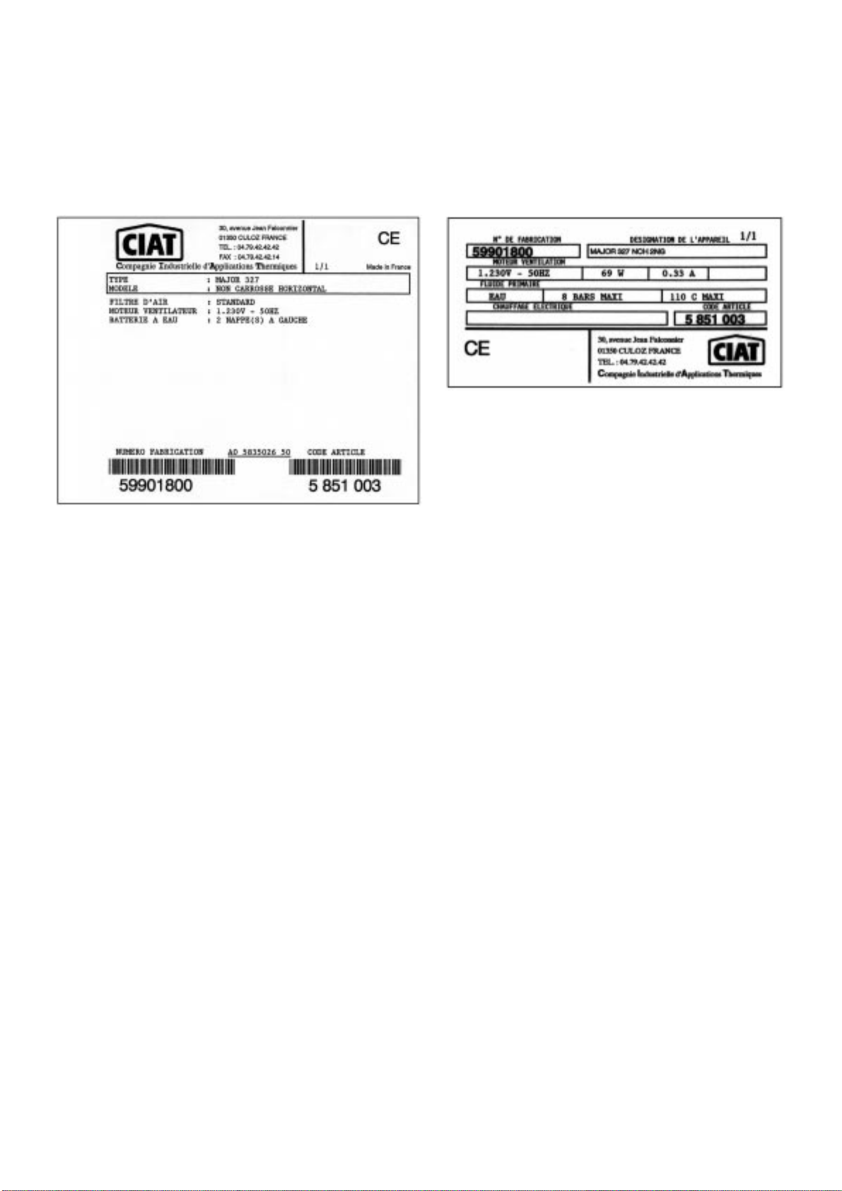
Chaqueappareil possède une plaque signaléti-
que (fig. 4) portant un code article à rappeler
dans toute correspondance.
Unit reception
The unit is supplied in labelled cardboard pack-
aging (fig. 3) with all the unit’s characteristics
(type, model, item code, acknowledgement of
receipt number and customer details, etc.)
enablingyou to identify it precisely.
Each unit has an identification plate (fig.4)
marked with an identification number to be
given in all correspondence.
Entgegennahme des Geräts
Das Gerät wird in einer etikettierten (fAbb. 3) Karton
verpackung mit allen Angaben (Typ, Modell, Artikel
Kode, BestellungsNummer und den Kundenadressen,
...) geliefert. Diese Angaben erlauben Ihnen, das Gerät
genau zu identifizieren.
Jedes Gerät besitzt ein Typenschild (Abb.4) mit Identi
fikationsNummer , die bei jeder Korrespondenz angege
ben werden muss.
Fig. 3
Fig. 4
A la réception des colis, le contrôle de l’état de la
marchandiseà l’arrivée est de la responsabilité
totaledu destinataire :
Pour les manquants, le client doit mentionner
le nombre exact de colis reçus.
En cas d’avaries sur les appareils, le client
doitdécrire impérativement sur le récépissé les
dommages constatés en présence du livreur, et
signer le récépissé qu’après.
IMPORTANT : Ces remarques, conformément
à l’article 105 du Code du Commerce, doivent
être confirmées, par lettre recommandée,
auprésdu transporteur, dans un délai de 3 jours
ouvrables. Les mentions ”sous réserves” et
”sous réserves de déballage” n’ont aucune
valeur. Le client doit déballer la marchandise en
présence du livreur. Des réserves précises à la
livraisonsont nécessaires.
Manutention
Attention : l’appareil doit être manutentionné
avec soins. Les chocs risquent de fausser le
châssis et de détériorer le groupe moto-ventila-
teurs.
Instruction pour démon
tage carrosserie modèle
CV ou CH
Pendantles travaux d’installation de l’appareil,
la carrosserie sera enlevée (en retirant les deux
vis repère 1) et replacée dans son emballage
d’origine.
La pellicule de protection de la peinture devra
être retirée impérativement avant la re-mise en
place définitive de la carrosserie.
When the packages are received, the inspec-
tion of the condition of the goods at arrival is the
recipient’s entire responsibility :
For shortages, the customer must mention the
exact number of packages received.
In the event of defects on the units, the cus-
tomer must describe the damage observed on
the receipt in the presence of the delivery per-
son, and only sign the receipt after having done
this.
IMPORTANT : These remarks, in compliance
with article 105 of the French trade code, must
be confirmed by registered letter to the transport
operatorwithin 3 working days. The terms ”res-
ervations” and ”subject to unpacking” are not
valid. The customer must unpack the goods in
the presence of the delivery person. Specific
reservationsat delivery are required.
Handling
Attention: the unit must be handled with care.
With shocks, there is a danger of buckling the
frame and damaging the fan/motor(s)
assembly.
Instructions for
dismounting the cabinet
model CV or CH
Duringinstallation of the unit, the cabinet will be
lifted (by removing the 2 screws ref.1) and kept
in its original container.
The paint protective film must be peeled off be-
fore final positioning of the cabinet.
Bei Entgegennahme der Pakete: Die Kontrolle des Mate
rialzustands bei seiner Ankunft liegt in der vollständigen
Verantwortlichkeit des Empfängers :
Für fehlendes Material, muss der Kunde die genaue
Anzahl der erhaltenen Pakete anführen.
Im Fall von Transportschäden der Geräte, muss der
Kunde unbedingt, in Gegenwart vom Lieferanten, die
festgestellten Schäden auf der Empfangsbescheinigung
beschreiben und erst anschliessend die Empfangsbe
scheinigung unterschreiben.
WICHTIG :Diese Bemerkungen, gemäss Artikel 105 des
"Code du Commerce", müssen durch ein Einschreiben
an den Spediteur innerhalb von 3 Werkstagen bestätigt
werden. Die Vermerke "unter Vorbehalt" und "unter Vor
behalt von Auspacken" haben keine Gültigkeit. Der
Kunde muss die Ware in Gegenwart vom Lieferanten
auspacken. Bei der Lieferung sind genaue Vorbehalte
notwendig.
Handhabung
Achtung :Das Gerät muss sorgfältig behandelt werden.
Durch Schlageinwirkung kann das Gehäuse beschädigt
und die MotorVentilatoreneinheit zerstört werden.
Anweisung für die Demontage des
Gehäuses des Modells CV oder CH
Während der Installationsarbeiten des Gerätes wird das
Gehäuse abgenommen (durch Zurückziehen der zwei
Schrauben, Markierung 1) und in seiner Originalverpac
kung gelegt.
Die Farbschutzfolie muss unbedingt abgezogen wer
den, bevor das Gehäuse wieder an seinen endgültigen
Platz gebracht wird.

7
Fig. 5
Pour la mise en place définitive, la carrosserie
sera fixée par les deux vis, repère 1.
Nota :
Dans le cas du montage de pieds support ou
boîtede reprise d’air sur modèle CV, CH, enle-
ver les deux pièces repère 2.
Montage 1 D (reprise d’air devant)
ou montage 41 D (reprise d’air dessous)
(voir photo page 16)
Pour enlever la carrosserie, il est nécessaire de
retirer d’abord la grille d’aspiration et le filtre
maintenuspar deux vis, repère 1 (1 de chaque
côté).
Retirer ensuite les 2 autres vis placées à l’inté-
rieur du trou de montage ”filtre et grille” rep. 2.
Enleveralors la carrosserie, replacer le filtre et
la grille avant de remettre cet ensemble dans
l’emballagependant les travaux.
Accessoires
Tous sont livrés dans leurs propres emballages.
Sur chacun d’eux est collé une étiquette définis-
sant le modèle ainsi que le type d’appareil sur
lequelil se raccorde.
For final positioning, the cabinet is to be fixed
with the two screws, ref. 1.
Note :
For mounting support feet or air intake box on
modelsCV, CH, remove the two parts ref. 2.
Assembly 1 D (front air intake)
Assembly 41 D (bottom air intake)
(see photo page 16)
To take off the cabinet, it is first necessary to
withdraw the suction grille and the filter which
are maintained by 2 screws ref. 1 (one on each
side).
Then,take off the 2 other screws remaining in
the hole in which are installed the grille and filter,
ref. 2. Then, withdraw the casing and refit the fil-
ter and the grille before packing the complete
unit during the site works.
Accessories
They are delivered in their own packaging.
There is an information sticker on
packagewhichspecifies the model and type of
unit to which it connects.
Für das endgültige Anbringen des Gehäuses wird dieses
mit den zwei Schrauben befestigt, Markierung 1.
Hinweis:
Für die Montage der Stützfüße oder des Rückluftkastens
bei Modell CV und CH, die zwei Teile, Markierung 2,
entfernen.
Montage 1 D (Rückluft vorn)
oder Montage 41 D (Rückluft unten)
(siehe Foto Seite 16)
Um das Gehäuse zu entfernen ist es notwendig, zuerst
das Ansauggitter und den Filter zu entfernen, welche mit
zwei Schrauben gehalten werden, Markierung 1 (jeweils
1 pro Seite).
Danach die 2 anderen Schrauben, die sich im Inneren
des Montagelochs " Filter und Gitterrost ", Markierung 2,
befinden herausziehen. Danach das Gehäuse
abnehmen, den Filter und Gitterrost wieder einsetzen,
bevor diese Einheit während der Arbeiten wieder in die
Verpackung eingelegt wird.
Zubehörteile
Alle Zubehörteile werden in ihrer eigenen Verpackung
geliefert. Auf jedem Teil ist ein Etikett aufgeklebt, auf dem
das Modell sowie der Gerätetyp angegeben wird, an den
das Teil angeschlossen wird.
Montage pied support CV
ou boîte de reprise d'air CV
CV support feet or CV air intake
box assembly
Montage des Stützfußes CV
oder Rückluftkastens CV
Montage socle NCV
ou boîte de reprise d'air NCV
NCV base or NCV air
intake box assembly
Montage Sockel NCV
oder Rückluftkasten NCV
Fixation B : vis à tôle ø 5,53 x 15,9
Fixing B : metalwork screw ø 5,53 x 15,9
Befestigung B : Blechschraube ø 5,53 x 15,9
Fixing A : metalwork screw ø 3,94 x 9,5
Fixation A : vis à tôle ø 3,94 x 9,5
Befestigung A : Blechschraube ø 3,94 x 9,5
Fig. 6

8
Montage boite de reprise d’air
1) La tôle d’obturation est à fixer à l’arrière de la
boîte ou dessous (suivant montage désiré).
2) Pour les appareils ayant les raccordements
hydrauliquesà droite, le système de commande
du volet est à passer côté tubulures par vos
soins.
Air intake box assembly
1) The blanking sheet is for fixing to the rear or
bottom of the box (depending upon desired as-
sembly).
2) For units with hydraulic connections on the
right,the damper control system is to be passed
on the tube side by your installer.
Montage des Rückluftkastens
1) Das Abschlußblech ist an der Rückseite des Kastens
oder unterhalb des Kastens befestigt (gem. gewünschter
Montage).
2) Bei den Geräten, die rechts mit Hydraulikanschlüssen
versehen sind, muss das Steuersystem der Klappe bau
seits an der Anschußstutzenseite vorbeigeführt werden.
Fig. 7
Mise en place du manchon
télescopique
3) L’étanchéité entre l’appareil et le manchon
télescopiqueest à réaliser par vos soins à l’aide
d’un mastic ou d’un joint mousse
Positioning of the telescopic
sleeve
3) Sealing between the unit and the telescopic
connector is to be done by your installer using
mastic or a foam gasket.
Installation des
TeleskopAnschlusstutzens
3) Die Dichtheit zwischen dem Gerät und dem Teleskop
Anschlusstutzen ist bauseits mittels Mastix oder
Schaumstoffdichtung zu gewährleisten.
Fig. 8
Etanchéité (3)
Seal (3)
Dichtheit (3)
Légère pente vers l’extérieur
Slight slope to the exterior
Geringe Neigung nach aussen

9
Montage diffuseur
Emboiterle pli arrière du diffuseur sur l’appareil
et le maintenir en place au moyen des clips re-
père 4 (un sur chaque face latérale).
Diffuser assembly
Interlock the diffuser rear fold onto the unit and
hold it in place with clips ref. 4 (one on each
side).
Montage des Diffusors
Die hintere Falz des Diffusors in das Gerät einschieben
und mit Klipps in Position halten, Markierung 4 (jeweils 1
an der Seitenfläche).
Fig. 9
Mise en place
de l'appareil
Modèle vertical
– Fixé au mur (par 4 vis),
– Posé au sol avec les pieds supports ou boîte
de reprise d’air.
Modèle horizontal
– Fixé au plafond (par 4 tiges scellées).
Attention :
– Tous les appareils doivent être parfaitement
de niveau.
– Respecter une distance de 110 mm minimum
entre la reprise d’air de l’appareil et le sol
(modèlevertical, montage sans pied) oule mur
(modèle horizontal, montage sans boîte de
reprise d’air).
Positioning
of the unit
Vertical model
– Wall mounted (by 4 screws),
– Resting on the floor with support feet or air in-
take box.
Horizontal model
– Ceiling mounted (by 4 anchor bolts).
Attention :
– All units must be perfectly level.
– Respect a minimum distance of 110 mm be-
tween the unit air intake and the floor (vertical
modelwithout feet) or the wall (horizontal model
withoutair intake box).
Installation
des Geräts
VertikalModell
- An der Wand befestigen (mit 4 Schrauben),
- Mit den Stützfüssen oder dem Rückluftkasten auf den
Boden stellen.
HorizontalModell
- An der Decke befestigen (mit 4 Steinschrauben).
Achtung :
- Alle Geräte müssen absolut waagerecht ausgerichtet
sein.
- Eine Entfernung von mindestens 110 mm ist zwischen
der Rückluft des Gerätes und dem Boden (Vertikal
Modell, Montage ohne Füße) bzw. der Mauer einzuhal
ten (HorizontalModell, Montage ohne Rückluftkasten).

10
Raccordement
hydraulique
Les batteries sont équipées de raccords
avec purgeur d’air repère 1 et vidange repère
2.Un simple tournevis plat suffit pour dévisser
ces purges.
Les raccordements hydrauliques sont pré-
vus à gauche ou à droite de l’appareil, en regar-
dant face au soufflage. Entrée en bas, sortie en
haut.
Pour les appareils comportant des vannes
de régulation, se conformer aux indications por-
tées sur l’appareil.
Lors du montage de robinets ou autres maté-
riels, il est impératif de maintenir les raccords à
l’aide d’une clé (fig.10), afin d’éviter la torsion
des tubulures.
Bac auxiliaire des condensats pour modèle
vertical CV, NCV (option).
Hydraulic connections
The coils are equipped with connections hav-
ing air relief valves (item 1) and drains (item 2).
Unscrew these drain caps using a standard
flat-tippedscrewdriver.
The hydraulic connections are on the left or
the right when looking at the discharge side.
Bottominlet, top outlet.
For units fitted with control valves, follow the
indicationsmentioned on the unit.
When installing cocks or other fittings, the
connectionmust be held by a wrench (fig.10) so
as to avoid distortion of the tubes.
Auxiliarycondensate pan for CV, NCV verti-
cal model (optional).
Wasseranschlüsse
Die Register sind mit Anschlüssen mit Entlüftungs
ventil Markierung 1 und Ablaß Markierung 2 verse
hen.Ein einfacher Flachschraubenzieher reicht aus, um
diese Entlüftungsventile loszuschrauben.
Die Wasseranschlüsse befinden sich an der linken
oder der rechten Seite des Geräts. Eintritt unten, Austritt
oben.
Bei den Geräten, die mit Regelventilen ausgestattet
sind, müssen die Angaben beachtet werden, die auf dem
Gerät stehen.
Bei der Montage von Sperrhähnen oder anderen
Materialien ist es unbedingt erforderlich, die Anschlüsse
mit Hilfe eines Schlüssels (Abb. 10) festzuhalten, um
eine Verdrehung der Anschlußstutzen zu vermeiden.
ZusatzKondensatwanne für VertikalModell CV, NCV
(Option).
Fig. 10
1
2
Dans le cas d’appareil équipé de deux batte-
ries (”Système 4 tubes”), dans le sens de l’air, la
batteriechaude se situe avant la batterie froide
(sauf spécifications contraires) (fig.11).
In units with two coils (”4 pipe system”) the
heating coil is located before the cooling coil in
the sense of the air flow (except for contrary
specifications)(fig.11 ).
Wenn ein Gerät mit zwei Registern (" 4LeiterSys
tem") ausgestattet ist, befindet sich in Luftrichtung das
Warmregister vor dem Kaltregister (wenn nichts anderes
angegeben ist) (abb. 11).
Fig. 11
Afin d’éviter tout risque de condensation en
fonctionnement avec de l’eau glacée, il est
nécessaire de calorifuger les tuyauteries sur
toutes leur longueur en s’assurant que l’étan-
chéité soit parfaite aux extrémités.
L’eaucondensée est évacuée par une durite
plastiqueø 15/19 dans les appareils verticaux
et par un tube cuivre ø 16 ext. dans les appareils
horizontaux.
La canalisation d’évacuation peut-être indé-
pendante pour chaque appareil ou raccordée à
une tuyauterie principale d’évacuation.Utiliser
un tube d’évacuation de ø 16 mm transparent,
ayant une pente de 2 cm/m minimum, avec un
déniveléconstant tout le long du parcours. Pré-
voir un siphon d’au moins 5 cm pour éviter tout
refoulement de gaz ou d’odeurs désagréables.
To avoid all risks of condensation when oper-
atingwith chilled water, the full length of tubes
must be insulated and the ends perfectly
sealed.
Condensateis drained by a ø 15/19 plastic
tube in vertical units and a ø 16 copper tube in
horizontal units.
The drainage pipework can be separate for
each unit or connected to a main drain.
Use a 16 mm diameter transparent evacuation
tube, with a minimum slope of 2 cm/m, with a
constant difference in level along its path.
Providea siphon of at least 5 cm to prevent any
dischargeof gas or unpleasant odours.
Um jegliche Kondensatbildung bei Betrieb mit Kalt
wasser zu vermeiden, ist es erforderlich, die Rohrleitun
gen in ihrer gesamten Länge mit Wärmedämmung zu
versehen, wobei sicherzustellen ist, dass die Dichtheit
an den Endstücken gewährleistet ist.
Das kondensierte Wasser wird von einem Plastikdurit
ø 15/19 in den VertikalGeräten und über ein Kupferrohr ø
16 bei den horizontalen Geräten abgeleitet.
Das Ablassystem kann für jedes Gerät separat oder
an eine Hauptrohrleitung angeschlossen sein.
Benutzen Sie einen durchsichtigen Ablasschlauch von ø
16mm mit einem minimalen Gefälle von 2cm/m und
einem konstantem Gefälle auf dem gesamten Weg.
Sehen Sie einen Syphon von 5 cm vor, um jeden Gas
Rücklauf oder schlechte Gerüche zu vermeiden.

11
Raccordements
électriques
Avant de raccorder l’appareil au réseau, s’assu-
rer que la tension est bien celle indiquée sur la
plaque signalétique de l’appareil.
Le raccordement au réseau devra être
conforme aux règles d’installation en vigueur.
La mise à la terre de l’appareil est impérative.
Notreresponsabilité ne saurait être engagée en
cas d’accidents consécutifs à une mise à la
terre incorrecte ou inexistante.
Pour les appareils comportant des équipe-
ments électriques optionnels, se conformer au
schéma électrique joint avec l’appareil.
Pour des applications client, le schéma électri-
ques et à concevoir à partir des schémas géné-
riques fournis ci-dessous.
Attention :
Les fils NOIR, BLEU et ROUGE ne doivent
jamaisêtre reliés entre eux.
Câblage interne de l’appareil stan-
dard ramené sur bornier en confi-
guration 2 tubes ou 4 tubes :
Chaqueventilo convecteur doit être commandé
par son propre boîtier de commande. La com-
mandede plusieurs ventilo-convecteurs à partir
d’un même boîtier est déconseillé et nécessite
l’emploi de relais (consulter nos services tech-
niques).
Modèle vertical CV, NCV
Electrical
connections
Beforeconnecting the unit to the mains, make
sure that the voltage is the same as that indi-
cated on the unit identification plate.
The connections to the mains should comply
with the applicable installation regulations. The
unit must be earthed. We cannot be held
responsiblefor accidents following incorrect or
non-existent earthing.
With appliances featuring optional electronic
components,comply with the electrical diagram
suppliedwith the appliance.
For customer applications, the electrical dia-
gram is to be drawn up from the generic dia-
grams provided below.
Caution:
The BLACK, BLUE and RED wirds must never
be interconnected.
Internal wiring of standard unit on
terminal strip for 2-pipe or 4-pipe
configuration :
Each fan coil unit is governed by its own control
box.
Control of several fan coil units from the same
box is not recommended and requires the use of
relays (consult our technical department)
.
Vertical model CV, NCV
Elektrische
Anschlüsse
Bevor das Gerät an das Netz angeschlossen wird, versi
chern Sie sich, dass die Spannung diejenige ist, die auf
dem Typenschild angegeben ist.
Der Netzanschluss muss den geltenden Installationsre
gelungen konform sein. Die Erdung des Geräts ist unbe
dingt notwendig. Wir übernehmen keine Haftung für
Unfälle, die nach einer unvorschriftsmässigen oder nicht
betehenden Erdung passieren.
Bei Geräten, die mit optionalen elektrischen
Ausrüstungen versehen sind, ist das ElektroSchema zu
beachten, welches mit dem Gerät geliefert wird.
Für die Anforderungen des Kunden ist das
ElektroSchema anhand des Schemas zu erstellen, wel
ches nachstehend aufgeführt wird.
Achtung :
Die schwarzen, blauen und roten Drähte dürfen niemals
miteinander verbunden werden.
Interne Verdrahtung des StandardGeräts
( auf Klemmleiste mit Konfiguration 2Lei
terSystem oder 4LeiterSystem) :
Jeder Klimakonvektor muss über seine eigene Steue
reinheit gesteuert werden. Es wird nicht empfohlen, meh
rere Klimakonvektoren über eine Steuereinheit zu
steuern, da hierfür Relais verwendet werden müssen
(wenden Sie sich an unseren technischen Kunden
dienst).
Vertikale Ausführung CV, NCV
Fig. 12
Commutateur
Switch
Schalter
Condensateur
Capacitor
Kondensator
Alimentation
Supply
Stromversorgung
Câble d’alimentation
Supply cable
Einspeisungskabel
NULL
Ventilator-Motor
* Protecteur thermique à réenclenchement
automatiqueincorporé au moteur.
P.V. = Petite vitesse
M.V. = Moyenne vitesse
G.V. = Grande vitesse
* Auto-reset overheat protector integrated in
the motor.
P.V. = Low speed
M.V. = Medium speed
G.V. = High speed
* Automatischer WiedereinschaltThermoschutz ist im
Motor eingebaut.
P.V. = Geringe Geschwindigkeit
M.V. = Mittlere Geschwindigkeit
G.V. = Hohe Geschwindigkeit

12
Modèle horizontal CH, NCH
Horizontal model CH, NC
Horizontale Ausführung CH, NCH
Fig. 13
Câblage interne de l’appareil stan-
dard ramené sur bornier en confi-
guration 2 tubes + Electrique
(avec 1 ou 2 résistances) :
Modèle vertical CV, NCV
0 / 4,6 kW
Internal wiring of standard unit on
terminal strip for 2-pipe +
Electrical heater configuration
(with 1 or 2 elements) :
Vertical model CV, NCV
0 / 4,6 kW
Interne Verdrahtung des StandardGeräts
auf Klemmleiste mit Konfiguration
2LeiterSystem + EHeizung (mit 1 oder 2
Widerständen) :
Vertikale Ausführung CV, NCV
0 / 4,6 kW
Fig. 14
Drehzahlschalter
CIAT préconise l’utilisation d’une régulation de
l’appareil sur l’eau (active sur la ou les vannes
(s)) et la batterie électrique.
Instructions générales relatives à la sécurité.
CIAT recommends using a governor for the
appliance when on the water (acting on the
valve(s) and the electric coil).
General safety instructions.
CIAT empfiehlt die Verwendung einer Regelung des
Geräts über das Wasser (aktiv über das/die Ventil(e) und
das EHeizregister.
Allgemeine Instruktionen bezüglich der Slcherheit..

13
Asservissement au ventilateur
La batterie électrique (1 ou 2 résistances)doit
être obligatoirement asservie au ventilateur.
Tout arrêt volontaire ou intempestif du groupe
de ventilation doit entraîner impérativement la
coupurede l’alimentation des résistances élec-
triques.
Modèle horizontal CH, NCH
0 / 2,8 kW
Fan control
The electric heater must be controlled by the
fan. Any voluntary or untimely stoppage of the
ventilationunit must cause the power supply to
the electric resistances to be cut off.
Horizontal model CH, NCH
0 / 2,8 kW
Ventilatorsteuerung
Das EHeizregister (1 oder 2 Widerstände) muss obliga
torisch an den Ventilator angesteuert sein. Jeder absicht
liche oder unpassender Stillstand der Ventilatorgruppe
muss unbedingt eine Unterbrechung der
WiderstandsStromversorgung mit sich bringen.
Horizontale Ausführung CH, NCH
0 / 2,8 kW
Fig. 15
Modèle horizontal CH, NCH
3 / 4,6 kW
Horizontal model CH, NCH
3 / 4,6 kW
Horizontale Ausführung CH, NCH
3 / 4,6 kW
Fig. 16

14
Protection contre la surchauffe
La batterie comporte un thermostat de sécurité
à réarmement manuel (repère B). Celui-ci est
accessible après démontage de la carrosserie.
Avant de réarmer cette sécurité, chercher les
causes de la surchauffe.
De nombreuses causes peuvent entraîner une
surchauffe générale des éléments électriques
et par la même déclencher le thermostat de
sécurité :
mise sous tension de la batterie sans ventila-
tion,
colmatage partiel du filtre,
régulation arrêtant simultanément la batterie
et le ventilateur.
Protection against overheating
The coil is equipped with a manual reset safety
thermostat (item B). This thermostat can be
accessed after disassembling the body. Before
resettingthe safety device, locate the causes of
the overheating.
Many causes can induce general overheating
of the electric elements and thus trigger the
safety thermostat :
coil switched on without ventilation,
partial clogging of filter,
control system stopping the coil and the fan
simultaneously.
Schutz gegen Überhitzung
Das Register enthält ein Sicherheitsthermostat mit
manuellem Reset (Markierung B). Dieses ist nach Aus
bau des Gehäuses erreichbar. Bevor Sie diese Sicher
heit wiedereinschalten, suchen Sie die Gründe der
Überhitzung.
Mehrere Gründe können eine allgemeine Überhitzung
der elektrischen Elemente mit sich bringen und dadurch
das Sicherheitsthermostat auslösen :
Unter Spannung Stellung des Registers ohne Lüf
tung,
teilweise Verschmutzung des Filters,
Regelung, die das Register und den Ventilator gleich
zeitig abschaltet.
Fig. 17 Fig. 18
Régulation
de la batterie électrique
Appareil tout électrique
Le thermostat d’ambiance 1 ou 2 étages doit
agir uniquement sur la batterie électrique mais
en aucun cas sur le ventilateur.
La ventilation doit être permanente.
Dans le cas d’une coupure simultanée, il estab-
solument indispensable de prévoir une tempori-
sationne permettant l’arrêt du ventilateur qu’a-
près coupure de la batterie. Il est nécessaire de
dissiper la chaleur accumulée dans les élé-
ments chauffants pendant un temps variable,
selon la puissance de la batterie.
Se conformer au schéma électrique joint avec
l’appareil.
Adjustment
of the electric heater
All electric unit
The 1 or 2 stage ambient thermostat must only
controlthe electric heater and never the ventila-
tion fan.
Ventilation must be permanent.
In the case of a simultaneous cut, it is absolutely
indispensableto have a delay that will not allow
the fan to stop until after the heater. It is neces-
sarytodissipatetheheataccumulatedin the
elements for a variable period, depending
upon the heater battery power.
Follow the wiring diagram attached to the unit.
Regelung
des EHeizregisters
Vollständig elektrisches Gerät
Das Raumthermostat, 1 oder 2 Stufen, darf nur auf das
elektrische Register einwirken und in keinem Fall auf den
Ventilator.
Die Ventilation muss permanent sein.
Bei SimultanAbschaltung ist es unbedingt erforderlich,
eine Zeitschaltung vorzusehen, die den Halt des Ventila
tors erst nach Abschalten des Registers erlaubt. Es ist
notwendig, die angesammelte Wärme in den Heizele
menten während eines variablen Zeitraums abzuführen,
gemäss der Leistung des Registers.
Das dem Gerät beigefügte ElektroSchema ist zu beach
ten.

15
Entretien
Avant toute dépose de la carrosserie et
interventionà l’intérieur de l’appareil, met-
tre l’appareil hors-tension en coupant l’ali-
mentationélectrique.
Modification du câblage
électrique
L’unitéterminale dispose d’un moteur à 7 vites-
ses dont 3 sont pré-cablées en usine. Pour
modifierce câblage usine, il vous suffit à l’aide
d’unpetit tournevis à portée plate de retirer le fil
d’alimentation, aprés la mise hors tension
(fig.18/19). Puis de sélectionner le repére
moteurdésiré et de clipser simplement à la main
ce fil d’alimentation (fig.20) sans l’aide du tour-
nevis.
Servicing
Before removing the body and performing
any intervention inside the unit, switch off
unit by switching off the electricity supply.
Modification of electrical
wiring
The terminal unit is equipped with 7-speed
motor, for which 3 speeds are pre-wired in the
factory. To modify the factory wiring, simply
removethe power supply wire using a small flat
screwdriver, after switching off the unit (fig.
18/19). Then select the required motor mark
and simply clip on the power supply wire by
hand (fig. 20) without using the screwdriver.
Wartung
Vor jedem Abbau des Gehäuses und Eingriff inner
halb des Geräts, schalten Sie die Spannung des
Geräts ab, indem Sie die Stromversorgung unterbre
chen.
Modifizierung der elektrischen
Verdrahtung
Der Klimakonvektor verfügt über einen 7stufigen Motor,
von denen 3 werkseitig vorverkabelt sind. Um diese
werkseitige Verkabelung zu modifizieren, reicht es aus,
das Einspeisungskabel des Motors mit Hilfe eines
Schraubenzieher rauszuziehen, nachdem die Spannung
abgeschaltet wurde (Abb.18/19). Danach wählen Sie die
gewünschten Motorstufen und klipsen Sie das Einspei
sungskabel mit der Hand (Abb.20) einfach wieder an.
Fig. 19
Fig. 20 Fig. 21
Filtre d’air
Le filtre est indispensable pour le bon fonction-
nement de l’appareil sous peine de colmatage.
Le filtre doit être nettoyé périodiquement par
aspiration,dans le sens inverse du passage de
l’air.
Examinerrégulièrement l’aspect du filtre afin de
définirla périodicité du nettoyage, qui varie sui-
vant la nature des locaux et les conditions d’utili-
sation.
Sur demande nous pouvons fournir des filtres.
de rechange.
Air filter
The filter is essential for the correct operation of
the unit and is subject to clogging.
The filter must be periodically cleaned by vacu-
umingin the opposite sense to the air flow.
Examinethe appearance of the filter regularly to
definethe frequency of cleaning, which varies
accordingto the type of premises and the condi-
tions of use.
We can supply spare filters, on request.
Luftfilter
Der Filter ist für das ordnungsgemäße Funktionieren des
Gerätes unbedingt erforderlich und darf nicht verstopft
sein.
Der Filter ist in regelmäßigen Abständen durch
Absaugen zu reinigen, und zwar in umgekehrter
Richtung des Luftstroms.
Das Aussehen des Filters regelmäßig kontrollieren, um
so die Zeitabstände für die Reinigung festzulegen, die
abhängig von der Beschaffenheit der Räume und den
Installationsbedingungen sehr unterschiedlich sein
können.
Auf Anfrage können wir Austauschfilter liefern.

16
Retrait du filtre d’air
Pour retirer le filtre suivre l’ordre et le sens des
flèches.
Air filter removal
Follow the order and direction of arrows to re
move the filter.
Herausnehmen des Luftfilters
Um den Filter herauszunehmen, die Reihenfolge und die
Richtung der Pfeile beachten.
Fig. 22
Sur les appareils équipés d’une grille à l’aspira-
tion, faire pivoter celle-ci dans le sens de la flè-
che (rep. a) et suivre ensuite le même proces-
sus indiqué ci-dessus.
On units fitted with an intake grille, turn it round
in the direction of the arrow (ref. a) and follow
then the procedure indicated above.
Bei den Geräten, die mit einem Ansauggitter versehen
sind, dieses in Richtung des Pfeils drehen (Markierung a)
und danach das nachstehende Verfahren befolgen.
Fig. 23
Montage 1 D (reprise d’air devant)
ou montage 41 D (reprise d’air dessous)
Enlever la grille d’aspiration maintenue par 2
vis, repère 1 (1 de chaque côté) et retirer le filtre.
Assembly1 d (front air intake)
or assembly 41 d (bottom air intake)
Take off the suction grille maintained by 2
screws, ref. 1 (one on each side) and withdraw
the filter.
Montage 1 D (Rückluft vorn)
oder Montage 41 D (Rückluft unten)
Das Ansauggitter, welches mit 2 Schrauben gehalten
wird, Markierung 1 (1 an jeder Seite) entfernen und den
Filter herausziehen.
Démontage de la carrosserie
Remouving of the cabinet
Ausbau des Gehäuses
Fig. 24 Fig. 25
Fig. 26

17
Groupe
moto-ventilateur(s)
De temps en temps vérifier l’état de propreté
des turbines et du moteur ; si nécessaire, les
nettoyerà l’aide d’un aspirateur en prenant soin
de ne pas les endommager.
Le moteur électrique est à paliers autolubrifiants
graissés pour la vie du moteur.
Batterie d’échange
L’état de propreté de la batterie est un facteur
déterminantpour le bon rendement de l’appa-
reil. Le nettoyage de la batterie peut se faire à
l’aided’un aspirateur.
Bac de récupération des conden-
sats
Vérifier périodiquement que l’orifice d’évacuation
des condensats ne soit pas obstrué.
Carrosserie
Passer une éponge humide légèrement savon-
neuse sur les parois et faire briller à l’aide d’un
chiffon doux et sec.
Ne jamais utiliser de produits abrasifs.
Essais et garantie
Tous nos appareils sont essayés et éprouvés
avant expédition.
Ils sont garantis contre tous vices de fabrica-
tion, mais notre responsabilité ne saurait être
engagéeen cas de corrosion quelconque. Les
moteursne sont pas garantis en cas d’erreur de
branchementélectrique, d’une mauvaise pro-
tectionou d’une utilisation sans filtre d’air.
Notre garantie couvre les moteurs dans le
cas de la garantie de notre fournisseur. A aucun
moment, l’installateur ne doit intervenir sur le
moteur. Dans le cas contraire, il perdrait le bé-
néfice de la garantie éventuelle.
Fan-motor(s) assembly
From time to time check cleanliness of the fan
and motor ; if necessary clean with a vacuum
cleanertaking care not to cause damage.
The electric motor bearing are life lubricated.
Exchanger coil
The clean state of the coil is a positive factor for
proper output of the unit. The coil can be
cleanedwith a vacuum cleaner.
Condensate drain pan
Periodically check that the condensate drain
openingsare not blocked.
Cabinet
Clean with a lightly soaped sponge and shine
with a soft dry cloth.
Never use an abrasive product.
Test and guarantee
All of our units are tested and approved before
shipping.
The guarantee covers manufacturing faults ;
but we cannot be held responsible for corrosion
damage.
Motors are not guaranteed against faulty con-
necting,poor protection or use without an air fil-
ter.
Our guarantee coincides with that of the
motorsupplier. The installer should never tam-
per with the motor. If this occurs, any possible
guarantee benefits are lost.
MotorVenitlatorgruppe(n)
Die Laufräder und den Motor von Zeit zu Zeit auf Sauber
keit prüfen, mit einem Staubsauger reinigen, dabei
darauf achten, die Teile nicht zu beschädigen.
Der Elektromotor ist mit selbstschmierenden Lagern ver
sehen, die für die Lebensdauer des Motors dauerge
schmiert sind.
Ersatzregister
Die Sauberkeit des Registers ist ein wichtiger Faktor für
die korrekte Leistung des Gerätes. Das Register kann
mit Hilfe eines Staubsaugers gereinigt werden.
Kondensatwanne
Regelmäßig prüfen, dass die Ablaßöffnung für das Konden
sat nicht verstopft ist.
Gehäuse
Mit einem leicht seifenhaltigen feuchten Schwamm die
Wände abwischen und mit einemweichen und trockenen
Tuch nachreiben. Niemals Schleifmittel verwenden.
Tests und Garantie
Alle unsere Geräte werden vor dem Versand getestet
und geprüft.
Die Garantie erstreckt sich auf alle Herstel
lungsmängel, jedoch haften wir nicht bei Korrosion
irgendwelcher Art. Bei fehlerhaftem elektrischen Ans
chluss der Motoren, unzulänglichem Schutz oder Betrieb
ohne Luftfilter besteht kein Garantieanspruch.
Unsere Motorengarantie gilt, sofern die Garantie sei
tens unseres Lieferanten gilt. Der Monteur darf auf kei
nen Fall irgendwelche Eingriffe am Motor vornehmen.
Bei Zuwiderhandlung wäre der etwaige Garantieans
pruch hinfällig.

18
CIAT est en conformité avec le marquage CE,
autorisantune libre circulation de ses appareils
sur l’ensemble du territoire de l’Union Euro-
péenne.Ce marquage est un gage de sécurité
et de protection des personnes.
CIAT complies with the CE mark, authorising
the free circulation of its units throughout the
European Union. This mark is a guarantee of
personalsafety and protection.
CIAT ist der CE Kennzeichnung konform, die eine freie
Verbreitung seiner Geräte auf der Gesamtheit der Euro
päischen Union erlaubt. Dieses Kennzeichen dient zur
Sicherheit des Anwenders.
This manual suits for next models
3
Table of contents
Other CIAT Fan manuals
Popular Fan manuals by other brands

2VV
2VV ALFA EC Series Full manual

Ruck Ventilatoren
Ruck Ventilatoren DVA EC 30 Series Assembly instruction

Hunter
Hunter Abernathy installation manual

PSM
PSM ELITE HSC E60L user guide

Cumberland
Cumberland Competitor PNEG-1559 Installation and operation manual

VES
VES Ecovent EVH Series Operation & maintenance manual