manuals.online logo
Brands
  1. Home
  2. •
  3. Brands
  4. •
  5. CIAT
  6. •
  7. Portable Generator
  8. •
  9. CIAT GGS A050 Ch 45 Guide

CIAT GGS A050 Ch 45 Guide

This manual suits for next models

34

Popular Portable Generator manuals by other brands

Kohler 20EORZ Operation

Kohler

Kohler 20EORZ Operation

Powerhorse 83171 owner's manual

Powerhorse

Powerhorse 83171 owner's manual

HURST ML-630-SI instruction manual

HURST

HURST ML-630-SI instruction manual

ETQ TG4000 owner's manual

ETQ

ETQ TG4000 owner's manual

Briggs & Stratton 40265 Illustrated parts list

Briggs & Stratton

Briggs & Stratton 40265 Illustrated parts list

evertz 7700 Series manual

evertz

evertz 7700 Series manual

Firefly Cygnus CYG2400/460/24 user manual

Firefly

Firefly Cygnus CYG2400/460/24 user manual

Owon Waveform Generator manual

Owon

Owon Waveform Generator manual

Draper PG950S Instructions for

Draper

Draper PG950S Instructions for

SDMO SH 4000 Generating set user and maintenance manual

SDMO

SDMO SH 4000 Generating set user and maintenance manual

EINHELL STE 5500 operating instructions

EINHELL

EINHELL STE 5500 operating instructions

Wanco WI3000P Operator's manual

Wanco

Wanco WI3000P Operator's manual

Full Boar FBT-3300 instruction manual

Full Boar

Full Boar FBT-3300 instruction manual

Dwyer Instruments ASG manual

Dwyer Instruments

Dwyer Instruments ASG manual

Westinghouse WH1000i Series owner's manual

Westinghouse

Westinghouse WH1000i Series owner's manual

Wallenstein GF5000A manual

Wallenstein

Wallenstein GF5000A manual

Leroy-Somer LSA 49.1 Installation and Maintenance

Leroy-Somer

Leroy-Somer LSA 49.1 Installation and Maintenance

Yamakoyo SH2900DX owner's manual

Yamakoyo

Yamakoyo SH2900DX owner's manual

manuals.online logo
manuals.online logoBrands
  • About & Mission
  • Contact us
  • Privacy Policy
  • Terms and Conditions

Copyright 2025 Manuals.Online. All Rights Reserved.

06- 2011
NA11.45 A
GGS
Installation
Operation
Commissioning
Maintenance
HOT AIR GENERATOR WITH GAS BURNER
1er couv.qxd 10/07/2009 16:14 Page 1


04 - 2011































































































CONTENTS
1. DESCRIPTION OF THE UNIT
2. INSTALLATION & CONNECTION
3. COMMISSIONING
4. CARE AND MAINTENANCE
5. PROBLEMS
6. CE CERTIFICATE OF CONFORMITY
Note to reader: This document is provided for guidance only. Certain modifications may apply. The manufacturer shall not be
held liable for potential errors or omissions in these instructions.


1

1. DESCRIPTION OF THE UNIT

3 CONFIGURATION TYPES:
•Int. burner (fig1.)

•Ext. burner (fig2.)
•Burner fixed outside (fig3.)




Burner cover







































Power and electrical control box (optional)




Flue, gas expansion valve, buffer tank and sectional valves not supplied
Three thermostat chamber outlet
Use a differential pressure switch or
another system to control the air flow
(compulsory). This component is provided
by CIAT service if the power and electrical
control box is supplied.
Chamber cleaning access hatch
Tubular plate heat exchanger and
smoke box
Combustion chamber
- Stainless steel chamber
- Stainless steel exchanger
- Stainless steel smoke box
- Hot air deflector: zinc-plated sheet metal
Threaded condensate
drain union
Integrated
bypass
Flue (not supplied)
Fan always upstream of the
combustion chamber
Burner access doo
r
Burner
Main components:
1 air pressure switch
1 min. and max. gas pressure switch
1 ignition and safety valve block
1 gas filter
1 flame detection and control unit
Burner power supply voltage: single-phase 240
V or three-phase 240/400 V; 50 Hz + Earth
Panel to access chamber
cleaning hatch 3-thermostat
access panel
2

DIMENSIONS
Ø D
G
C1
Fig.1Fig.2
Fi
g
.3
Burnercasing
3

TABLE OF DIMENSIONS
CHAMBER BURNERS
P Max Kw AIR FLOW
4

dP
a c
h
am
b
er
combustion circuit
dP
a c
h
am
b
er a
i
r
side
Ch
am
b
er
weight kg
UNIT
Volume of gas combustion products
m3/ m3
GN 21.05 x (gas flow m3/h)
Propane 59.04 x (gas flow m3/h)
If the air-handling unit is equipped with a fan with a 2-speed or variable-speed motor, the control must
ensure that the reduction in the air flow automatically causes a reduction in power.

PICTOGRAMS




Grounding compulsory
Condensate drain siphon

Air flow Electric heater
2. INSTALLATION & CONNECTION
GAS SUPPLY
For a supply pressure greater than that recommended by the burner manufacturer, a pressure expansion valve must be
installed to obtain the correct value while respecting the flow.
The installation must have a gas supply cutoff valve for each burner and a manual valve located at the entrance to the
premises, as per the conditions set out in article GZ 15 (fire safety regulations for establishments open to the public).
5

Schematic diagram of the gas system
Unit exterior Unit interior (when applicable)
Manual safety valve Expansion valve
(option)
(not supplied by CIAT)
Gas inlet
Operating pressure
Natural gas: MPA = 30 to 400 mbar expansion 18 mbar
MPB = 0.4 to 4 bar expansion 18 mbar/300 mbar
LPG: BUTANE expansion 28 mbar/118 mbar
PROPANE expansion 37 mbar/148 mbar
•Recommendation for calculating the pipework diameter, see following sections.
•The pipework must always be installed with the greatest care. The local gas distribution prescriptions must be strictly
followed (in FRANCE comply with DTU 61.1).
Burnt gas evacuation duct
The duct should preferably be made from special gas-grade aluminium sheet with a purity of at least 99.5% or from stainless
steel sheet metal.
the duct is neither flush-mounted nor engraved but fixed only to the masonry using clamps.
Each duct inlet is labelled to indicate that it can only be used for the evacuation of gas combustion products.
To burner
Flue duct
(not supplied by CIAT)
Buffer tank
(
not su
pp
lied b
y
CIAT
)
1 m maximum
The roof outlet complies with the usual standards.
Minimum height of 0.40m above any ridge (sloping roof).
Minimum height of 1.20m above a terrace roof (15% slope).
A T-joint with an inspection cover is provided at the base.
Double-wall ducts are recommended to prevent the formation of condensates.
The duct cross-section must not be smaller than that of the unit's connection nozzle.
The ducts are positioned at least 20 cm from any flammable material.
The burnt gas ducts are made in accordance with the prescriptions of the CE directives.
Flame length and flue installation principle
int. evacuation Ø1 m min
Condensate draining
Condensate drain Ø3/4"
6

The sum of the pressure drops (flue duct + combustion chamber) must not exceed that authorised by the burner (refer to the
table in the "Dimensions" section).
The combustion gas outlet must extend at least 1 metre above the top of the roof. It is also necessary to check that the
combustion gas cannot be recycled in the premises (allow a sufficient distance between the flue outlet and the building air
inlets).
The condensate drains will be connected to the gutter via a sealed duct.
POWER SUPPLY AND ELECTRICAL CONNECTION
All the electrical connections and wiring are configured and installed in accordance with the codes, local regulations and wiring
diagrams located inside the units.
Check that the available electrical power supply
corresponds to the characteristics on the
manufacturer's
p
late.
Connecting the safety unit
Safety thermostat mounted at the chamber outlet
•1st thermostat (automatic reset)
Adjustable using the knob on the thermostat housing (range from 0 to 80°C).
This stage can control the ventilation units in fresh air only operation (set to approximately 25°C).
•2nd thermostat (automatic reset)
Adjustable inside the unit (range from 30 to 120°C).
This stage provides overheating protection for the combustion chamber (set to approximately 90°C). The stage must be
incorporated into the burner's control chain.
•3rd thermostat (automatic reset)
Adjustable inside the unit (range from 40 to 100°C).
This stage provides overheating protection for the combustion chamber (set to approximately 100°C). The stage must be
incorporated into the burner's control chain.
Honeywell L4064N FAN and LIMIT thermostat
LIMIT-2 thermostat
Type TR2 Code 541302
White button
Automatic
Button raised
LOAD
FAN
Damper
control
Automatic reset
LOAD
FAN
25° LIMIT
100°C
LIMIT
Manual reset
Check that the strap
has been correctly cut
LINE LINE
Red push button
Resetting
FAN
FAN LIMIT LIMIT
LINE
LOAD LINE LOAD
Combustion chamber adjustment
servomotor control (1-wire control)
Temperature < 25°C: damper closed
Temperature > 25°C: damper open
To be inserted in the
burner control duct
7

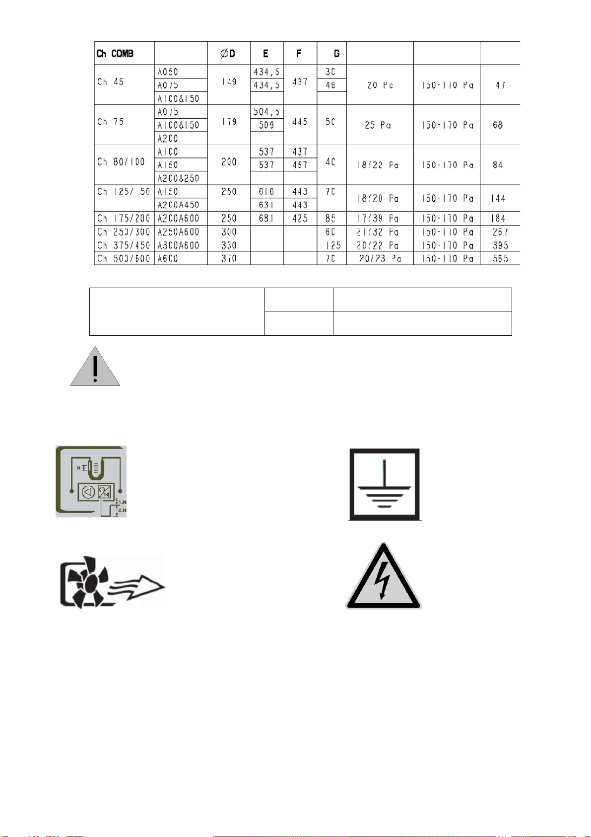
Breaking capacity for each thermostat
- 15 A (2.5 A) at 250 V
- 10 A (2.5 A) at 400 V
•Only qualified personnel may carry out work on the thermostat.
•When replacing an old thermostat with a new model, remember to carry out the wiring
modifications and run an operating test.
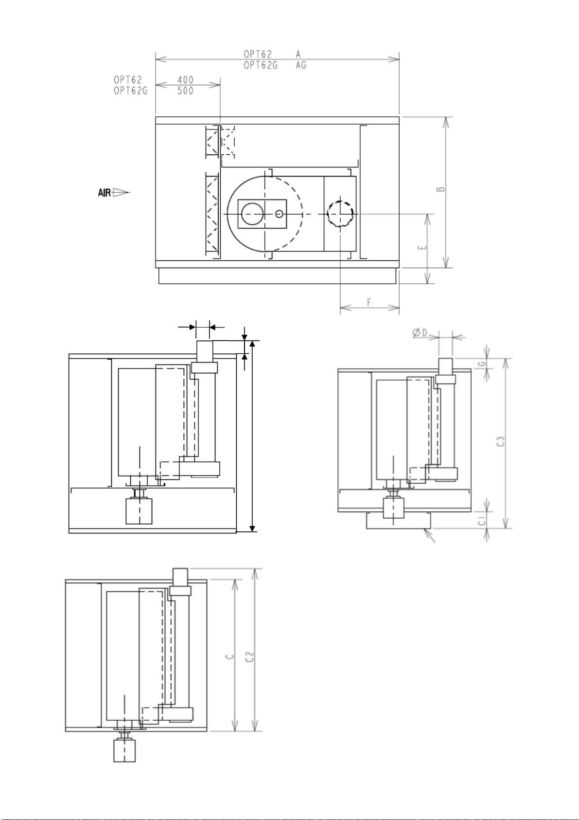
VENTILATION UNITS
1. Fresh air only operation
If the temperature at the chamber outlet is lower than 25°C, the combustion chamber ventilation unit is 90% closed.
If the temperature at the chamber outlet is greater than 25°C, the combustion chamber ventilation unit is open.
The ventilation unit can be controlled by an On/Off servomotor without a zero return (zero return by phase inversion). This
servomotor may be controlled by the thermostat's 1st stage (to fine-tune the air outlet temperature setting, the servomotor may
be the modulating type controlled by a modulating regulator with a supply air sensor).
The servomotor will have a mechanical stop to allow the opening and closing percentages to be set (travel limit).
2. Adjusting the bypass flap
To obtain the ideal temperature at the combustion chamber outlet and reduce the risk of condensation, please set the
combustion chamber bypass according to the exhaust temperature (min. 160°C in the worst-case scenario).
Note: the settings are given for information only; they must be fine-tuned during operation at a low return temperature. A larger
bypass opening improves operation.
GENERATOR
For safety and maintenance reasons, please observe the clearances given below.
Access side
La distance between the GGS generator and the wall must be at least 900 mm (the desired distance is the depth of the GGS
generator).
Opposite side
The distance between the GGS and the wall must be determined on the basis of how the burnt gas duct is installed (see section
relating to its installation).
The unit must be installed in accordance with current regulations and standards in a well-ventilated area.
The unit must not be installed in an area with a risk of fire (fine flammable dust) or explosion, or in an area
containing aggressive products such as trichloroethylene, perchlorate, etc.
The fresh air flow required to supply combustion is at least 2 m3/h per kW of heat flow.
GAS PIPE AND ELECTRICAL ROUTING
Inside the GGS generator
•Observe the correct clearance for the smoke box access panel.
•Allow room to access the minimum gas pressure switch (adjustment).
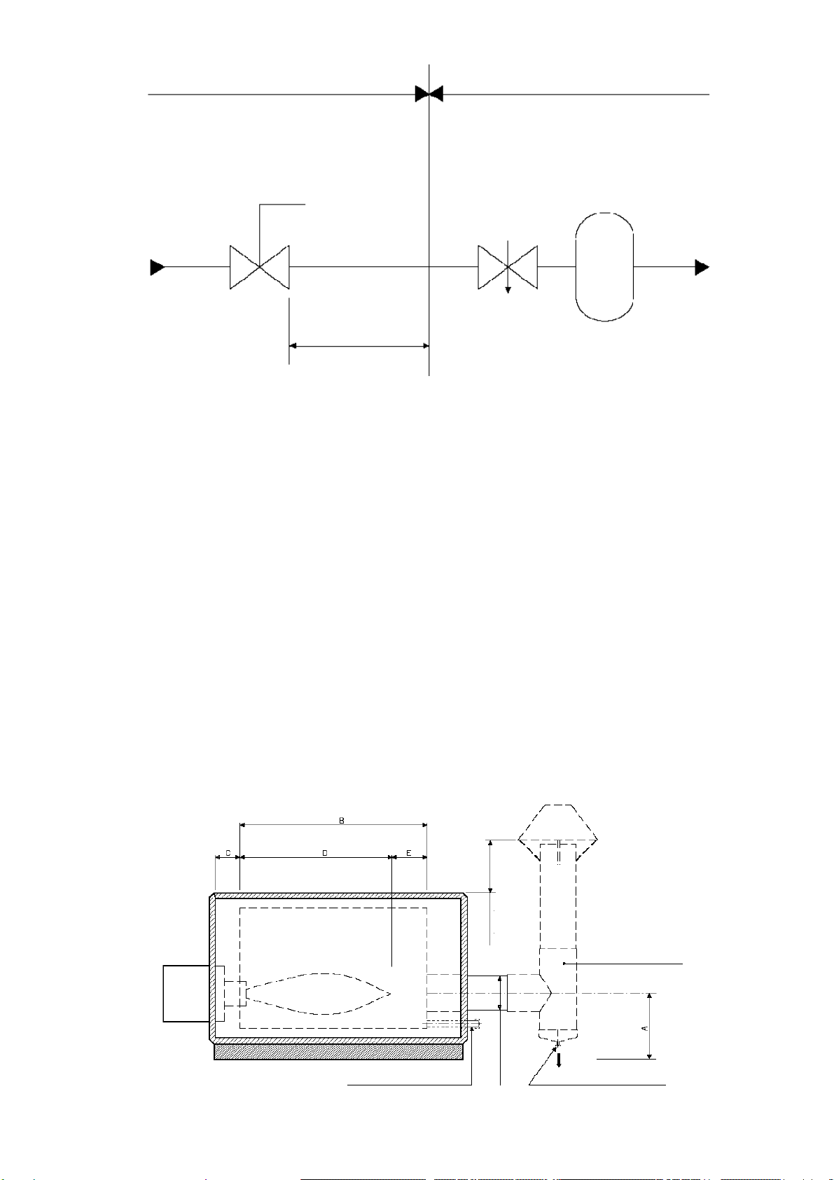
SELECTING THE BUFFER CAPACITY
The volume of the buffer tank + the volume of the pipework (expansion valve at the consumption point) must be based on the
maximum flow of the installation, at least: BP (16 to 21 mbar) 2 litres per Nm3
MP (0.06 to 4 bar) 1 litre per Nm3
NOTE: the buffer capacity does not compensate for undersized pipework.
Required buffer capacity in litres based on the max. flow in Nm3/h
Gas flow rate Nm
3
/h 6 10 16 25 40 65 100 160 250 400 650 1000
Buffer volume LP pressure 12 20 32 50 80 130 200 320 500 800 1300 2000
Buffer volume MP pressure 6 10 16 25 40 65 100 160 250 400 650 1000
8
