CIMCON Lighting NearSky 360 V2.0 User manual

CIMCON LIGHTING Inc.
Nearsky360 System User Guide
Doc Version: V3.0
Doc Date : 25-MAR-2019
For internal use only Page 1
NearSky™ 360 V2.0
User Guide
No part of this document may be reproduced or transmitted in any form or by any means, electronic or mechanical,
for any purpose, without the express written permission of CIMCON Lighting, Inc. Information in this document is
subject to change without notice. CIMCON Lighting, Inc. may have patents or pending patent applications, trade-
marks, copyrights, or other intellectual property rights covering subject matter in this document. The furnishing of
this document does not give you license to these patents, trademarks, copyrights, or other intellectual property ex-
cept as expressly provided in any written license agreement from CIMCON Lighting, Inc.
© 2000 - 2018 CIMCON Lighting, Inc.
All rights reserved.

CIMCON LIGHTING Inc.
Nearsky360 System User Guide
Doc Version: V3.0
Doc Date : 25-MAR-2019
For internal use only Page 2
Revision history:
Ver-
Rev
Date
Author
Changes
Reviewed by
Approved by
1.0
28th Mar, 2019
2.0
20 APR 19
Block diagram up-
dated
3.0
23 APR 19
Page 8 updated
CIMCON LIGHTING Inc.
Nearsky360 System User Guide
Doc Version: V3.0
Doc Date : 25-MAR-2019
For internal use only Page 3
Installation Guide
How to connect peripheral devices with NearSky 360
Step-1: Connect POE compatible camera with connector “LAN2”as shown in below snapshot.
Step-2: Connect Modbus supported sensor with NearSky 360 as per below snapshot.
Please refer below snapshot for pin details of external sensor connector
LAN2
RS-485/Modbus

CIMCON LIGHTING Inc.
Nearsky360 System User Guide
Doc Version: V3.0
Doc Date : 25-MAR-2019
For internal use only Page 4
Step-3: Connect USB device as per below snapshot.
Step-4: Connect NearSky 360 with LAN network for Ethernet backhaul at connector “LAN1”
USB
LAN1

CIMCON LIGHTING Inc.
Nearsky360 System User Guide
Doc Version: V3.0
Doc Date : 25-MAR-2019
For internal use only Page 5
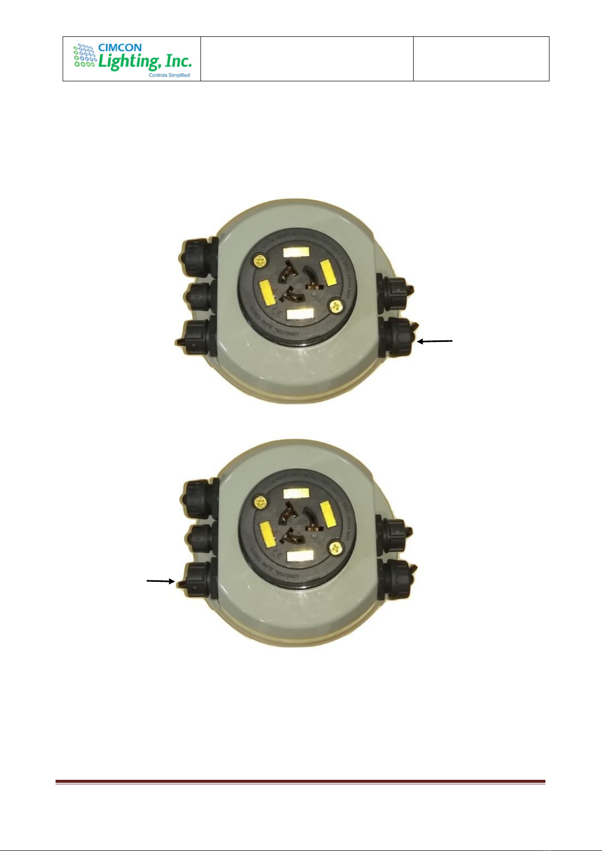
Step-5: Connect 4 pin AC power out connector supplied with unit for external sensor powering.
Mechanical Dimension
AC Power Out

CIMCON LIGHTING Inc.
Nearsky360 System User Guide
Doc Version: V3.0
Doc Date : 25-MAR-2019
For internal use only Page 6
Wiring Diagram
Installation

CIMCON LIGHTING Inc.
Nearsky360 System User Guide
Doc Version: V3.0
Doc Date : 25-MAR-2019
For internal use only Page 7
NS360 V2 Block Diagram
CIMCON LIGHTING Inc.
Nearsky360 System User Guide
Doc Version: V3.0
Doc Date : 25-MAR-2019
For internal use only Page 8
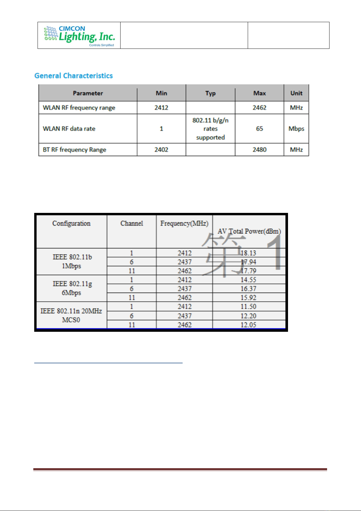
Transmit Power:
Changing Wi-Fi parameters or software updates
Initial user ID and Password will be assigned to authentic user that can access the device and
further manage Wi-Fi user ID, password, IP address etc. later. But Wi-Fi parameters, i.e.
Channel, Power etc., no one can access OR change it. Same is secured through security key
which is generated and managed by CIMCON only if needed to change in future.
Because CIMCON host third party controller module having this WLAN/Bluetooth module
assembled over it, there is no access to change OR offer any user interface from which this can
be changed. This is always default settings we use.

CIMCON LIGHTING Inc.
Nearsky360 System User Guide
Doc Version: V3.0
Doc Date : 25-MAR-2019
For internal use only Page 9
Module part used is ‘TiWi-BLE’ from LSR: It is integrated Transceiver Modules for WLAN 802.11
b/g/n, Bluetooth, Bluetooth Low Energy (BLE)
CIMCON LIGHTING Inc.
Nearsky360 System User Guide
Doc Version: V3.0
Doc Date : 25-MAR-2019
For internal use only Page 10

CIMCON LIGHTING Inc.
Nearsky360 System User Guide
Doc Version: V3.0
Doc Date : 25-MAR-2019
For internal use only Page 11

CIMCON LIGHTING Inc.
Nearsky360 System User Guide
Doc Version: V3.0
Doc Date : 25-MAR-2019
For internal use only Page 12
FCC Statement:
FCC ID: 2ALSZ-CLNSV2
This device complies with Part 15 of the FCC Rules. Operation is subject to following two
conditions:
1. this device may not cause harmful interference, and
2. this device must accept any interference received, including interference that may
cause undesired operation.
FCC 15.21 statement
-Any changes or modifications not expressly approved by the party responsible for
compliance could void the authority to operate equipment.
-This device and its antenna must not be co-
located or operating in conjunction with any other antenna or transmitter.
-For product available in the USA/Canada market, only channel 1~11 can be operated.
Selection of other channels is not possible
-
MPE Warning
Mobile Device
This equipment complies with FCC radiation exposure limits set forth for an uncontrolled
environment. This equipment should be installed and operated with minimum distance 20cm
between the radiator & your body.
Antenna Information WLAN / Bluetooth:
Both WLAN and Bluetooth share the same antenna port.
NS360V2 has One antenna inside, Both WLAN and Bluetooth share the same antenna port for TX
and RX
This device has been designed to operate with the antenna(s) listed below and having a maximum
gain of 3.32dBi (on plastic).
Part no: FXP830.07.0100C
Manufacturer: Taoglas

CIMCON LIGHTING Inc.
Nearsky360 System User Guide
Doc Version: V3.0
Doc Date : 25-MAR-2019
For internal use only Page 13
Description: FXP.830 Freedom Wi-Fi 2.4/5 GHz Dipole Antenna. Ground-plane Independent. IPEX
MHF1 Connector (U.FL compatible).
Table of contents
Popular Lighting Equipment manuals by other brands


American DJ
American DJ Tri Image User instructions

Code 3
Code 3 C5550 Series Installation and operation instructions

EuroLite
EuroLite LED PFE-100 RGBW Profile Spot user manual

hidealite
hidealite Comfort Track Series quick guide

Equinox Systems
Equinox Systems GEMINI user manual

PROEL
PROEL PLST15H user manual


