Cine Gears 600MP User manual

Wireless Video Transmission System
600MP Instruction Manual
R
CINEGEARS GHOST - EYE
WIRELESS VIDEO KIT


Statement of Conditions
In the interest of improving internal design, operational function, and/or
reliability, Cine Gears Inc. reserves the right to make changes to the products
described in this document without notice.
Cine Gears Inc. does not assume any liability that may occur due to the use or
application of the product(s) or circuit layout(s) described herein.
FCC Compliance Notice: Radio Frequency Notice
The device has met the FCC 15.247 requirement. In order to comply with the
FCC RF exposure requirement, the user must keep 20cm away from the
antenna. This device has been tested and found to comply with the limits for a
Class B digital device, pursuant to part 15 of the FCC Rules. These limits are
designed to provide reasonable protection against harmful interference in a
residential installation. This device generates, uses, and can radiate radio
frequency energy and, if not installed and used in accordance with the
instructions, may cause harmful interference to radio communications. However,
there is no guarantee that interference will not occur in the particular installation.
If this device does cause harmful interference to radio or television reception,
which can be determined by turning the equipment off and on, the user is
encouraged to try to correct the interference by one or more of the following
measures:
•Reorient or relocate the receiving antenna.
•Increase the separation between the equipment and receiver.
•Connect the equipment into an outlet on a circuit different from that to which
the receiver is connected.
•Consult the dealer or an experienced radio/TV technician for help.

Information to the user
The user’s manual or instruction manual for an intentional or unintentional
radiator shall caution the user that changes or modifications not expressly
approved by the party is responsible for compliance and could void the
user’s authority to operate the equipment.
In cases where the manual is provided only in a form other than paper such
as on a computer disk or over the Internet, the information required by this
section may be included in the manual provided and could be accessed in
the alternative form.

Contents
■
Safe Operation
2
3
■
Accessories
4
What Comes in a Standard Dual-Axis Head Kit
4
Item Description
5
■
User Manual
7
Basic Setup of Head
7
Camera setup/balance
7
Basic Controller Functions
8
■
Disclaimers
9
■
Customer Support
11
■
Introduction Introduction and Specification

Features
1
. Uses License-Free 5GHz ISM frequency band, maximum 10 frequency channels
selection, coexist with WIFI.
. Highest resolution 10 bits color depth 4:4:4, 1080p 60FPS HDMI and SD/HD/3G
SDI input and output, HDMI SDI cross conversion is supported.
. Support wireless 10 bit HD video with no compression and no delay up to
1150FT(350M). Uncompromised picture quality with very low latency, <1ms.
. Supports point to point, and point to multi points network topology, one transmitter
can be connected up to 4 receivers.
. Supports professional audio format include Dolby True HD, DTS-master, etc.
. AES-128/256 encryption with air interface HD video data stream.
. Wide range power voltage input, compatible with most kinds of camera batteries.
Sony F970 battery buckle, convenient for field battery install and replacement.
. All input and output ports have +-8 kV ESD protection level(HBM, contact
discharge).
. Plug & Play – no software is required.
. Professional standard 2-pin LEMO power plugs.
. Each RX(receiver) paired to the unique TX(transmitter) in factory.
. Industrial metal and plastic case with robust cooling and durability.
. RX built-in directional antenna.
. OLED screen display power status, Temperature, Fan on/off, RSSI, Frequency
Channel, Resolution, Video Status.
. The hard carrying case provide water and shock proof to product.

2
Receiver Diagram
4
1
2
8
7
Receiver:
1:HDMI Output
2:Power On/Off
3:DC Input
4:Frequency Channel Up 5:
Frequency Channel Confirm
(press and hold to turn on or off the fan)
6:Frequency Channel Down
7:SDI Output1
8:SDI Output2
56
3

Transmitter Diagram
3
5
8
2
3
Transmitter:
1:Power On/Off
2:USB port for firmware
update
3:Audio input
4:DC Input
5:Frequency Channel Up 6:
Frequency Channel Confirm
(press and hold to turn on or off the fan)
7:Frequency Channel Down
8:HDMI Input
9:SDI Input
10:SDI Loop-out
4
1
6
7
9
10

Camera
Installation
4
Receiver
Transmitter
Suggest installing receiver 2+ meters high from ground
Ground
Director
External Battery
Lemo Cable
Cameraman
Monitor
The best reception angel
(transmitter and receiver face-to-
face)
External Battery
VIDEO OUT
VIDEO IN
Suggest installing receiver 1.7+ meters high from ground
Lemo Cable

Screen Instruction
5
1
7
4
35 C
0
CH. VIDEO
1080P60
23
5
6
Menu description:
1:Battery Level
2:Working Temperature
3:Fan status
4:RSSI
5:Frequency Channel
6:Resolution
7:Video Status
Strong
Middle
Weak

6
The video
quality is bad
The RSSI is
good but the
video quality is
bad
The system
can’t establish
link
The working
distance can’t
reach 244M
Step 1 Step 2 Step 3 Step 4
1
If the transmission system
can’t establish link at long
distance but works well at
shorter distance. Please
check if the transmitter
and receiver under
specified working
distance. And if the
transmitter and receiver
set at the same frequency. 2
If the problem is not
solved after step 1.
Please restart the
transmitter and receiver. 3
If the problem is not
solved after step 2. Please
shorten distance and
check the link status. 4
If established link at
shorter distance.
Please go to next
guide.
1234
If established link at
shorter distance. Please
check if the antennas
are screwed tightly.
The transmitter and
receiver are NOT parallel
to each other. The 2 TX
antennas’ angle is 45°.
Make sure no big obstacle
between transmitter and
receiver.
If the problem is not
solved after step 1.
Please change the
frequency and check
the link status. If the
link is improved. The
problem is caused by
interference. 。
If the problem is not
solved after step 2.
Please replace the
antennas with new
ones and try again.
If the problem is not
solved after step 3.
Please contact with us
for RMA.
1234
Please make sure the
distance is within the
maximum working
distance. The transmitter
and receiver are NOT
parallel to each other.
The 2 TX antennas’
angle is 45°. If there is
big obstacle between
transmitter and receiver,
please shorten distance.
If the RSSI on receiver
has more than 3 lights
on, please go to next
step. If the RSSI has less
than 3 lights on. Please
change the frequency
and check the video
quality.
If the video quality is
not improved after
changing frequency.
Please replace antennas
with new ones or try
other system with
good performance
before.
If the other system has
the same problem.
Please move to other
place and try again.
If the old system works
well and the new system
still has problem after
changing place. Please
contact with us for RMA.
1234
The RSSI is good but
the video quality is bad.
Please make sure the
distance is within the
maximum working
distance and the 2 TX
antennas’ angle is 45°,
the transmitter and
receiver are NOT parallel
to each other.
If the problem is not
solved after step 1.
Please check the input
video resolution.
Downgrade the
resolution and check
again. 1080i’s working
distance is longer than
1080p with the same
video quality.
If the video quality is
not improved after
downgrading resolution.
Please shorten distance
by half. If the video
quality is improved.
Please record the distance
when the video quality
becoming bad.
If the video quality is
not improved after
shortening distance.
Please change the
frequency. If it’s still
not improved, please
contact with us for
RMA.
Troubleshooting Guide
If the transmission system worked well at short distance, but has problem at long
distance or the video quality is not good. Please follow instructions as below:

Specification
7
Transmitter Receiver
Interface
HDMI output(Type A female);
SDI output*2(BNC female));
DC input (2-pin LEMO female)
HDMI input(Type A female); SDI
input(BNC female); SDI loop-
out(BNC female); 2 antenna
port(PR-SMA male); DC input (2-
pin LEMO female)
7-36V DC
Supply Voltage Range 7-36V DC
<6.5W
Power Consumption <6W
(L x W x H): 66.5*124*27mm
Size (L x W x H): 95.4*153.2*25.7mm
HDMI:525i, 625i, 720p 50/59.
94/60,1080i 50/59.94/60,
1080p23.98/24/25/29.9/30/
50/59.94/60;HDMI Type A SDI:
3G, HD, and SD-SDI
(auto-selected)
SMPTE-259/274/292/296/
372/424/425;1x BNC
Input Video Format
/
HDMI:525i, 625i, 720p 50/59.
94/60,1080i 50/59.94/60,
1080p23.98/24/25/29.9/30/
50/59.94/60;HDMI Type A SDI:
3G, HD, and SD-SDI
(auto-selected)
SMPTE-259/274/292/296/
372/424/425;1x BNC
Output Video Format
SDI:3G, HD, and SD-SDI
(auto-selected)
SMPTE-259/274/292/296/
372/424/425;1x BNC
Frequency Band 5.1-5.9GHz,configurable with China,
North America, Europe, etc
OFDM 16QAM
Modulation Mode OFDM 16QAM
Maximum 16dBm
Transmission Power /
/
Receiver Sensitivity -75dBm
20/40MHz
Occupied Bandwidth 20/40MHz
0-40℃(working temperature);
-20-60℃(storage temperature)
Temperature Range
Optimal range 800FT/244M
Maximum
range:1150FT(350M)
Transmission Range
5.1-5.9GHz,configurable with China,
North America, Europe, etc
0-40℃(working temperature);
-20-60℃(storage temperature)
Optimal range 800FT/244M
Maximum range:
1150FT(350M)
250g
Weight 300g

Installation
8
1) Ensure the video source output of the camera is OK, and the HD monitor is
powered on and switched to connected video input port.
2) Ensure 2 TX antennas are installed. For optimal results set the dual
antennas in the form of a “V” and maintain unobstructed line of sight
between transmitter and receiver. Below figure for your reference:
3) Ensure all input, output SDI or HDMI cables are connected.
4) Ensure both transmitter and receiver are powered via battery or DC input. Then
turn on power switch of the transmitter and receiver respectively. The screen will
light.
5) Ensure the transmitter and receiver is set with the same frequency.
6) If the camera is on and video input is OK, TX screen will show HDMI or SDI.
9
Installation
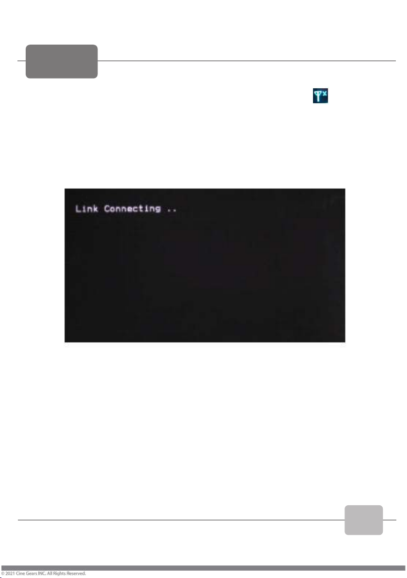
7) Before RX finished wireless link with TX, the RX screen displays and NO
VIDEO;
when wireless link is done, RSSI indicators will indicate the signal strength. If the
receiver detects wireless video signal, the screen will display VIDEO. Before that,
If SDI or HDMI video out port of the receiver has HD monitor connected, it will
display an OSD of Link connecting…… as in the figure below.
8) The system will spend 10 seconds constructing the link, depending on link
strength and the signal channel condition. When wireless link is established the
screen will display the current wireless signal strength, VIDEO, and the
connected HD monitor will be playing the real-time video and audio.

10
Frequency Selection
The wireless transmission system works in the 5.1-5.9GHz frequency band
and can be flexibly configured to other licensed or ISM bands to accommodate
different global regions. The front panel of the transmitter and receiver features
frequency channel selection and confirmation buttons (see below illustration),
which provides a maximum of 10 workable frequency channels, and supports a
maximum of 4 simultaneous receiver units.
Frequency
Selection
Buttons

11
●Do not expose this device to extreme hot, cold, dusty or humid
environments.
●Do not scratch the device with sharp objects.
●Do not drop this device from high place, as this may cause hardware
damage.
●This device is designed for non-waterproofing. Please do not allow any liquid
to penetrate into the device.
●Do not attempt to dismantle, open or repair this device yourself, as this may
cause permanent damage to the device.
Warning

Disclaimers
■
FCC Statement
This equipment has been tested and found to comply with the limits for a Class B digital device, pursuant
to part 15 of the FCC rules. These limits are designed to provide reasonable protection against harmful
interference in a residential installation. This equipment generates, uses and can radiate radio frequency
energy. If not installed and used in accordance with the instructions, IT may cause harmful interference
to radio communications. However, there is no guarantee that interference will not occur in a particular
installation. If this equipment does cause harmful interference to radio or television reception, which can
be determined by turning the equipment off and on, the user is encouraged to try to correct the
interference by one or more of the following measures:
-Reorient or relocate the receiving antenna.
-Increase the separation between the equipment and receiver.
-Connect the equipment into an outlet on a circuit different from that to which the receiver is connected.
-- Consult the dealer or an experienced radio/TV technician for help.
To assure continued compliance, any changes or modifications does not expressly approved by the party
responsible for compliance could void the user's authority to operate this equipment. (Example use only
shielded interface cables when connecting to computer or peripheral devices).
FCC Radiation Exposure Statement
This equipment complies with FCC RF radiation exposure limits set forth for an uncontrolled
environment. This transmitter must not be co-located or operating in conjunction with any other antenna
or transmitter. This equipment complies with part 15 of the FCC Rules.
Operation is subject to the following two conditions:
(1)
This device may not cause harmful interference.
(2)
This device must accept any interference received, including interference that may cause undesired
operation.
Cautions
The manufacturer is not responsible for any radio or TV interference caused by unauthorized
modifications to this equipment. Such modifications could void the user authority to operate
the equipment.

Disclaimers
■
Terms and Conditions
Congratulations on purchasing your new CINEGEARS product. Please read this manual carefully before
using the product. By using this product, you hereby agree to this disclaimer and signify that you have read it
in full. You agree that you are responsible for your own conduct and any content created while using
CINEGEARS products, and for any consequence. You agree to use this product only for purposes that are
proper and in accordance with local regulations, terms and any applicable polices and guidelines.
By reading this disclaimer, you also agree:
1.
Any part of this disclaimer is subject to change without prior notice. Refer to:
WWW.CINEGEARS.COM for the latest version.
2.
CINEGEARS reserves the right of final interpretation of this disclaimer.
CINEGEARS and the Dual Axis Head are registered trademarks of Littlecent International Trading Corp.
Names of product, brand, etc. appearing in this manual are trademarks or registered trademarks of their
respective owner companies. This product and manual are copyrighted by CINEGEARS with all rights
reserved. No part of this product or manual shall be reproduced in any form without the prior written consent
or authorization of CINEGEARS.

About Cine Gears Inc.
Cine Gears Inc. is an industry leading company that design and manufactures digital wireless follow focus
systems, lens control systems, camera motion control systems and accessories for film and broadcast
industry. As a big believer in the power of creativity and ideas, we designed the Pegasus cablecam, the
wireless motor drive that integrated a built in wireless transmitter, and the wireless finger wheel controller.
The Cine Gears Inc. wireless lens control system has the international CE certification on all its equipment.
Cine Gears lens control system can achieve the finest minutia of focus pulling, with extreme accuracy and
control. This very same technology is what drives the Pegasus for ultra-smooth, highly controlled,
programmed movement.
We have been working from Vancouver, BC for over 10 years and our equipment has been used on
hundreds of movies. Filmmakers of all experience levels will benefit greatly from our simple, professional,
and well rounded product line. We work hard so our products can help you get the perfect shot with greater
ease, less crew, and less wires.
Customer Support
If you encounter any issues with any of our products please contact us
directly
via
the details provided below. DO NOT CONTACT THE RETAIL
STORE.
CINE GEARS INC. (USA) 8105
Birch Bay S
q
uare Street. Unit
202.
Blaine,
W
A, 98230. USA Tel:
1 206 660 3267
Toll Free: 1 800 693 8883
CINE GEARS INC. (Canada)
2nd floor 2010-9111 Beckwith
Road Richmond, BC V6X
1V7, Canada Tel: 1 604 243
9995
Table of contents


