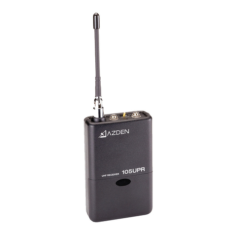
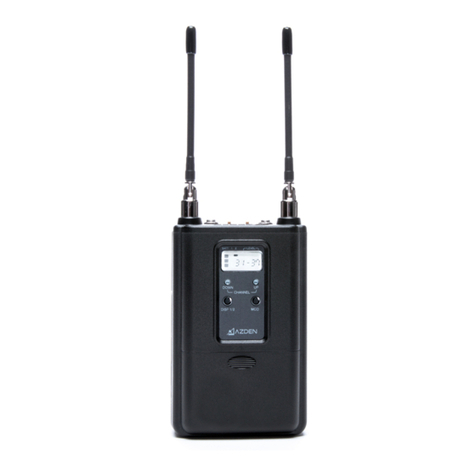
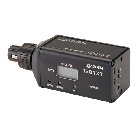
Azden 105UPR User manual

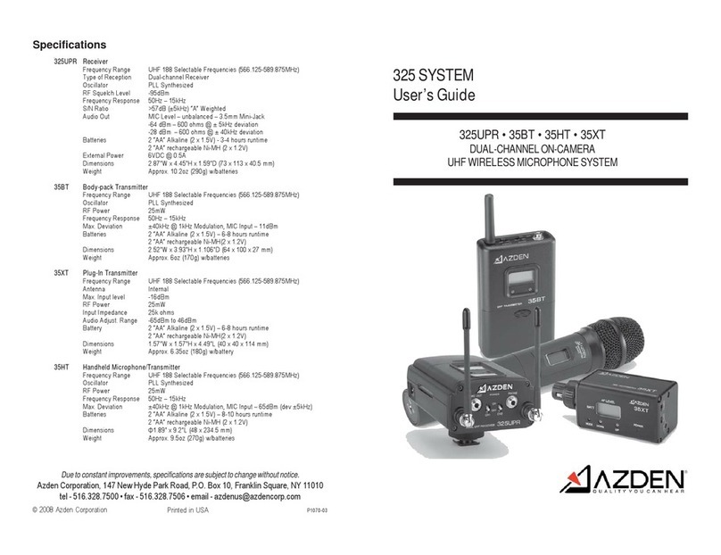
105
SYSTEM
User's Guide
105UPR 15BT 15HT 15XT
ON-CAMERA
UHFWIRELESS MICROPHONESYSTEM
&EDEN'
/
QUALITY YOU
CAN
HEAR


Thank you for purchasingAzden's 105wirelessmicrophonesystem. Dependingon
which systemyou ordered this packagewill containone or more of the following compo-
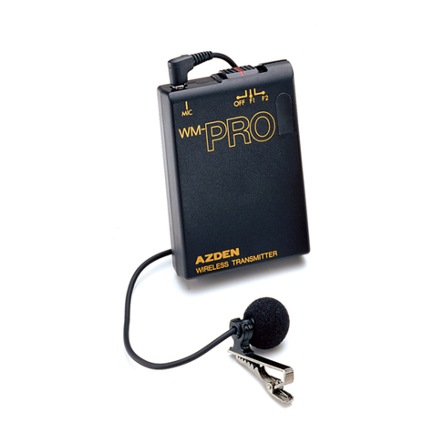
nents:the 105UPR receiver,the 15BTbody-pack transmitterwith EX-503Llavalier mi-
crophone,the 15XTXLR plug-in transmitterandlor the 15HThandheldmicrophone
transmitter. This equipment isdesignedprimarilyfor video cameras but is usable with
most electronic componentshaving a microphonelevel input.The 105UPRallows you to
"receive"audio from one transmitterat a time.
RECEIVER (105UPR)
*
(1) Removethe batterycompartmentlid bysliding it down.
(2) Inserttwo fresh Alkaline* "AA" batteriesinto the compartment. Makesure the battery
.2,
polarityiscorrect as markedinside the battery compartment.
(3) POWER:
Switchesthe receiver "ON" or "OFF".
(4)
MIC OUTjack:
The 105UPRis suppliedwith a mini-to-minicable.
For minijack microphoneinputs: Usethe supplied mini-to-minicable. Plug one
end of the cable intothe receiverand the other end of the cable into the micro-
phone input of the video camera.
For 3-pin XLR microphoneinputs: Usethe optionalmini-to-XLRcable (MX-1).
Plugthe mini-plugend of the cable intothe receiver (use the screw-downsleeve
to secure itto the receiver)and plugthe XLR end of the cable intothe micro-
phone input of the video camera.
i
(5) FrequencySelection:
Frequencyadjustmentis accomplishedbysettingthe controls inside the battery com-
partment.With the frequency GROUP dial on the left (columnA on the included chart)
you can select any of 10frequencygroups (numbered0-9). With the frequency CHAN-
.1
NEL dial on the right (column B on the includedchart) you can select any of 10frequency
channels (numbered 0-9). There are 92 possiblecombinations.
(6)
PhoneJack:
Plugan earphone into thisjack to monitorthe sound. Thejack is wired to work with either
monoor stereo headphones(youwill hear mono in bothears).
(7)
LED indicator:
This LED turns
RED
when the receiver isturned "ON" and
GREEN
when receivinga
signal from the transformer.

(8) Phone OutputAdjustment: Usingthe supplied tool, turn the screw clockwiseto in-
crease earphone level and counterclockwiseto decrease.
(9) Shoe-Mount:
Attach the 105UPRto the shoe-mountof the video cameraby slidingit into place. Turn
the thumbwheel clockwise to tighten. Reverse this procedureto remove.
(10)Antenna: For best receptionthe antenna should be pointedin an upwardfashion.
Usecaution, and do not force it intothis position.
BODYPACKTRANSMITTER (15BT)
3
(11) Removethe battery compartmentlid bysliding it down.
\
2
(12) Inserttwo fresh
"AA"
Alkaline*batteriesintothe compartment. Makesure the bat-
tery polarity is correct as markedinsidethe batterycompartment.
In additionto the battery, insidethe batterycompartment you will find:
(13) MIC lnput LEVEL Control:
This control enablesyou to adjust the inputlevelof the microphone. Usingthe supplied
tool, turn the dial clockwiseto increase,or counterclockwiseto decrease the input level.
(14) POWER:
Switchesthe transmitter "ON"or "OFF",
(15) MIC lnput Jack:
Plugthe supplied EX-503Lmicrophoneinto the MIC inputjack and tighten the collar until
snug (DO NOT OVERTIGHTEN). In addition to the EX-503L, other lapel andlor headset
microphoneswith 3.5mm mini plugs can also beusedwithithe 15BT.
(1
6)
Frequency Selection:
Frequencyadjustmentis accomplished by setting the controls inside the batterycom-
partment.With the frequency GROUP dial on the left (column A on the includedchart)
you can select any of 10frequency groups (numbered 0-9). With the frequency CHAN-
NELdial on the right (column Bon the included chart) you can select any of 10frequency
1;
channels (numbered 0-9). Thereare 92 possible combinations.
i'
(17) Audio Standby:
The AudiolStandby switch ierves as a muteswitch. In the STBY position the audioout-
putfrom the 15BT is mutedwhile in the ON positionaudio is transmitted.
(18) Beltclip

XLR PLUG-IN TRANSMITTER (15XT)
(19) Open the batterycompartment lid and insert 2 fresh "AA" Alkaline batteries.Make
sure the battery polarityiscorrectas marked insidethe batterycompartment
(20) POWER:
Switchesthe transmitter"ON"or "OFF"
(21)AUDIO:
Priorto first turning the 15XT"ON" itis bestto set the AUDIO switch to "OFF". When
'i
you are ready to begintransmitting, switchto
"ON".
The
"OFF"
position acts as a
'mutete"that maintainsthe RF signal but turns off the audio.
(22)MIC ConnectorlLockingRing:
This 3-pinXLR connectoris the microphone input. Any low impedance microphone
with a correspondingconnectorcan beattached here. Once the microphone is plugged
intothe 15XTthe lockingringshould be rotatedclockwiseuntilsnug. To remove the
microphone,first rotatethe locking ringcounterclockwiseand then, while pressing the
XLR release, pullthe microphoneaway from the 15XT.
(23) MIC Input LEVEL Control:
The MIC input LEVEL controlenablesyou to adjust the inpdlevel.ofthe connected
microphone. Usingthe supplied tool, turn the dialclockwiseto increase, or counter-
clockwiseto decreasethe inputlevel.
(24) Frequency Selection:
Frequencyadjustmentis accomplishedbysetting the controls ingMe the battery com-
partment.With the frequency GROUPdialon the left(column
A
on the included chart)
you can select any of 10 frequency groups (numbered0-9).With the frequency
CHAN-
NELdial on the right (column
B
on the included chart) you can select any of 10fre-
quency channels (numbered 0-9).There are 92 possiblecombinations.

HANDHELD MlCROPHONErTRANSMlTTER(15HT)
(24)Removethebatterycompartmentcover byrotatingitcounterclockwiseandslidingit
down.
(25) InserttwofreshAlkaline*"AA"batteries*intothecompartment. Makesure
the
battery
polarityiscorrectasmarkedinsidethebatterycompartment.
Inthebatterycompartmentyou.willalsofind#26 and#27:
(26)MIC LEVEL Control:
The MICLEVELcontrolenablesyouto adjusttheaudiolevelofthe microphone. Usingthe
suppliedtool, turn thedialclockwiseto increase,orcounterclockwiseto decreasethe
microphone'saudio level.
(27)
FrequencySelection:
Frequencyadjustmentisaccomplishedbysettingthecontrolsinside'thebattery
compartment.Withthefrequency
GROUP
dialon theleft(columnAon the includedchart)
youcanselectanyof 10frequencygroups(numbered0-9).With thefrequency CHANNEL
dialon theright(column
B
on theincludedchart)youcanselectany'of10frequency
channels(numbered0-9).Thereare
92
possiblecombinations.

Operatingthe system
Becausethis isafrequencyagilesystem,thereceiverandtransmitter mustbeon the same
Receivenransmitfrequency. Followthe instruction#5,16,24 and 27. Makesure boththe
receiverandtransmitterareon thesamechannel.
105UPR Receiver
After installingnewbatteries,mountthe receivertoyourvideocamerawith thesupplied
shoemountor hook
&
loopfastener. Connecttheoutputcabletothereceiverandtothe
microphoneinputonthevide mmera. Switchthe 105UPRto"ON"and the power
6
indicator(7)shouldcomeo
I?
,~ed'?
Ifitdoesn't, check thebatteries.When the 105UPR
receivesa signalfrom thetransmitter the
LED
indicatorwill changetmen:Ifitdoes not,
4
makesureboththereceiverandtransmitter are on matchingchannhs:
15BTTransmitter
Pluginthe suppliedlapelmicrophoneand clip itto your subject. Themicrophoneshouldbe
placed4-12inchesfrom your subject'smouth. Clip the transmittertoabeltusingthe
suppliedbelt-clipor placeitin a pocket. Switchthe 15BTto "ON"andthepowerindicator
shouldcomeon. Ifitdoes not,checkthe batteries. Havesomeonespeak intothe
microphoneas youmonitorthesoundthrough the receiver'sphoneoutput. Ifthe sound is
distortedlowerthe MICinputlevelon thetransmitter. Ifthereisnotenough volume raisethe
MICinputlevelon thetransmitter.
;
15XTTransmitter
Switchthe transmitterto "ONnandthepowerindicatorshouldcomeon. Ifitdoesnot,check
thebatteries. Havesomeonespeak intothemicrophoneas youmonitorthe sound through
thecamera'smonitoroutput. Ifthesound isdistorted lowerthe levelcontrolonthe
transmitter. Ifthereisnotenoughgain raisethelevelcontrolon thetransmitter.
35HTTransmitter
Switchthetransmitterto"ONnandthepower1indicatorshouldcomeon. Ifitdoes not,check
thebatteries. Havesomeone speak intothe microphoneas you monitorthesound through
thecamera'smonitoroutput. Ifthe sound isdistortedlowerthe levelcontrolonthe
transmitter. Ifthereisnotenoughgainraisethelevelcontrolon thetransmitter.
Important information
Licensing of this, or any kdenwireless equipment Is the user's responsibility. The ability to receive a license depends largely on the
user's classification, application and frequency. Contact the appropriate agency (FCC in the
US)
for further information.
Thesedevices comply with Part
15
of the FCC Rules. Operation is subject
to
Ule
following
two
conditions:
(1)
These devices may not
cause harmful interference, and
(2)
These devices must accept any interference received, Including interference that may cause
undesired operation.
NOTE: The manufacturer is not responsible for any radio or
TV
interference caused by unauthorized mdifications to this equipment
Such modifications could widthe usek authority to operate the equipment.
These devices and their antenna@)must not be co.located or operated in conjunction with any other antennaor transmitter.
5

Specifications
IOSUPR Receiver
Frequency Range
Type of Reception
Oscillator
RFSquelch Level
Frequency Response
SIN Ratio
Audio Out
Batteries
Dimensions
Weight
UHF92 Selectable Frequencies (566.25-589.75MHz)
FM
PLL Synthesized.
-92dBm
50Hz
-
12kHz
>57dB (~5kHz)
'A"
Weighted
MIC.Level
-
Balanced
-
3.5mm Mini-Jack
-57 bdBm-600
?
@
i
5kHz deviation
2
'AA"
Alkaline (2x 1.5V)
-
6-8 hours runtime
2
'AA"
rechargeable Ni-MH (2 x 1.2V)
2.48.W x 3.86"H
x
1.06"D (63
x
98 x 27 mm)
Approx. 6.35oz(180g) whatteries
1SBT Body-pack Transmitter
Frequency Range UHF 92 Selectable Frequencies (566.25-589.75MHz)
Oscillator PLL Synthesized
RF Power 25mW
Frequency Response 50Hz
-
15kHz
Max. Deviation 24OkHz
@
lkHzModulation, MIC Input
-
IldBm
Batteries 2 "AA"Alkaline (2x 1.5V)
-
6-8 hours runtime
2 'AA" rechargeable Ni-MH(2
x
1.2V)
Dimensions 2.48"W x 3.86"H x 1.06"D (63
x
98 x 27 mm)
Weight Approx. 5.640~(160g)whatteries
15XT Plug-InTransmitter
Frequency Range UHF92 Selectable Frequencies (566.25-589.75MHz)
Oscillator PLL Synthesized
Antenna Internal
/'
RF Power 25mW
Frequency Response 50Hz
-
12kHz
Reference Deviation ~5kHz(-60dBm
-
IkHzinput)
Battery 2 "AA"Alkaline (2x 1.5V)
-
6-8 hours runtime
2
"AA"
rechargeable Ni-MH(2 x 1.2V)
Dimensions 1.57"W x 1.57"H x 4.49"L (40 x 40 x 114 mm)
Weight Approx. 6.3502 (1809)whattery
15HT Handheld MicrophonelTransmitter
Frequency Range UHF 92 Selectable Frequencies (566.25-589.75MHz)
Oscillator PLL Synthesized
RF Power 25mW
Frequency Response 50Hz
-
12kHz
Reference Deviation *5kHz (-6OdBm
-
IkHzinput))
Batteries 2 'AA" Alkaline (2x 1.5V) -6-8 hours runtime
2 'AA" rechargeableNi-MH (2x 1.2V)
Dimensions 01.73" x 9.05"L (44 x 230 mm)
Weight Approx. 4.580~(1309)wbatteries
Duetoconstantimprovements,specificationsaresubjecttochangewithoutnotice.
Azden Corporation, 147New HydePark Road, P.O. Box 10, Franklin Square, NY 11010
tel
-
516.328.7500*fax
-
516.328.7506 email
-
O
2008 Azden Corporation Printed in USA
PI
070-03

105
Series
Frequency
Chart
Other manuals for 105UPR
3
This manual suits for next models
3
Table of contents
Other Azden Microphone System manuals

Azden
Azden PRO-XR User manual

Azden
Azden 100UPR User manual

Azden
Azden 500UDR User manual

Azden
Azden WMT-PRO User manual

Azden
Azden 310UDR User manual

Azden
Azden EX-503 User manual

Azden
Azden i-Coustics PRO-XD User manual

Azden
Azden WHX-PRO User manual

Azden
Azden Body-pack Transmitter 35BT User manual

Azden
Azden 200R User manual