Circor Leslie F-340LDW Assembly instructions

Installation, Operating and
Maintenance Instructions
90/4.5.5
Rev. 0
Constantemp Double Wall Low pressure steam-water Heater
F-340LDW,F-640LDW, F-940LDW and F-1240LDW
Table of Contents
SECTION I...................................................................................................................................................................................2
INSTALLATION....................................................................................................................................................................... 2
OPERATION.............................................................................................................................................................................2
SECTION II..................................................................................................................................................................................2
START-UP PROCEDURE........................................................................................................................................................2
TO DRAIN UNIT FOR PROLONGED SHUT-DOWN ...........................................................................................................3
SECTION III................................................................................................................................................................................7
MAINTENANCE OF SYSTEM COMPONENTS....................................................................................................................7
ACTUATOR ASSEMBLY........................................................................................................................................................2
VALVE PLUG ASSEMBLY..................................................................................................................................................... 2
CONTROL VALVE ASSEMBLY ............................................................................................................................................2
MAINTENANCE OF SYSTEM COMPONENTS HEAT EXCHANGER...............................................................................2
SECTION IV - TROUBLE SHOOTING GUIDE.....................................................................................................................2
Recirculating Systems................................................................................................................................................................2
Heat Exchanger and Blending Valve .........................................................................................................................................3
Table of Figures
FIGURE 1.....................................................................................................................................................................................4
FIGURE 2.....................................................................................................................................................................................6
Figure 3 ......................................................................................................................................................................................... 2
Figure 5 ......................................................................................................................................................................................... 2
Figure 6 ......................................................................................................................................................................................... 2
F-340LDW ....................................................................................................................................................................................2
F-640LDW ....................................................................................................................................................................................3
F-940LDW ....................................................................................................................................................................................4
F-1240LDW ..................................................................................................................................................................................5

Installation, Operating and
Maintenance Instructions
90/4.5.5
Rev. 0
SECTION I
INSTALLATION
1. HEATER MAY BE WALL OF FLOOR STAND
MOUNTED - Allow recommended clearances over,
under and around heater shown on Piping Layout
Drawing for maintenance purposes; page 7-8.
2. CONNECTION OF STEAM TRAP DISCHARGE
PIPING – The Steam trap must discharge onto an
atmospheric or sub-atmospheric system. The
Condensate should be free flowing with no lift. If
steam supply pressure is greater than 5 psig, then the
MAXIMUM elevation of the trap discharge line above
the Heater is to be no more than 6 feet. If the steam
supply pressure can vary or if the maximum efficiency
is required, the best results under all operating
conditions will be obtained if the trap discharges to an
atmospheric or sub-atmospheric line located below the
level of the trap.
3. A safety valve must be installed in inlet steam piping
if steam pressure to Heater can exceed, 150 psig for
steel exchangers. See Piping Installation Drawing No.
35513C for details.
4. A pressure gauge must be installed in the inlet steam
piping close to Heater.
5. A spring loaded relief valve is incorporated in the
blending valve to relieve excess pressure that can be
caused by thermal expansion of water during a shut-
off or no load condition.
6. Install a thermometer in hot water outlet piping close
to Heater.
OPERATION
1. Normally a heat exchanger having a constant
fixed steam supply pressure and a variable output
flow demand allows water temperature to
increase as flow demand decreased, and decrease
as flow demand increases. This Heater has a
unique adjustable gain feature incorporated in the
Heater control system that automatically
compensates in most part for the wide
temperature variations normally encountered
when an uncontrolled steam supply pressure is
used. Compensation is accomplished by re-
proportioning the blend ratio of hot and cold
water on an automatic Feedforward basis. The
blending valve incorporated a third window
which is normally closed by a seal plate
assembly. In the event that some dirt or foreign
material enters the blending valve preventing its
movement, the yielding spring will allow the
diaphragm and stem to move upward, opening
the third window. As seal plate uncovers third
window, it allows cold water to flow into the
blended mix, thus preventing water from
becoming overheated.
SECTION II
START-UP PROCEDURE
1. Turn on cold water supply. With no water flow
through heater, slowly open steam stop valve to
heat exchanger making sure traps are functioning
properly to prevent water hammer.
2. Loosen pipe plug in top of heat exchanger casing
and vent all air from casing before re-tightening
pipe plug.
3. Loosen set screw in temperature adjuster (14)
lock nut (13) and move lock nut away from cover
plate (16) (See Fig. 1). Check Capacity and
WARNING: When connecting heater to other than
copper pipe use dielectric unions,
(isolators) to prevent possible galvanic
action.
NOTE: An adequate trap system must be provided to
insure that inlet steam piping to Heater is
properly drained. NOTE: BEFORE making any water temperature or
gain control adjustments, please refer to
Capacity and Adjustment Table (Page 3) and
Gain Control Curves Diagram (Page 4) so that
maximum efficiency may be obtained from
Heater by proper use of the information provided
by these charts.
NOTE: STEAM AND WATER OPERATING
PRESSURES FOR MODELS LOW PRESSURE
CONSTANTEMP HEATERS
•STEAM PRESSURE - 2 to 15 psig.
•WATER PRESSURE AT COLD WATER INLET
OF HEATER - Maximum water pressure MUST
be 5 psig ABOVE maximum steam pressure used
to operate heater.

Adjustment Table and after determining Heater
capacity shown under your operating conditions,
adjust flow through Heater for approximately
50% of calculated capacity. Move temperature
adjuster (14) to the right or left until the desired
water temperature is achieved.
4. NOTE: There must be a water flow through
Heater in order to adjust set-point gain. Operate
Heater from minimum to maximum flow and
observe temperature at both of these extremes.
Rotate gain control as shown on Gain Adjustment
Curve Diagram until water temperature variations
are reduced to a minimum. Move gain adjuster in
small increments while adjusting, as total rotary
movement of adjuster is only 30 degrees. (See
Fig. 2)
5. After adjustments are completed, move lock nut
(13) until it is against plate (16) and lock in place
with lock nut set screw.
6. Heater is now adjusted and operating. No other
adjustments should be necessary unless there is a
change in your initial operating conditions. To
SHUT DOWN HEATER close steam stop valve
first, followed by water stop valve.
TO DRAIN UNIT FOR PROLONGED
SHUT-DOWN
(Where drainage is necessary)
1. Turn off steam supply and water supply.
2. Open a vent line in high point of system piping.
3. Remove relief valve to drain water from control
valve.
4. Open drain connections in steam and condensate
lines.
5. Be sure all water is drained from hot water
control valve and system if there is any danger of
freezing.
6. When restarting system, tighten all connections
and close all vents. Follow instructions shown in
Section II - Start-up Procedure to put Heater back
in operation.

Installation, Operating and
Maintenance Instructions
90/4.5.5
Rev. 0
FIGURE 1

Note 1: Requires four (4) R/N 45840 and two (2) R/N 59478
Note 2: Furnished with Heater Coil but may be ordered separately.
Note 3: Includes seal plate (#21), screws (#17) and lock washers (#18)

✡Recommended spare parts
* These parts should be on hand, plus recommended spare parts, when overhauling equipment.
FIGURE 2
F-340LDW
Steam
Pressure
psig
Inlet
Water
Temp
0
F
Set
Point
0
F 2 5 10 15
120 27
(25
0
)
20 (24
0
) 30
(23
0
) 30
(22
0
)
140 20
(30
0
)
22
(30
0
) 24
(30
0
) 27
(30
0
)
150 17
(30
0
) 19
(30
0
) 21
(30
0
) 23
(30
0
)
160 * * * *
40
180 * * * *
120 30
(22
0
) 30
(21
0
) 30
(20
0
) 30
(19
0
)
140 23
(25
0
) 25
(24
0
) 27
(23
0
) 30
(22
0
)
150 20
(28
0
) 22
(27
0
) 24
(27
0
) 27
(26
0
)
160 * * * *
F-340LDW
Capacity and
Adjustment Table
(Capacity in GPM)
Numbers in brackets are
approximate Gain Adjustor
settings in degrees.
*Maximum water temperature
setting for F-340LDW
is 150
0
F
** Steam pressure is measured
at the Heat Exchanger inlet.
60
180 * * * *

SECTION III
MAINTENANCE OF SYSTEM
COMPONENTS
Hot Water Control Valves Dismantling
1. Close all steam and water inlet and outlet stop
valves. Disconnect tubing from valve body and
upper diaphragm case.
2. Disconnect Victaulic coupling (43) and remove
gasket (44). Remove reducing coupling (45) and
remove tubing (30).
3. Loosen and remove casing bolts (5) and nuts (4).
Lift off upper diaphragm case (27).
4. Remove retaining ring (15) from temperature
adjuster (14) followed by lock nut (13) and cover
plate (16).
5. Take out retaining ring (12) from adjusting sleeve
(33) and take out temperature adjuster (14) and
key cylinder (10).
6. Hold upper stem (1) fast by placing an open end
wrench on the upper stem flats and remove the
jam nut (23) with another wrench.
7. Take out the shouldered washer (25), O-ring (24),
diaphragm (26), diaphragm plate (29), control
valve spring (3), and the spring guide washer (2)
from the lower diaphragm case (6).
8. Take valve plug assembly from lower opening of
valve body (42).
9. Remove socket head cap screws (7) and take off
lower diaphragm case (6). Take out O-ring (8)
from top of yoke (36).
10. Disconnect Victaulic couplings from valve body
(42) and remove gaskets.
11. Take out cap screws (39) and remove valve body
(42).
12. Push temperature adjusting sleeve (33) out of
yoke (36).
13. Valve plug assembly should not be disassembled
unless parts replacement is necessary due to wear
or damage. For disassembly, see instructions
covering assembly of valve plug and reverse
instruction procedure.
14. All parts should be cleaned with an approved
solvent. Wipe off with a clean cloth. Do Not Use
Abrasives of any kind. Care should be taken in
F-640LDW
Steam
Pressure
psig
Inlet
Water
Temp
0
F
Set
Point
0
F 2 5 10 15
120 54
(15
0
)
60 (14
0
) 60
(13
0
) 60
(12
0
)
140 46
(36
0
)
54
(25
0
) 58
(25
0
) 60
(20
0
)
150 40
(30
0
) 49
(30
0
) 53
(27
0
) 54
(25
0
)
160 34
(30
0
) 41
(30
0
) 44
(30
0
) 46
(30
0
)
40
180 21
(30
0
) 23
(30
0
) 25
(30
0
) 28
(30
0
)
120 60
(12
0
) 60
(11
0
) 60
(10
0
) 60
(9
0
)
140 57
(15
0
) 59
(14
0
) 60
(13
0
) 60
(12
0
)
150 49
(23
0
) 54
(21
0
) 57
(18
0
) 60
(16
0
)
160 42
(30
0
) 49
(28
0
) 51
(25
0
) 56
(20
0
)
F-640LDW
Capacity and
Adjustment Table
(Capacity in GPM)
Numbers in brackets are
approximate Gain Adjustor
settings in degrees.
*Maximum water temperature
setting for F-340LDW
is 150
0
F
** Steam pressure is measured
at the Heat Exchanger inlet.
60
180 29
(30
0
) 33
(30
0
) 39
(30
0
) 44
(30
0
)
CAUTION: Do not allow valve plug assembly to fall
from lower end of the valve body.

handling parts so as not to damage critical
surfaces. Replace any badly worn or damaged
surfaces.
ACTUATOR ASSEMBLY
IMPORTANT: Lubricate all O-rings with Silicon
Grease.
1. Place O-ring (8) in the top of yoke (36). Position
and attach lower diaphragm case (6) to the yoke.
(See Fig. 3) Fasten case to the yoke with cap
screws (7) sequentially from each other until tight
(21 ft-lb).
2. Install O-ring (37) in temperature adjusting sleeve
(33) grooves. Insert guide energizer (35) (rubber)
and valve plug guide (34) (Teflon) into groove in
bore of adjusting sleeve (33). Chamfer on guide
to face out, ends should butt against the two
Groove-pins. (See Fig. 4 and Fig. 6)
3. Insert temperature adjusting sleeve assembly (33)
into yoke (36) with Teflon guide (34) facing out
and hole in side of sleeve lining up with yoke
window.
TOP VIEW SHOWING POSITION OF NOTCHES TO
VALVE BODY, ALSO TUBING AND FITTING TO
COLD WATER INLET
20
28
30
Top View Showing Position of Notches To Valve
Body, Also Tubing and Fitting to Cold Water
Inlet
Figure 3
VALVE PLUG ASSEMBLY
1. Fasten seal plate assembly (21) to valve plug (38)
with screws (17) and lock washers(18)(7 ft-lb).
2. Place a stem collar washer (31), Teflon thrust
washer (32), and a second stem collar washer (31)
in this order over upper stem (1) making sure
parts shoulder on step of upper stem. Insert
Spirolox retaining ring (9) into upper stem (1)
groove.
3. Insert upper stem (1) through small hole in valve
plug (38) so that stem collar (31) will rest on the
smaller end of valve plug.
4. Place bearing assembly, which consists of
washing (19), thrust washer (40) and washer (19)
over upper stem (1) into large bore of valve plug
(38) so that it rests on bottom of bore, and follow
with spring seat washer (19) and yield spring
(41). Hold upper stem (1) at extreme upper end of
stem with a wrench.
5. Tighten screw (22)(10 ft-lb) making sure that
screw shoulders on lower section of upper stem.
Apply a light coating of Silicon Grease to the
surface of the valve plug.
NOTE: If a complete dismantling of control valve is
necessary, it is recommended that valve be
removed from Heater and work performed on
a work bench.
.

Figure 5
Groove
-
pin
Key
Cylinder
(49)
Figure 6
CONTROL VALVE ASSEMBLY
9. Install pressure relief valve (20) in boss on side of
body. Make sure correct valve body (42) is used.
Body is identified by a drilled hole on side of
flange on center line above hot water inlet for E-
300L body. E-600L has no identification hole
drilled in flange.
10. Assemble valve body (42) to yoke (36) with cold
water inlet facing in the same direction as
window in yoke. Secure with cap screws (39).
11. Install O-ring (11) in groove of temperature
adjuster (14), and, temporarily for alignment
purposes, insert adjuster through yoke window.
Keyway must be vertical and notch on outer
diameter of adjuster, and line up with pin in
temperature adjusting sleeve (33) (See Fig. 5) DO
NOT INSTALL RETAINING RING (12).
12. With valve plug key and temperature adjuster
(14) lined up on approximately the same center
line, insert valve plug assembly into valve body
(42) bore. Plug assembly will move freely into
body bore until stem collar hits Teflon guide in
temperature adjusting sleeve (33). Push plug stem
up through guide until plug hits stop in valve
body. If plug does not bottom against valve body
stop, turn temperature adjuster (14) back and forth
while pushing plug upwards until key enters into
keyway in temperature adjuster (14). With plug
against stop in body, the lower end of plug will be
approximately 2-3/16 inches inside the lower face
of body.
IMPORTANT: Plug assembly must be held in place
during step 13.
13. Holding valve plug assembly in place, install the
control valve spring (3). Make sure spring seats
properly on yoke (36) spring seat area. Place
spring guide washer (2) over upper stem and seat.
Install diaphragm plate (29), diaphragm (26), O-

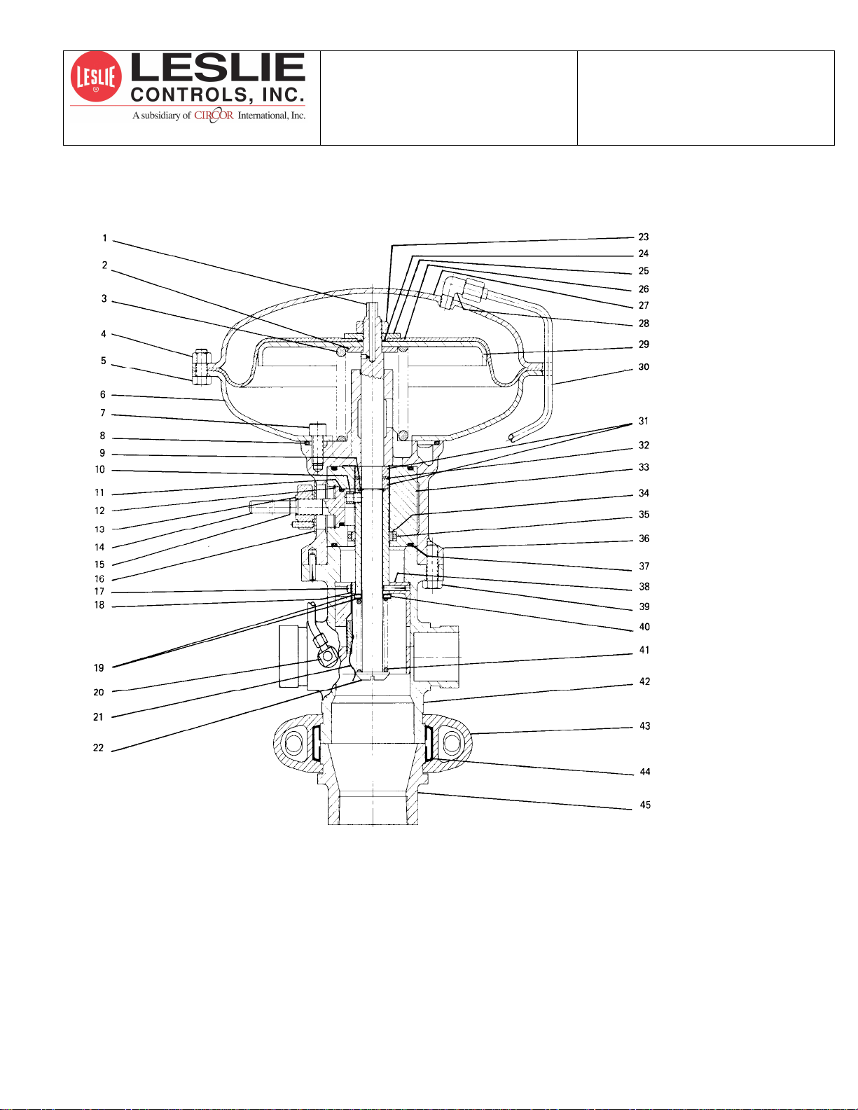
ring (24), shouldered washer (25), and jam nut
(23) over upper stem. Tighten jam nut after
positioning diaphragm holes over lower
diaphragm case (6) holes.
14. Install upper case (27) and position over
diaphragm holes. Make sure diaphragm lays flat
on flange and is not pinched or twisted. Fasten
bolts (5) and nuts (4) sequentially across from
each other until tight.
MAINTENANCE OF SYSTEM
COMPONENTS HEAT EXCHANGER
Check tightness of all casing bolts and nuts (80 to 90 ft-lb)
after unit has been in operation for a few hours and again
in twenty-four hours.
DISASSEMBLY
1. Disconnect water piping.
2. Remove all nuts around casing.
3. Remove casing from base plate.
4. Remove manifold nuts and lock rings. Coil
manifold and manifold gaskets.
ASSEMBLY
Clean all parts and replace any damaged parts. Use new
gaskets.
5. Install manifold gaskets between manifold collar
and base plate. Insert coil manifolds into base
plate.
6. Place lock rings over manifold ends with locks
fitted into slots. Install manifold nuts and tighten
securely. (A light coating of thread lubricant
should be used on manifold threads before
assembly of nuts.)
7. Place casing gasket on base plate and follow with
casing. Make sure recesses inside casing line up
with top of manifolds.
8. Install nuts and bolts and tighten evenly to assure
a tight leakproof seal.
9. Reinstall water piping.
10. Vent steam side of heater as described under
Section II - Start-up Procedure.
SECTION IV - TROUBLE SHOOTING
GUIDE
IMPORTANT! Study installation drawings and
CAREFULLY read the details concerning
installation of your Heater and Trapping System.
Following these recommendations will insure that
you obtain the maximum efficiency from your
CONSTANTEMP HEATER.
Recirculating Systems
PROBLEM: EXCESSIVE RISE IN WATER
TEMPERATURE OCCURRING DURING OR AFTER
PROLONGED PERIODS WHEN NO WATER IS BEING
USED FROM HEATER AND A RECIRCULATING
SYSTEM IS PROVIDED.
Too much water being re-circulated through
heater. Reduce water flow through heater by
throttling re-circulation stop valve to allow
enough time for water in piping system to
cool and assume new temperature setting. If
piping system is extensive and contains a
large volume of water, then the readjustment
of temperature can be speeded up by closing
steam supply stop valve to heat exchanger
and by then opening faucets etc. Preferably,
at end of loop until water temperature drops a
few degrees below the heaters adjusted water
temperature. Close off the re-circulation stop
valve and open the steam stop valve to
heater. With re-circulating pump in
operation, open re-circulation stop valve in
small increments while allowing adequate
time for water to be re-circulated throughout
piping before proceeding to next increment
of adjustment. Continue until desired re-
circulation water temperature is achieved.
1. IF A THREE-WAY THERMOSTATIC VALVE
IS USED, the port connected to the heaters cold
water supply MUST CLOSE to prevent excessive
flow of water back to heater. An excessive flow
will cause water temperature in piping to rise
above adjusted temperature setting of heater. If
port does not close, check for dirt or obstruction
between seating surfaces, or for damaged element
or seals.
2. CHECKING FOR FAULTY ELEMENT,
immerse unit in an agitated bath of hot water.
With a rise in water temperature of from 10 to
12¼F above rated operating range of element, the
port connected to heaters cold water supply pipe
should be replaced.
CHECK OPERATING RANGE OF ELEMENT
MAKING SURE RANGE IS THAT NEEDED
FOR YOUR SYSTEM.
1. NOTE: Operating range of Thermostatic Valve
should normally be from 10 to 15
0
F lower than
that of Heaters adjusted water operating
temperature. If heater is adjusted for 140
0
F hot
water and a 110
0
F 3-way valve is used, the re-

circulated water will assume a temperature of
110
0
F during prolonged periods when no water is
being used from heater. If a 180
0
F range unit is
used under the same conditions as above, the re-
circulated water temperature will rise to 180
0
F.
PROBLEM: EXCESSIVE DROP IN WATER
TEMPERATURE OCCURRING DURING OR AFTER
PROLONGED PERIODS WHEN NO WATER IS BEING
USED FROM HEATER AND RE-CIRCULATING
SYSTEM IS PROVIDED.
1. Check for correct inlet steam pressure to heat
exchanger.
2. No water being re-circulated back to heater.
Check re-circulating system for proper operation
of pump, re-circulation valves and controls.
Heat Exchanger and Blending Valve
PROBLEM: DROP IN CONTROLLED WATER
TEMPERATURE OCCURRING BEFORE RATED
CAPACITY (GPM) OF YOUR HEATER IS OBTAINED.
1. Check for correct inlet water operating pressure
and steam pressure to heater before and during
any operational test. LOW PRESSURE Heaters -
water pressure MUST be at least 5 psig ABOVE
maximum steam pressure used to operate Heater.
The MAXIMUM water pressure for all
Heaters is 150 psig.
NOTE: Seal plate (Part 45) must be tight seating to
prevent cold water from leaking into blended
water. This can cause an uncontrolled drop in
blended water adjusted temperature.
2. Check to make sure all steam strainers are clean
and that all traps are functioning efficiently. A
flooded or partly flooded heat exchanger will
cause little or no heat transfer. Excessive back
pressure in trap discharge piping system, or partly
clogged piping can restrict flow of condensate
from Heater and cause flooding. Dirty or partly
plugged strainer screens can also cause this
problem.
The above system must be operating efficiently
before any check for fouled coils can be made.
3. To check for fouled coils, remove pipe plugs from
blending valve base and cover, and install a gauge
in each connection. Temperature of water from
heat exchanger outlet piping should be
approximately 200 to 215
0
F when heater is being
operated within its rated capacity. (Temperature
may be checked by using a contact Pyrometer
held against a smooth filed section of exchanger
outlet piping.)
Steam pressures of from 2 to 15 psig
may be checked by using the
CAPACITY AND ADJUSTMENT
TABLE found in your Heater Manual to
determine GPM and water temperature
per your operating conditions.
TEST PROCEDURE: With traps functioning
efficiently, and with flow adjusted for 60% of heater rated
capacity (approx. 5 psig differential across blending valve
diaphragm), the heat exchanger outlet water temperature
drops below 200¼F and continues to drop as flow is
increased to heaters rated capacity in GPM, it indicates
that coils are fouled and should be cleaned or replaced. A
coil cleaning Adaptor Kit is available through your Leslie
Representative, along with instructions for its use. If
quality of water being used for Heater is poor, coils may
foul rapidly indicating that corrective water treatment may
be necessary.
PROBLEM: INSUFFICIENT STEAM TO HEAT
EXCHANGER.
1. See Paragraphs 1 and 2 above of trouble shooting
guide.
2. Check steam reducing valve operation, if one is
used with Heater.
3. PROBLEM: EXCESSIVE STEAM PRESSURE
TO HEAT EXCHANGER.
3. Check steam reducing valve if one is used or
steam source supplying heater.
PROBLEM: EXCESSIVE RISE IN WATER
TEMPERATURE ABOVE HEATERS
SETPOINT OCCURRING AT LOW FLOWS.
1. The above problem may occur if Heater
Controlled Temperature is overset due to:
a. fouled coils
b. drop in inlet water supply pressure
c. adjustment of controlled water
temperature while exceeding Heaters
rated capacity in GPM.
See Paragraphs 1 and 2 of the second problem for
further information.
PROBLEM: EXCESSIVE DROP IN WATER
TEMPERATURE BELOW HEATERS
ADJUSTED SETPOINT OCCURRING
DURING LOW FLOW.
1. See Paragraph 1 of Problem 2 above.
2. Inefficient trap operation or increase in trap
discharge drain piping back-pressure. See
Paragraph 2 of Problem 3.
3. Too little gain. Readjust gain setting as shown in
Paragraph 2 of Problem 3.

NOTE: A 3
0
F change in inlet water temperature to Heater
will produce a change in the Heaters adjusted
water temperature of 1
0
F.

F-340LDW

F-640LDW

F-940LDW

F-1240LDW
Re-Circulation System


INSTALLATION CHECK LIST
NOTE 1: PROVIDE ADEQUATE DRIP LEG AND TRAP TO KEP STEAM SUPPLY LINE FREE OF
CONDENSATE.
NOTE 2: INSTALL SAFETY VALVE AT THIS CONNECTION WHEN STEAM SUPPLY PRESSURE MAY
EXCEED 75 PSIG FOR DUCTILE IRON EXCHANGERS AND 150 PSIG FOR CAST STEEL
EXCHANGERS.
NOTE 3: INSTALL SMALL TRAP AND STRAINER TO DRAIN CONDENSATION DURING NO LOAD OR
STANDBY CONDITION.
NOTE 4: INSTALL THERMONETER SUPPLIED ON OUTLET HOT WATER LINE.
NOTE 5: INSTALL STOP VALVES ON STEAM CONDENSATE AND WATER INLET AND OUTLET
LINES.
NOTE 6: SEE TABLE BELOW FOR MAXIMUM ELEVATION OF CONDENSATE DISCHARGE.
MAXIMUM ELEVATION TABLE
INLET PRESSURE (PSIG) MAXIMUM ELEVATION OF CONDENSATE DISCHARGE
2-4 0 ft 0 cm
5-6 2 ft 61.0 cm
7-8 4 ft 121.9 cm
9-10 6 ft 182.9 cm

10-12 8 ft 243.8 cm
12-15 10 ft 304.0 cm
It is solely the responsibility of the system designer and the user to select products and materials suitable for their specific
application requirements and to ensure proper installation, operation and maintenance of these products. Assistance shall be
afforded with the selection of the materials based on the technical information supplied to Leslie Controls Inc.; however, the
system designer and user retain final responsibility. The designer should consider applicable Codes, material compatibility,
product ratings and application details in the selection and application. Improper selection, application or use of the products
described herein can cause personal injury or property damage. If the designer or user intends to use the product for an
application or use other than originally specified, he must reconfirm tat the selection is suitable for the new operating
conditions. Life expectancy for this product defaults to the warranty period of the sales contract.
This manual suits for next models
3
Table of contents
Popular Water Heater manuals by other brands

iDM
iDM HYGIENIK 2.0 installation instructions

Lochinvar
Lochinvar EJ 006 Series instruction manual

Ferroli
Ferroli SKY ECO F Instructions for use, installation and maintenance

Ariston Thermo
Ariston Thermo CD1 150 Operating Instructions and Guidelines for Authorised Technicians

Inalsa
Inalsa PSG1 instruction manual

Hubbell
Hubbell E Maintenance manual

Kenmore
Kenmore HydroSense 153.33443 owner's manual

clage
clage CFX-U Installing instructions for the professional

clage
clage GERMAN POOL GPIM7 operating instructions

Truma
Truma Ultrastore Rapid Operating and installation instructions

HSF
HSF EcoAdvance Compact Installation & user manual

blueclean
blueclean sp116 manual