circuitbenders drumBs PCB User manual
circuitbenders.co.uk drumBs build guide
Read the ENTIRE guide before starting work. This guide is for the standalone module
version of the drumBs board. The guide for the eurorack version can be found on the
circuitbenders site.
The circuitbenders.co.uk drumBs PCB is a tweaked version of the Syntom II, which was an analogue percussion
project first published nearly four decades ago in the April 1983 edition of the mighty Electronics & Music Maker
Magazine. ALL HAIL E&MM!
The drumBs PCB can create a wide range of basic analogue percussive sounds. Essentially these are the kind of
sounds that relate to modern drum machines like an Analog Rytm, Alpha Base or Tempest in the same way as a
Commodore 64 relates to the latest Apple Mac. On paper its shit in comparison, but it's cheap and fun, and
theres a certain dirty DIY magic to it! The drumBs synth section features both a VCO and a noise source, along
with a resonant noise filter and an auto roll function. It can be built in both a Eurorack or standalone format.
The standalone drumBs controls are:
SENSITIVITY: Optional trigger sensitivity if you're using a drum pad or piezo trigger of some sort.
DECAY: The decay of the percussion envelope.
BEND: The depth of percussion envelope applied to the pitch of the VCO and the filter cutoff of the noise source.
PITCH: The basic pitch of the VCO.
CUTOFF: The cutoff frequency for the noise filter.
REZ: The resonance of the noise filter.
PULSE: The level of an initial clicking attack at the start of the percussion sound .
MIX: The mix between the oscillator and the noise source.
ROLL: The repeat rate of the auto roll function.
VOLUME: Unsurprisingly is a volume control
TRIGGER INPUT: The trigger input accepts a standard +5v trigger pulse or gate to trigger the module.
AUTO ROLL SWITCH: The auto roll switch activates the auto roll function whenever the switch is closed. When
the auto roll function is activated the board will automatically retrigger itself at a rate set by the roll knob for as
long as the switch is closed. This can be very useful for creating unusually timed fills and rolls, although at its
highest trigger rate the roll function can sound like a constant VCO tone.
OUTPUT: You can probably work this one out for yourself.
PARTS LIST
PART NUMBER
PART VALUE
NOTES
D1, D2
1N4148
Diode
D3
1N5817
Polarity protection diode
R19
680R
All resistors standard 1/4 watt
carbon or metal film
R6, R7, R12, R13, R32, R33
R42
1K
R3, R9, R14, R18, R28, R35
4.7K
R8, R29, R37, R38
10K
R11, R21, R25
22K
R36
15K
R2, R5, R16, R20, R24, R26
R27, R34, R41
47K
R31
75K
R15, R30, R39, R43
100K
R1, R10, R22, R23
150K
R40
470K
R4, R17
2.2M
C16
100nF
Ceramic
C2, C3
1nF
Poly Film

C17
2.2nF
Poly Film
C1
10nF
Poly Film
C4
22nF
Poly Film
C5
47nF
Poly Film
C9, C15
100nF
Poly Film
C6, C10, C11, C12, C13
1uF
Electrolytic
C8
4.7uF
Electrolytic
C7
22uF
Electrolytic
C14
220uF
Electrolytic
IC1
TL072
Op Amp
IC2
LM324
Quad Op Amp
IC3
LM13700
OTA
IC4
LM13700
OTA
Q1
BC108B
Noise transistor*
J1
47K
Resistor to set the output level**
NOISE ADJ
100K trimmer
Headers
11 pin
2.54mm pin header optional***
Headers
11 pin
2.54mm pin header optional***
Headers
4 pin
2.54mm pin header optional***
Sensitivity
A47K
Potentiometer optional****
Decay
A500K
Potentiometer
Bend
B100K
Potentiometer
Pitch
A100K
Potentiometer
Filter Cutoff
A100K
Potentiometer
Resonance
A1M
Potentiometer
Pulse
A1M
Potentiometer
Mix
B100K
Potentiometer
Volume
B47K
Potentiometer
Roll
B500K
Potentiometer
Jack
6.35mm or 3.5mm
Trigger Input Jack
Jack
6.35mm or 3.5mm
Audio Output Jack
LED
5mm LED
Trigger LED
*The BC108B is commonly available in a metal can package and so that footprint is on the PCB. Other package
versions can also be used as long as the pinout is matched to the PCB markings.
**On the eurorack version this resistor at J1 is a wire jumper. Installing it on the standalone version takes the
output down to normal line level.
***You can use header pins or just wire the pots straight to the board
****The sensitivity pot is arguably useless if you are using standard +5v triggers, but has been included as an
option as it may serve some purpose if you are triggering the board using an old drum pad or piezo trigger. If you
leave this pot out then you must bridge the two solder pads it connects to at the board using a header jumper or
just shorting the pads with a piece of component leg.
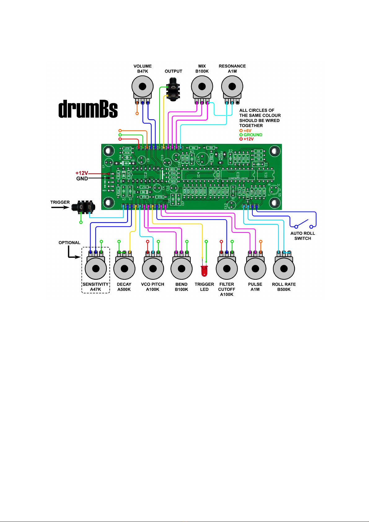
Pots, power and jacks wiring diagram.
All the small circles of the same colour shown on the diagram above should be wired together i.e. the red circles
are the 12v power rail connections, so pin one of the VCO Pitch pot and pin one of the Filter Cutoff pot should
both be wired to 12v at pin one of the header on the top left of the board as shown above . All the green circles
represent ground so they should all be wired together and then connected to pin 2 of the pin header on the top
left of the board, etc etc.
If you are mounting the pots on a panel it is a lot easier to wire all the 12v, 6v and ground connections from pot to
pot at the panel and then take one wire to the board, than it is to wire each connection to the board individually.
Don't forget the connections between two pot pins on the Decay and Roll Rate pots.
Power: The board should be powered using +12v at the solder pads for the eurorack type power connector on
the left. You only need to connect one of the +12v pads and one of the GND pads as shown on the diagram
above
Output Jack: The output jack can be wired to the main PCB using shielded audio cable. A ground pad has been
provided next to the output pad to solder the cable shield to.
Adjusting the noise trimmer: The noise trimmer allows you to adjust the frequency response of the noise filter
for the minimum amount of crackle or low end white noise. How you adjust it is a matter of personal taste, but
we've found its best to turn both the filter resonance and cutoff up to maximum. Then with the mix set fully
clockwise, the bend set to zero and the decay set to maximum, trigger the module and adjust the noise trimmer
until the crackle just disappears and you hear nothing but smooth noise.
Clicks: As with any analogue synth with a very fast attack envelope, you will sometimes experience clicks at the
start of the sound. This mainly only happens with low frequency oscillator sounds and is caused by the envelope
opening more or less instantly at a point where the VCO waveform is not crossing zero. This will vary in intensity
depending on where the VCO is in its cycle when the envelope opens. With this basic circuit it is unavoidable, but
it can be mitigated to some extent using the pulse control to make the click more regular and predictable. In
general use you may not even notice it.
Filter Cutoff / Noise Pitch: Due to an administrative fuck up the filter cutoff connection pin is labelled as 'Noise
Pitch' on the PCB. This is because thats what it's called on the Syntom II schematic, and some idiot forgot to
change it on the board. Rest assured those responsible have been severely punished!
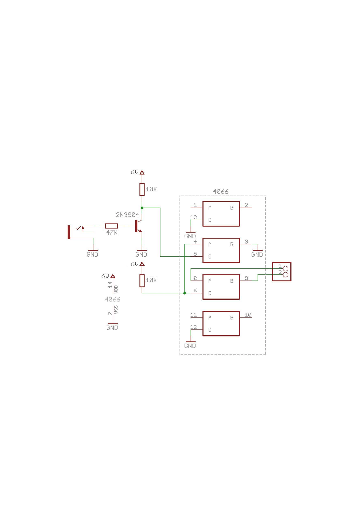
Auto Roll Switch: This can be any kind of switch or button that will close the contacts across the auto roll switch
pins. If you want to do it using an external gate signal like on the eurorack version you can build the circuit below
using a 4066 CMOS switch. The output should be wired across the auto roll switch pins. You can source the 6V
from the +6V pin on the main board.
Theres probably other ways of doing it, but for some reason we went with this version and have no recollection of
why! Maybe it just seemed like a good idea at the time.
Table of contents


