CircuitWerkes Sub-03a User manual

SubAudible
Tone Decoder
CircuitWerkes
Technical Manual
CircuitWerkes
3716 SW 3rd Place · Gainesville, FL 32607
(352) 335-6555 · Fax (352) 331-6999
http://ww.circuitwerkes.com
e-mail: [email protected]
c 1992-1997 CircuitWerkes AllRightsReserved. Allinformationcontainedwithinisproprietary.
NopartofthismanualmaybereproducedorcopiedwithouttheexpresswrittenconsentofCircuitWerkes.
Preliminary

Notes:

The CircuitWerkes Subaudible Tone Decoder
Description
TheCircuitWerkesSubaudibleToneDecoderprovidesareliableandaccuratesolutionfor
decodingsubaudibletonesfromsatellite,automation,orothersourcesofaudio. Theunithas dry relay
contactsandanLEDindicatorfor each of the standard three subaudiblesignals,25HZ,35Hzandthe
Combinationof25HZ and 35Hz. Alternately, the Sub-03a may beordered set for 50/75Hztones.
Theaudioinputcan accept balanced or unbalancedaudioatinput levels of -20dBm to +8dBm.
Theoutputisbalancedtransformerlessandiseasilycapableofdrivinga600ohmload. Subaudibletones
aretypicallyattenuatedby30dBat the audio output and it isshort-circuitprotected.
Installation & Setup
CONNECTIONS:
ConnectionstotheSubaudibleTonedecoder are fairly straight forward. Youraudiopassesthroughthe
decodervia the AudioIn and Audio Out jacks. The audio input jack has jumperJ-3 associated withit. J-3
providesaconvenient way to unground the input audio sleave if desired. Whentheinputisunbalanced,the
(-)inputlead must be tiedto ground. Relay outputs andthe power input arebroughtout to both barrier
stripsandaDb-9connector. Twoadditional barrierstrippositionsareforthe relay disable function. The
Sub-03amusthaveaconnection between these two positions for it to output contact closures. Finally, in
additiontotheterminal and Db-9 locations, thepowerinputmay be also be made toa2.5mmcoaxial (or
"barrel")connector. Allofthreeofthe power connectors are in parallel with eachother,so only onepower
sourceat a time can beconnected to the Sub-03a. See page 3 for connection details. Power is provided
bytheincluded"wall-wart."Optionally,the decoder cam be powered withanysupplyof18-24VoltsAC
orDCcapableofdelivering150mA.
Therelay outputs are dryN.O. contacts capable ofswitching loads upto 10 watts. Werecommend slave
relaysif youintendtoswitch heavyloadsorhighvoltages.
Important Note regarding program content...
Ifyoursubaudible tone decoder is connectedtoa source that deliversmorethan one program and oneor
moreoftheprogramsdelivereddoesnotcontainsubaudibletonesignalling youmayencounter (easily
resolved)problems. Any program thatdoesNOTcontainsubaudiblesignalling tones probably DOEShave
subaudiblecontent. Normal music/voice and background noisecaneasilysetoffyourdecoder'soutputs if
theaudioisnot(high pass)filtered. Programsthatdo containsubaudiblesignallingtoneswill alwaysbe
prefilteredattheiroriginationpoint beforesubaudibletonesare injected,thuskeepingthenaturallow
frequencycontent ofnormalvoiceand noisefromfalsetrippingdecoders downtheline.
Agoodexamplewouldbean SCPC satellite receiver that you useforacoupleofdifferent network feeds.
Oneof the networks uses subaudibletonesignallingforstartinglocalbreaks,the other uses DTMF Tones.
ThenetworkthatusesDTMFtonesprobablydoesnotfilteroutthesubaudibleportionoftheirprogram
audio. Ifyou have alimitednumberofinputson your console orautomationsystem,youmaynot wish to
takeuptwoinputswithaudiofromonesource. FortunatelytheCircuitWerkes Subaudible ToneDecoder
featuresa disable input. Connecting this linetothedecoder'sgroundwillenablethe relays. Youmay
connectthis lineandthedecoder'sground to atimedautomationoutputthat willsinktogroundonly during
theprogram whose tones you wanttouse. Anyothertime,theautomationwould unsink the disable input
and the tones will not cause relay closures. If you do not wish to use the disable function, a wire
jumper must be installed between the two screw terminals to enable the decoder.

Audio
Input
Level
Set Audio
Input
connector
J-3
Input
Sleeve
ground
User Interface
Connectors Power Input
And LED
Audio
InClip
LED Audio
Output
Level
Set
Output
Clip
LED
Audio
Out
Connector
J-1
Input Pad
J-2
Input
Gain
Select AudioInputJumpersettings:
Input level = +8dBm: J1 & J2 = ON
Input level = +0dBm: J1 = ON/ J2= OFF
Inputlevel = -10dBm: J1& J2= OFF
Sub-03aConnector&ControlsLayout(TopView)
SETTINGLEVELS:
TheSub-03acanacceptawidevarietyofinputlevelsanditsimprovedoutputdrivercansupplypeaklevels
ofupto +18dBm into a 600Ohmload. There are 2 jumpersassociatedwith the input audio levels. Ifyour
audioinput is at+8 or more, both J1 and J2 shouldbe on. If yourinput is at 0dBm, only J1 needs tobe set.
Ifthe audio inputlevelis-10dBmorless, then both jumpersshouldbeoff.Whicheverjumper setting you
choose shouldallowthemaximumamountofinputaudioWITHOUTlightingtheinputclippingLED. The
Sub-03ahas a maximumdynamicrangeofabout90dB. By selecting the highestinputlevelthatdoesnot
causeclipping oftheinputstage, youaregetingthemaximum signaltonoiseratio fromtheSub-03a.Since
satelliteprogrammingispre-limited,youmaybeabletousemore aggressiveinputjumper settingsto
maximizeaudiothroughput. Thisis fineaslongastheinputclippingLEDstaysoff. Aftersettingtheinput
jumpers,adjust the input level controlpot onprogrammaterialuntiltheInputPresence LED is lit 50-70%
ofthetime. Thisisthecorrectlevelrangeforthetone detectors to work. Finally,adjust the output level
controlforthelevelthatyou want. This control is variable from 0 toabout+18dBm. Besurethatthe
outputclipping indicatordoesnotlight, oryouwillhavea distortedoutput.
Audio
Present
LED
Jumper

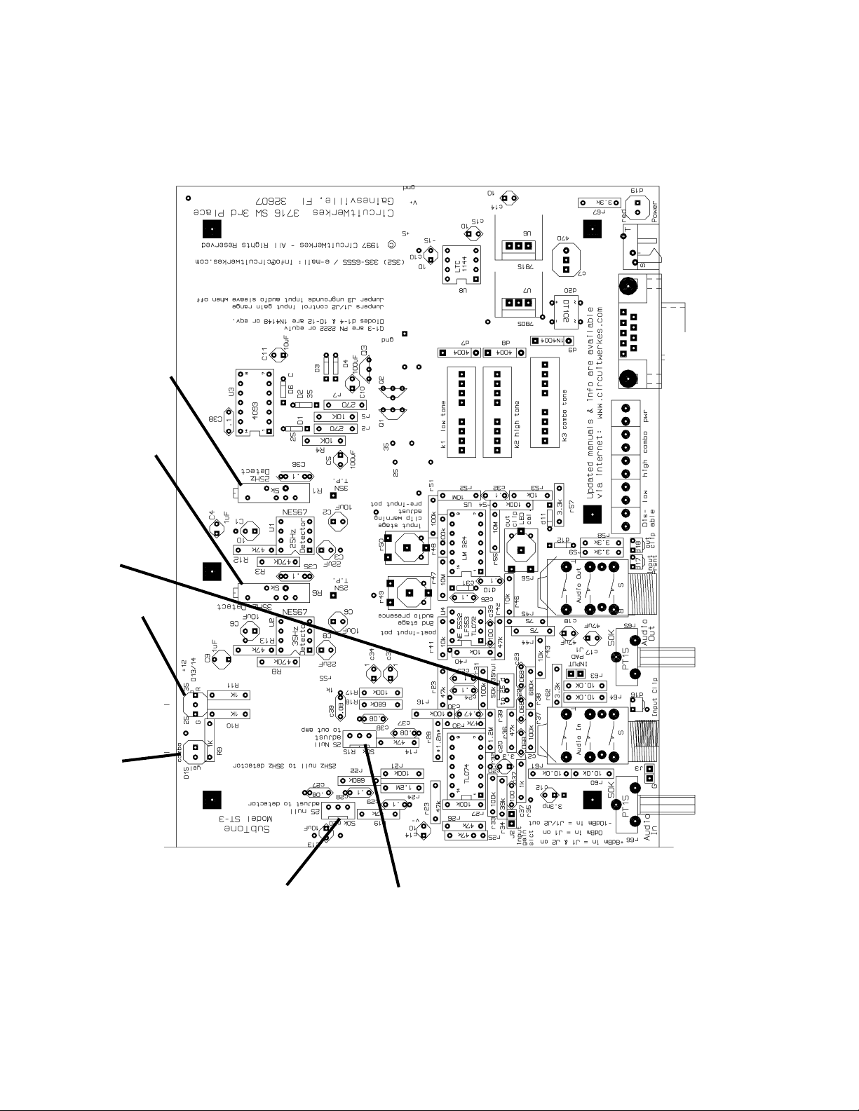
SUB-3 PC Board Layout
Main25Hz
Nulladjust(to
detector)
Secondary
25HzNull
adjust(to
audiooutput)
35Hz Null
adjust
25 Hz Detect
Calibration
35 Hz Detect
Claibration
Low(red)
&High
(green)Tone
Detection
LED
Combo
Tone
Detection
LED
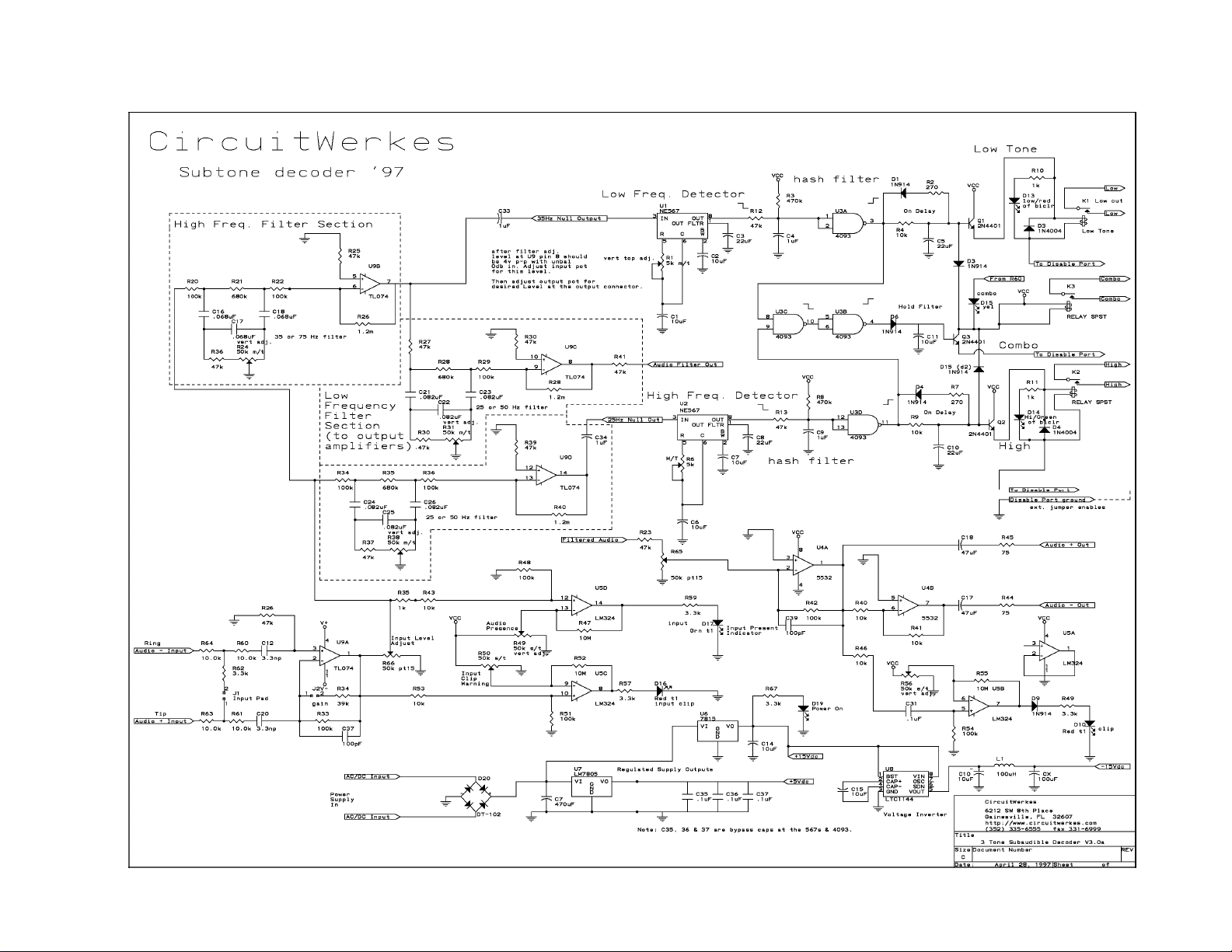
Sub-3 Subaudible Tone Decoder Schematic

Theory of Operation
IncomingaudioisbufferedandlevelcontrolledbyU9aanditsassociatedcomponents. Threenodesare
fedby thisfirstbuffersection,the audioinputclippingindicator,theinputaudiopresenceindicator(U6b),
the35Hznotchsection(U9b)and the main 25Hz notch section, U9d.
Theaudioinputclippingand presenceindicatorsarebasically identicalexceptthattheclippingindicatoris
drivendirectly from thefirstbuffer'soutputandis set to aleveljustbelowthepoint where theinputbuffer
overloads. Theaudiopresentindicatorisfedfromjustaftertheinputgaincontrolpotandiscomprisedof
opampU6b (operated as a comparator),reference-set pot R53, a yellow LED and associated
components. Whentheaudiolevelexceedsthe preset comparator reference level, the comparatorchanges
statesand illuminatedtheLED. Thereferencelevel pot issettoilluminatethe LEDwhendetection
amplitudeisideal.
The35Hz notchsectionisamodified twin-tee circuit,theexactcenterfrequency ofwhichissetby multiturn
potR24. BufferU9b feedsthe 25 Hzdetector section and a secondary 25Hz notch filter, U9c,(of the
samedesign)whichinturnfeedsthebalancedoutputampscomprisedofU5anditsassociated
components. Anothercomparator-LED circuit hangs off theendoftheoutputampandis set to illuminate
whentheaudiooutputlevel approachesclipping.
Themain25Hzfiltersection feedsthe35Hzdetectorsectionwhilethe35Hzfilterfeedthe25Hzdetector.
Itisnecessarytoremovethe opposite frequency tones from the audiofeedingeachdetector.
Theoutputs ofthetwodetectorsections feed throughhashfilters(toeliminate anyextraneousfalsing). The
hashfiltersaresimpleRCconstantsonSchmitttriggerinputsofU3a(25Hzdetector)andU3d(35Hz
detector). Theoutputsof the hash filtersfeed an AND gate(comprised of U3c andU3b)directly and the
relaydrivercircuitsfortheirrespectiverelaysthroughanRCdelayfilter. Ifbothtonesaredetected
simultaneously,the ANDgatecircuitfiresthecombotone relay and defeats the relaydriversofthe
individualtoneoutputs. If only a single tone is detected, its relay output folowsafterabriefdelay.

Alignment
Levels.
Audiolevelscanbeadjustedwiththefrontpanelaudiopots(InputandOutput). StartwiththeInputlevels
andfeed theunitwithnormal programaudio. Adjusttheinputuntil theinputaudiopresence LEDflashes
withabout 50-70% dutycyclewiththeincomingaudio; it can flashmoreiftheaudiois densely processed.
Outputaudioshould be adjusted for desirable levels into your console orautomation. Ifthered"OutClip"
LEDisilluminatingatall,youaregettingwithin4dBofclippingonpeaks. IfthissameLEDisnotlighting,
butyour audio out is distorted,youareprobablydrivingtheinputtoo hot. Check for a flashing"InputClip"
LEDand set theinputgainjumpersforthe maximum gain thatdoesNOTcausetheinput clip LEDtoflash.
Filters and Detectors.
Alladjustmentsto the decoder assume25 and 35 Hzsignal decodeing. The process forsetting50 and 75
Hzdecodingisidentical,except,ofcourseforthefrequencies. 50Hzis substituted for 25Hz and 75Hz subs
for35Hz. Thefilter sections and detectors aretunedat the factory withstandardreference tones and
shouldnotneedfurtheradjustmentbytheuser. However, if the need unexpectedly arises to tune these
circuitsectionsyou will need a scope or analog audio level meterthathasgooddisplaycharacteristicsat
lowaudiofrequencies,asignalgeneratororknownaccurate25Hzand 35Hz signal source, and an accurate
frequencycounter ifyoursignalsourceis a continuouslyadjustabledevice(mostare). The frequency
countercanbelefthung acrossthesignalsource forfinetuningthefrequencyofthe signalsbeingfedduring
thealignmentprocess. Theaudio level of the tonesourceshouldbe between -10 and +8 dBm,depending
uponjumpersettings. Ifthesignalisunbalanced,besuretotieringandsleeveontheinputconnectortothe
unbalancedsource's shield.
ToTunethe filter sectionssetthegeneratororsignal source fortheoperatingfrequencyofthe filter being
tunedand adjusttheassociatedmultiturn potforminimumaudio(the nullpoint)atthe testpointforthe filter
youare adjusting. The two maintone test points aresquare pads onthe PC Board nearvariable resistors
r1and r6. They are labelled 25N T.P. and 35NT.P. AdjustR20 to null 25Hz. Adjust R39 to null 35Hz
Secondary25Hz - adjust R15- test point isthe main audiooutput.
Thedetectors shouldnotbealignedunless the filtersectionshavebeenaligned first.
Thedetectoralignmentprocessisthe same for both detectors. First set thesignalsourcefortheoperating
frequencyof the detector you willbetuning,thenfindtheturn-onpoint of the detector ineachdirectionof
rotationofthemultiturndetector'salignmentpot. Setthepotforhalfwaybetweentheetwopoints.
R1isthe 25Hz detector adjustment; R6isthe 35Hz detector adjustment. To find thecenter of the
detector'srange,reducetheinputgainuntilthedetectorjustbarely operates. Very slowly adjust the
multiturnpotaboutaturnin each direction noting where the centeroftheturnonrange is. Set the pot to the
centeroftherangeandyou're done. Note that there is hysteresis intheindividualdetection outputsto
allowthecombotonelogica chance to operate. That means that youmustadjustthedetectioncircuit
extremelyslowlyinordertogetanaccurateideaofthe center range.

REPAIR OR SERVICE INFORMATION
Intheeventoftheneedforserviceor repair, call CircuitWerkesat(352)335-6555foraReturn
MerchandiseAuthorizationnumber(RMA). Thencarefullypackagetheunitalongwithanote
oftheproblem andsend it to theaddress below. Clearly indicatethe RMAnumberon the
outsideofthebox. WecannotacceptreturnswithoutanRMA. Besuretoincludeyour
address(nota PO box),telephonenumberandbesttimetocall.
CircuitWerkes
ATTN: CUSTOMER SERVICE DEPT.
3716 SW 3rd Place
GAINESVILLE, FL 32607
CircuitWerkesLimitedWarranty
This product is warranted against defects for two years from date of
purchasefromCircuitWerkesandCircuitWerkesauthorizeddistributors.
Within this period, we will repair it without charge for parts and labor.
Proof of purchase-date required. Warranty does not cover
transportation costs, or a product subjected to misuse, accidental
damage, alteration (except as authorized by CircuitWerkes),
improper installation, or consequential damages.
Exceptasprovidedherein,CircuitWerkesmakesnowarranties,express
or implied, including warranties of merchantability and fitness for a
particular purpose. Some states do not permit limitation or exclusion
of implied warranties; therefore, the aforesaid limitation(s) or
exclusion(s) may not apply to the purchaser. This warranty gives you
specificlegalrights andyoumayalso haveotherrightswhichvaryfrom
state to state.
Note: Manualsarefrequentlyupdatedinordertoimprovethem. Thelatestversionofthismanualis
availableonline attheCircuitWerkesinternetwebsite. Theaddress is: http://www.circuitwerkes.com/
E-mailmaybesentto [email protected].
Table of contents
Other CircuitWerkes Media Converter manuals


