CircuitWerkes DTMF-16d User manual

1
Technical Manual
CircuitWerkes
2805 NW 6th Street · Gainesville, FL 32609
(352) 335-6555 · Fax (352) 380-0230
http://www.circuitwerkes.com
Touchtone®Decoder
DTMF-16d
© 1992-2010 CircuitWerkes AllRightsReserved. Allinformationcontainedwithinisproprietary.
NopartofthismanualmaybereproducedorcopiedwithouttheexpresswrittenconsentofCircuitWerkes.
Touchtone
®
is a registered trademark of AT&T. Manual updated 10-29-2010
CircuitWerkes

2

3
Description
The CircuitWerkes DTMF-16 is an integrated Touch Tone detector and sixteen output decoder, offering a
combination of dry relay and optoisolated Darlington outputs for each of the sixteen standard DTMF tones. All
outputs are fully programmable and can respond to single DTMF tones or can respond to sequences up to 6 digits
in length. Outputs are individually set and can be momentary, latching or interlocked (radio button). Each output
can be configured for leading or trailing edge operation. Two of the relay outputs are DPDT (dual form C) and
two are SPST (Form A). Seperate emitters and collectors are available for each of the twelve remaining
optocoupled outputs. The optically isolated, open collector, Darlington , outputs provide 5000 volts of isolation
and are capable of sinking up to 150mA continuously (emitter-collector voltage should not exceed 30 volts).
These outputs along with ground are available at the unit's D-25 pin connector. When interfacing the DTMF-16's
outputs to low Voltage dc lines such as computer inputs, etc the optocouplers provide greater isolation and do
not contain mechanical parts to wear out as with relays. It is not normally necessary or suggested to use external
relays unless you are planning to switch AC Voltages or audio signals. Correct polarity must be observed for
the optocouplers to work. Since any output (relay or optocoupled) can respond to any tone, the combination of
optocouplers and relays allows most users to interface to everything without use of external hardware.
The D25 connector also contains serial data and can be used to program your DTMF-16. The connection settings
are 2400b, N81, with no flow control or hardware handshaking. Any common terminal program can be connected
to the DTMF-16. Pressing the esc key brings up the programming menu where you can setup all of the
configurable parameters of your DTMF-16.
Installation & Operation
Setup
The DTMF-16 comes from the factory ready to use, just hook up an audio source to the Audio In (AudIn + and
-), connect your equipment to the screw terminasl for the relays or to the D25 for the remainder of the outputs, plug
in the power supply and it's ready.
Jumper JP2 (STB-DLY) delays detection of the DTMF tones for a fraction of a second. The delay prevents the
decoder from detecting transient audio passages containing valid DTMF frequencies from being decoded. This
anti-falsing delay provides reliable detection of single DTMF tones that last for at least 1/2 second. Several
satellite news/sports networks use long DTMF tones for signalling affiliate breaks and cues.
Mounting
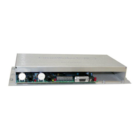
The basic DTMF-16 can be either desk or wall mounted. Keyhole cutouts on the ears of the enclosure are
provided for wall mounting. Two optional rack mounts, the RM-01 and RM-02 are also available for those who
would like to mount one or two DTMF-16s in a 19 inch rack cabinet.
Basic Operation
The DTMF-16 requires no operator intervention. It monitors an audio source until a valid DTMF tone or combination
sequence occurs, then energizes the tone's corresponding relay or optocoupler.
Connections
The power connection is made via 2.1 mm coaxial jack and will accept from 8 to 18 Vac. A power supply is
provided with each DTMF-16; however, if you wish to supply your own, it must be able to provide at least 200ma.

4
The DTMF-16's audio connection is balanced, bridging and is made via the screw terminals marked AudIn (+)
and (-) When connecting to an unbalanced feed, use (+) and ground with (-) tied to ground as well.
Audio input level should be between 0.1 and 2 volts peak to peak
Connecting the DTMF-16 to other equipment:
The DTMF-16 has two types of outputs, relays and optocouplers. Relays are dry switches that can be used to
interface to anything within the relay's mechanical operating parameters including audio, digital logicand general
purpose controls. The relays on the DTMF-16 should not be used for handling dangerous Voltagesbecause they
are not rated for that and it is extremely unsafe to connect any such Voltage to the DTMF-16 due to the possibility
of accidental electrocution. Just don't do it. Ever.
Care & Feeding
Generally, the DTMF-16 may be placed anywhere other electrical equipment is in operation. As
always, it is best to avoid extreme temperatures, immersion, or high impacts.
If you wish to clean the outside of the DTMF-16, use a damp cloth soaked in a mild soap and water solution.
Detergents, alcohol, or solvents may remove the screen printing or mar the case.
Audio Input
Balanced
Relay 1 Outputs. DPDT
Can be used to switch audio or for
control as desired.
Com connects to NO when powered
on a or to NC when unpowered.
Relay 2 Outputs. DPDT
Can be used to switch audio or for
control as desired.
Com connects to NO when powered
on a or to NC when unpowered.
Audio Output when equipped
with optional Silencer
K3 and K4 are
SPST dry relays D25 connector.
See below
Power Input AC or
DC 12-18V 250mA.
TheDTMF-16Dconnectorpinout
Thisconnectorcontainstheemitter(E)
andcollector (C) of eachofthe remaining
optoisolatedoutputs. Theseoutputs
function like low power relays, but they
can only be used for DC circuits & are
polaritysensitive.
Serial Data is present on pins 2 and 3 with
ground on pin 1 and 7. Jumper JP4 and
JP5 set the type of cable from standard to
nullmodem.
The DTMF Valid line is for factory test
purposesonly.

5
Programming
RS232 Configuration: 2400 Baud, 8 data bits, No Parity, 1 Stop Bit, No Flow Control.
There is a hardware setting on the board that allows you to choose the type of cable that you will be using. This is
done by changing jumpers JP4 and JP5. You may select either null-modem or normal serial cable. The default
cable setting for the DTMF-16 is "normal", but many of the commercial D-9 to D-25 cables are setup for null modem
inorder to connectto external modems. Ifyou arenot making yourown cable, youshould probablytry the "Null_Mdm"
position.
The DTMF-16 user defined settings consist of a global configuration setting and a 16-channel table, called
Prog. Table, that will hold all the custom trigger codes and trigger settings programmed by the user. For
each channel, the customer can program 3 parameters: Trigger Edge Mode, Latching Mode, and one or two
DTMF Trigger Codes(DTC).
Channel Settings:
•Trigger Edge Mode- Determines whether the channel will trigger on the Leading or Falling
Edge of the last digit of the DTC received on the audio input
•Latching Mode- Determines how the channel output will react once the DTC is received.
•Momentary- Output will remain High for the duration of the last digit of the DTC.
•Latching-Output will remain High until the corresponding off code DTC is received.
•Interlocked Latching-Output will be pulled High and all other outputs in the interlocked group
will be pulled low. Output will remain high until the global interlocked off code DTC is
received.
•Fixed Duration-Output will remain High only for the preconfigured global Fixed Duration time
(this is set in the config routine).
•DTMF Trigger Codes(DTC)- Each channel setting has a maximum of two DTCs that can act to turn the
triggered channel on or off, depending on the Latching Mode. The first code is always an ON code.
For the Momentary and Fixed Duration modes, the second code is simply a different ON code and
either will pull the output High. For the Latching mode, the second code is the OFF code and the
output will remain high until this is received. For the Interlocked mode, the second code is the global
interlocked OFF code. This code is shared by all channels in the interlocked group and only
affects those channels.
Table of contents
Other CircuitWerkes Media Converter manuals
Popular Media Converter manuals by other brands

H&B
H&B TX-100 Installation and instruction manual

Bolin Technology
Bolin Technology D Series user manual

IFM Electronic
IFM Electronic Efector 400 RN30 Series Device manual

GRASS VALLEY
GRASS VALLEY KUDOSPRO ULC2000 user manual

Linear Technology
Linear Technology DC1523A Demo Manual

Lika
Lika ROTAPULS I28 Series quick start guide

Weidmuller
Weidmuller IE-MC-VL Series Hardware installation guide

Optical Systems Design
Optical Systems Design OSD2139 Series Operator's manual

Tema Telecomunicazioni
Tema Telecomunicazioni AD615/S product manual

KTI Networks
KTI Networks KGC-352 Series installation guide

Gira
Gira 0588 Series operating instructions

Lika
Lika SFA-5000-FD user guide


