CircuitWerkes Silencer II User manual

DTMF Mute
Model Silencer II
CircuitWerkes
Technical Manual
CircuitWerkes
3716 SW 3rd Place · Gainesville, FL 32607
(352) 335-6555 · Fax (352) 380-0230
http://ww.circuitwerkes.com
e-mail:[email protected]
c 1995-1999 CircuitWerkes All Rights Reserved. All information contained within is proprietary.
NopartofthismanualmaybereproducedorcopiedwithouttheexpresswrittenconsentofCircuitWerkes.
1

Silencer II Technical Manual
The Silencer II is a stand-alone DTMF muting device designed to pass high quality audio (from
whatever source is feeding the device) without undesired Touch-Tones.
Audio containing DTMF tones is fed into the Silencer II's input jack and audio minus the DTMF
tones is fed from the output jack. The Silencer II contains a DTMF decoder and an audio delay.
Anything the DTMF decoder detects as a vaild DTMF tone gets muted from the Silencer's audio
output. An integral 50 millisecond audio delay in line with the audio output ensures that the muting
action occurs just before the tone makes it to the balanced audio output.
Getting Started Quickly
Both input and output jacks are active balanced. When driving unbalanced loads, the negative (ring)
lead should be left floating. The unit is set for unity gain and optimized for 0dBm input. Simply
connect input, output and power and the Silencer II will work.
The pages that follow contain a parts layout for the Silencer II board and a schematic and short theory of
operation. If you experience trouble with your Silencer II or need assistance, please feel free to call us at (352)
Audio
Input
Jack
Input
Gain
Control
Audio
Output
Jack
Output
Level
Control
External Mute
Control
(see theory of
operation)
2
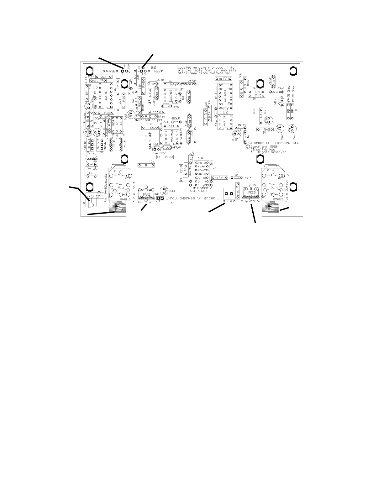
The Silencer II PC Board Layout
The only user adjustments on the silencer board are input and output level adjust pots. The input
level adjust can be optimized for best S/N ratio when dealing with varying input levels such as appli-
cations where the input audio peaks at -10dBm (audio from an FCC registered telephone coupler like
our AC). To adjust the level, send in a tone at whatever level you will be using. Turn the output level
control down so that the output is at -10dBm. If, during input level setting, the output rises above
0dBm, decrease the output level control as needed. Increase the input level until clipping is observed
or heard, while making sure that the output level does not rise above 0dBm. Once clipping is
observed, decrease the input control so that the output level falls by 15dB. Then set the output
control to the desired level, keeping in mind that 10 to 15dB of headroom should be maintained.
Theory of Operation:
Incoming audio is buffered by U7a and routed to U4, a MAX 7403, switched capacitor filter
through the input level contrtol pot. This pot is factory set for 0dBm inputs. The filter chip is config-
ured to limit generation of aliasing noise in the next stage. The conditioned audio is fed to Analog
delay chip U3. U2 generates the appropriate (approximately 21kHz) clock for U2's opeartion as a
50msec delay line. The delayed output has a 21kHz clock component that is virtually eliminated by
switched capacitor lowpass filter U5. Before the audio gets to U5 it connects in an AC-coupled-only
node to the mute circuit made up of q1 and its associated components. DTMF detection is provided
by an MC145436 DTMF decoder IC. When a valid DTMF-tone is detected, it activates the mute
circuit on the Silencer. The muted circuit simply shunts the audio to ground for the duration of the
incoming tone. The filtered, delayed audio from the output of U4's filter is amplified by opamp U7.
The Opamp is set up to provide a balanced transformerless output. External control of the mute
function is provided at the screw terminal M.C. Grounding this terminal prevents the mute from
operating while supplying 5V at the terminal mutes the output regardless of if a tone is detected.
DV LED (lights when DTMF detected)
Power LED
Audio Input -
Balanced, T-R-S.
For unbalanced use,
tie ring (-) to sleave.
Mute Control.
+5V mutes.
Grounding
disables mute
Output
level
control
Audio Output jack -
Balanced, T-R-S.
Do not ground
unused output.
Input gain control -
Set for beginning
distortion and then
reduce 10-15 dB
Power -
14 to 20V
ac or dc.
3

4
Table of contents


