CircuitWerkes CW Broadcast ES Series Guide

CW Broadcast
111 N. Vista Rd, Ste 3E
Spokane Valley, WA 99212
Phone—(509) 290-6652 / (888) 889-2958
World Wide Web—http://www.cwbroadcast.com
CircuitWerkes reserves the right to revise and change any and
all information included in this document.
ES Series
Operating Manual
and User Guide
Version 2.0— Aug 2022
TM
TM
CW Broadcast
ES Series Operating Manual and User Guide
CW Broadcast


Copyright © 2022 CircuitWerkes, Inc.
ALL RIGHTS RESERVED. No part of this publication may be reproduced, transmitted,
transcribed, stored in a retrieval system, or translated into any language in any form by any
means for any purpose other than the purchaser's personal use without the permission of CircuitWerkes, Inc.
The information in this publication has been checked and is believed to be accurate. However,
CircuitWerkes, Inc. assumes no responsibility for inaccuracies. We retain the right to make changes to this
publication at any time without prior notice. CircuitWerkes, Inc. does not assume any liability arising from the
application or use of this publication or the product(s) described herein.
RESTRICTED RIGHTS LEGEND: Use, duplication, or disclosure by the United States
Government is subject to the restrictions set forth in DFARS 252.227-7013 (c)(l)(ii) and FAR
52.227-19.
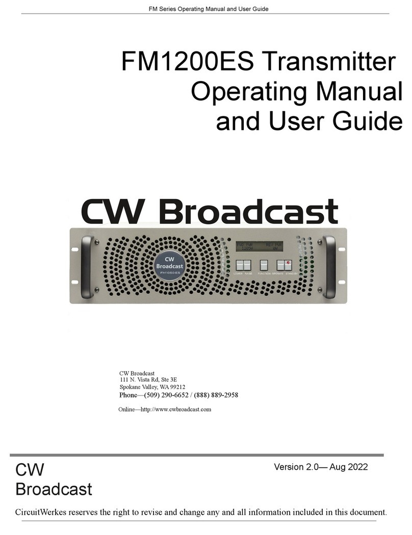
This manual is for these CW Broadcast transmitters:
FM300ES, FM500ES, and FM1050ES
Operating Voltage Requirements:
FM300ES and FM500ES are Single Phase 110VAC Transmitters
***The PTEK FM1050ES is a Dual Phase 110VAC device, more commonly referred to as
220VAC***
Warranty Service:
ES Series transmitters are warranted for a period of 42 months from date of purchase.
During the warranty period we will repair or replace the transmitter, at our sole discretion.
No refunds will be issued after 90 days. Contact customer service to obtain an RMA for your product.
This warranty does not cover acts of God such as lightning. Damage caused by misuse or shipping
is excluded from the warranty. CW Broadcast will not warranty the product due to misuse, accident,
neglect, and improper installation or operation, or abuse such as immersion in water or direct exposure to the
natural elements.
The Limited Warranty covers parts and labor to the original purchaser as outlined on purchase invoice for use in
the United States of America. Customer is responsible for shipping to us. We will prepay ground shipping back to
the customer.
---These transmitters are not recommended for use as a replacement IPA—
Proper installation includes A/C line surge suppression, lightning protection and proper grounding of
the entire transmitter, and any other recommendations designated in this Operating Manual.
CW Broadcast
Customer Service Manager
111 N Vista Rd, Suite 3E
Spokane Valley, WA 99212
(509) 290-6652 / (888) 889-2958

Safety Instructions
To maximize user safety and ensure corr ect device operation, all instructions con-
tained in this section should be read carefully.
Before Applying Power
Verify that the line voltage is 115 to 230 VAC, single phase.
Ground the Exciter
Caution: It is important that the user observeall warnings and instructions that
are on the device and contained in this manual.
Warning: DO NOT OPERATE IN AN EXPLOSIVE ATMOSPHERE
Operation of the transmitter in the presen ce of flammable gass es or fumes can
endanger persons proximate to the site of operation.
Caution: NO NOT REMOVE THE TRANSMITTER’S COVER
Removal of the exciter cover will invalidate the Warranty.
Component replacement and internal adjustments must be
made only by CW Broadcast qualified service personnel.
To minimize shock hazard, the exciter chassis must be connected to an electrical
ground, the exciter must be connected to the AC power mains through a three-
conductor power cable, with the third wire connected to an electrical ground (safety
ground) at the power outlet. Any interr uption of the protective (grounding)
conductor or disconnection of the protective earth terminal will cause a potential
shock hazard that could result in personal injury. If the exciter is to be energized by
any other source be certain that the chassis is connected to a separate safety ground.

Fuses
Only fuses with the same required current, voltage rating, and specified type (nor-
mal blow, time delay, etc.) should be use d. Do not use repaired fuses or short-cir-
cuited fuseholders. To do so could cause a shock or fire hazard.
Output Connector
Electrostatic Discharge (ESD)
A sudden discharge of electrostatic electric ity can destroy static -sensitive devices
or micro-circuitry. Proper packaging and grounding t echniques are necessary pre-
cautions to prevent damage. Always take industry-standard precautions.
Grounding Methods
Guard against electrostatic damage at workstations by following these steps:
1. Cover workstations with approved anti-static material. Provide a wrist strap connect-
ed to a work surface and properly grounded tools and equipment.
2. Use anti-static mats, heel straps, or air ionizers to give added protection.
3. Handle electrostatic-sensitive components, boards, and assemblies by the case or the
PCB edge.
4. Avoid contact with pins, leads, or circuitry.
5. Turn off power and input si gnals before inserting and removing connectors or test
equipment.
6. Keep the work area free of non-conductive materials such as ordinary plastic assem-
bly aids and Styrofoam.
7. Use field service tools, such as cutters, screwdrivers, and vacuums that are conduc-
tive.
Warning: The type-N output connector carries dangerously high RF voltages
that present shock and burn hazards. Never operate the transmitter with-
out properly terminating the output connector in either an adequately rated load
or antenna.

General Safety Rules
•The device must be used in acco rdance with the instructions for use.
•Electrical installations in the room must co rrespond to the requirements of respective regu-
lations.
•Take care that there are no cabl es, particularly mains cables, in areas where persons can trip
over them.
•Do not use a mains connection in sockets shar ed by a number of other power consumers. Do
not use an extension cable.
•Only use the mains cable supplied.
•The unit is completely disconnected from the pow er source only when the power cord is dis-
connected from the power source. Therefore the power cord and its connectors must always
remain easily accessible.
•Do not set up the device in the proximity of h eat sources or in a da mp location. Make sure
the device has adequate ventilation.
•All plugs on the connection cables must be screwed or locked to the chassis housing.
•The device is designed to be used in horizontal position only.
•The device is no longer safe to operate when the device has visible damage or the device no
longer functions.
•In case of system malfunction or visible damage to the FM 500ES, the device must be shut
down and secured against unintentional operation.
•Repairs may only be carried out by a person authorized by CircuitWerkes, Inc..
•If extensions are made to the transmitter, the le gal stipulations and the device specifications
must be observed.
•The transmitter must be switched off and the line cord disconnected from the AC source
when removing the top cover.

Table of Contents
Limited Warranty .................................................................................................................iii
Warranty Service ..................................................................................................................iii
Safety Instructions ..................................................................................................................iv
Preface ...................................................................................................................................xiii
Website Information ...........................................................................................................xiv
Your Comments are Welcome ............................................................................................xiv
Notes, Cautions, Warnings, and Sidebars ...........................................................................xv
1. Overview and Specifications
..................................................................................…....1-1
1.1 Overview
.........................................................................................................….....1-1
1.2 Specifications
..................................................................................................….....1-4
1.2.1 General ............................................................................…….....................1-4
1.2.2 Electrical ...............................................................................................…....1-5
1.2.2.1 System Power ........................................................................……....1-5
1.2.3 Environmental ...................................................................................…......1-6
1.2.3.1 Shock .................................................................….......…......…......1-6
1.2.3.2 Electrostatic Discharge ...............................................… ...........1-6
1.2.3.3 Noise Level ....................................................................….............1-6
1.3 Packaging and Shipping
..… .................................................................….................1-7
1.3.1 Rack-Mount Slides (Optional
) .....................................…........…................1-7
2. Installation
......................................................................................................….............2-1
2.1 Installation Procedures
.............................................................................…............2-1
2.2 Removing the Protective Top Cover
........................................................….….........2-2
2.3 Removing a Power Supply .....................................................................…..….........2-2
2.4 Changing the Fuse ................................................................................……..........2-5
2.5 Cleaning the Air Filter ................................................
..................................….......2-6

2.6Rack Mounts ..........................................................................................................2-7
2.6.1Mounting Brackets .....................................................................................2-7
2.6.2Rack-Mount Slides (Optional) ...................................................................2-8
3.Operation .......................................................................................................................3-1
3.1Set Up the System ..................................................................................................3-1
3.2Power Up the System .............................................................................................3-2
3.3Getting Started .......................................................................................................3-4
3.3.1Startup Sequence ........................................................................................3-4
3.3.2Changing the Stereo Encoder ....................................................................3-5
3.3.3Audio .........................................................................................................3-6
3.3.4Final Check ................................................................................................3-7
3.4Additional Adjustments
.........................................................................................3-9
3.5Tune Up the Antenna ...........................................................................................3-10
3.6Power Down the System ......................................................................................3-10
Appendix A.Connector Pinouts ......................................................................................A-1
A.1Accessory Port ......................................................................................................A-1
Appendix B.Rack-Mount Slide Installation ...................................................................B-1
Index ................................................................................................................Index-1
Reader Comment Card

List of Figures
Figure 1-1 Transmitter FM Stereo Broadcast Transmitter
................................................. 1-1
Figure 1-2 Transmitter System Block Diagram ................................................................. 1-2
Figure 1-3 Transmitter Front Panel..................................................................................... 1-2
Figure 1-4 Transmitter Open Top View (A) and Rear Panel (B)........................................ 1-3
Figure 2-1 Transmitter Right-Side Top Cover Phillips Screws........................................... 2-2
Figure 2-2 Remove the Four Phillips Screws from the
Power Supply Mounting Plate 2-3
Figure 2-3 Disconnect Five Wires before Removing Power Supplies.............................. 2-4
Figure 2-4 Remove Fuse Holder to Remove Fuse............................................................ 2-5
Figure 2-5 Remove the Front Panel Screws to Access the Air Filter................................ 2-6
Figure 2-6 Remove the Exposed Air Filter....................................................................... 2-6
Figure 2-7 Make Sure the Air Vent Hole s are Unobstructed............................................ 2-6
Figure 2-8 Left and Right Rack-Mount Brackets.............................................................. 2-7
Figure 3-1 FMx00ES Rear-Panel Connectors................................................................... 3-2
Figure 3-2 Plug the Power Cord into the Transmitter AC Power Socket............................ 3-3
Figure 3-3 After Power has been Applied to the FM 500ES, it enters Standby mode....... 3-3
Figure 3-4 After the OPERATE Key is Pressed, th e Startup Sequence Begins................ 3-4
Figure 3-5 Stereo Encoder Can be Changed Through the LCD Display.......................... 3-5
Figure 3-6 Press the RAISE or LOWER key to Change the LCD Display....................... 3-5
Figure 3-7 The Deviation Screen is Displayed through the FUNCTION Key................. 3-6
Figure 3-8 Audio Gain Can be Adjusted Through the LCD Display................................ 3-6
Figure 3-9 Press the FUNCTION Key to read Frequency................................................ 3-7
Figure 3-10 Press the FUNCTION Key to read Audio Gain.............................................. 3-7
Figure 3-11 Press the FUNCTION Key to read VOLTS & AMPS.................................... 3-8
Figure 3-12 Press the FUNCTION Key to read Forward & Reverse Power...................... 3-8
Figure 3-13 Press the FUNCTION Key to read Deviation................................................. 3-8
Figure 3-14 Press LOWER/RAISE/FUNCTION Keys Simultaneously............................. 3-9

Figure 3-15 TO COME........................................................................................................ 3-9
Figure 3-16 TO COME...................................................................................................... 3-10
Figure 3-17 TO COME...................................................................................................... 3-10
Figure A-1 Accessory Port Pinout..................................................................................... A-1
Figure B-1 Transmitter Right-Side Rack-Mount Slide Holes.............................................. B-2
Figure B-1 Transmitter FM Stereo Broadcast Transmitter
Rack-Mount Slide Installation B-3
Figure B-2 CLB-203 Rack-Mount Slide with Quick Disconnect...................................... B-4
List of Tables
Table 1-1 Transmitter General Specifications................................................................... 1-4
Table 1-2 Transmitter Electrical Specifications................................................................ 1-5
Table 1-3 Typical Noise Levels of the Transmitter........................................................... 1-6
Table A-1 Accessory Port Pinout Signal Descriptions................................................... A-2

Preface
DDS FM Stereo Broadcast Transmitter
This document, ES Operating Manual and User Guide, provides instructions on how
to install, configure, power up, and perform diagnostics on the 50, 150, 300 and 500
Watt CW Broadcast ES FM Broadcast Transmitter (see photo below), an easy-to-use
and versatile system that can be used in either stand-alone or backup mode. The
information contained within is intended for an experienced system operator with a
knowledge of high-performance broadcast transmission systems. The 3RU-high
(3.5”) FM300-500ES designed to fit a standard is 19” rack Optional rack-mount
slides are also available.

Key features of the ES FM Stereo Broadcast Transmitter include:
•Totally solid-state no-tune construction
•Wide input range from 88 to 264 VAC
•2-year warranty on all parts and labor
•Built-in field-programmable FSK ID for translator use
•Remote-control interface
•Optional built-in stereo encoder
•Rugged design withstands up to 5G forces and 50°C
•Meets or exceeds all FCC and CCIR standards
•Designed and manufactured in the United States
Website Information
CW Broadcast product information may be accessed on the World Wide Web
by browsing the website http://www.cwbroadcast.com
.
Your Comments are Welcome
We are interested in improving our documentation and welcome your comments and
Please include the document part number in the subject line of your email.
All transmitters feature Direct Digital Synthesis (DDS) instead of older PLL and
varacter diode technology. All units incorporate over-temperature protection &
VSWR foldback to automatically reduce power output to safe operating levels.
Switch-mode power supplies provide consistent performance even when there are
frequent power outages and voltage fluctuations that make stressful demands of
power dependence. An overview and specifications of the ES FM Stereo Broadcast
Transmitters is given in Chapter 1, "Overview and Specifications", of this manual.
• Direct Digital Synthesis Exciter for superb sonic purity

Notes, Cautions, Warnings, and Sidebars
The following icons and formatted text are included in this document for the reasons
described:
Note: A note provides additional information concerning the procedure or action
being described.
Caution: A caution describes a procedure or action that may result in injury to the op-
erator or equipment. This may involve—butis not restricted to—heavy equipment or
sharp objects. To reduce the risk, follow the instructions accompanying this symbol.
Warning: A warning describes a procedure or ac tion that may cause injury to the
operator or equipment as a result of hazardous voltages. To reduce the risk of elec-
trical shock and danger, follow the instructions accompanying this symbol.
Sidebar: A “sidebar” adds detail to the sect ion within which it is placed,
but is not absolutely vital to the description or procedure of the section.

1FM150ESFMStereoBroadcastTransmitter
OverviewandSpecifications
1.1Overview
Figure1-1. CW Broadcast FM Stereo Broadcast Transmitter
General
Section
Chapter
The 3RU-high (5.25”) ES Series FM Stereo Broadcast Transmitter is
designed to fit a standard 19” rack and is provided with rack-mount left and
right brackets and handles. Optional rack-mount slides are also available.
The ES Series are rugged enough to withstand extreme shock (up to 5G),
temperature (up to 50°C), and EMI such as that associated with
broadcasting from remote rugged environments. (see
Figure 1-1; a block diagram is given in Figure 1-2, page 1-2). The ES
Series supports Mono, Wideband Stereo (left and right) and SCA inputs,
ideal for a variety of commercial and dedicated stereo broadcast
transmission applications.

The Transmitter is designed within a 3RU-high (5.25”) form-factor that is 13.75” (34.9
cm) deep (including the front panel and rear protective flanges; the chassis body itself
is 13” deep) and 17” (43.2 cm) wide (19” including the frontpanel to fit a standard-
size rack).
Features on the Transmitter front panel are shown in Figure 1-3 .
Figure 1-2. Transmitter System Block Diagram
Figure 1-3. Transmitter Front Panel
Air Vent (Filter Behind)
Standby Key
Operate Key
Handle
Meter Function Key
Lower Key Raise Key
LCD Display
Handle
Forward & Reverse RF Power
Deviation
Final Output Volts & Amperes
Meter Function Key

Major internal components of the Transmitter can be seen in the open top view (cover
removed) displayed in Figure 1-4 ( A). Features on the Transmitter rear panel are
shown in Figure 1-4 (B).
Figure 1-4. Transmitter Open Top View (
A) and Rear Panel (B)
AC Power Supplies (2)
ATransmitter Top View (Cover Off)
BTransmitter Rear Panel
Accessory Port
Cooling Fan
RF Output
Fuse (10A)
AC Input
Balanced Audio (Left Stereo Input)
Balanced Audio (Right Stereo or Mono)
SCA Input
Front
Composite Input
High power amplifier
and Harmonic Filter
Control and
Metering Board Control Board
Exciter Board
Cooling Fan

1.2Specifications
1.2.1General
Table1-1 lists general specifications for the Transmitter.
Table 1-1. Transmitter General Specifications
Parameter Description
Dimensions ζ5.25” (3RU) high
ζ17” (43.2 cm) wide (19” including the front panel)
ζ13.75” (34.9 cm) deep (including the front panel and rear protective flanges;
the chassis body itself is 13” deep)
Weight Total shipping weight is under 33.5 pounds (15.2 kg) and includes the following:
ζChassis = under 24 pounds (10.9 kg), including two AC power supplies
ζAdd 8.5 pounds (4 kg) for the shipping container and one AC power cord
ζThe manual and associated shipping paperwork weigh approximately 1 lb
(0.5 kg)
19” Rack-Mountable
with Slide capability
ζLeft and right rack-mount tabs and handles are attached directly to the chas-
sis. Rack-mount slides are optional.
Temperature
Operating:
Non-Operating:
ζ0°C to +50°C
ζ–40°C to +70°C
Relative Humidity
Operating:
Non-Operating:
ζ8% to 90% non-condensing
ζ5% to 95% non-condensing
Maximum Wet Bulb
Operating:
Non-Operating:
ζ27°C, non-condensing
ζ35°C, non-condensing
Altitude
Operating:
Non-Operating
ζ0 to 10,000 feet above sea level
ζ0 to 40,000 feet above sea level

1.2.2Electrical
Table1-2 lists the electrical specifications for the Transmitter.
1.2.2.1System Power
The Transmitter, Fm300 and FM150 uses two AC power supplies; FM50ES uses one.
Table 1-2. Transmitter Electrical Specifications
Parameter Description
Frequency Range ζ87.7 MHz to 108 MHz
Audio Input Impedance ζ600 ohms
Audio Input Level (Composite) ζ–10 dBm
Audio Input Level R & L Stereo Encoder ( optional)z –10 dBm
Frequency Response (Composite) ζ20 Hz to 15(90) KHz
Pre-Emphasis ζ50 or 75 uS
Harmonic Distortion ζ< 0.25% max
Signal-to-Noise Ratio ζ> 80 dB rms
RF Output Impedance ζ50 ohms
Output Connector ζN-type female
RF Power Output ζ
Harmonic Attenuation ζ< –70 dB
Power Requirements ζ88–264 VAC, internally fused
Fuse ζMDA 10 Amperes, 250 Volts AC
550 W (330W 300ES 165W 150ES and 55W 50ES)
Each AC power supply has is auto-ranging single-phase AC input from a 88
to 264 VAC (47 to 63 Hertz)

1.2.3Environmental
1.2.3.1Shock
The Transmitter is designed to survive an elevated shock environment. All structural
components are welded together, enabling the system to survive a maximum 3-axis
shock load of 5G at 20-msec duration.
1.2.3.2Electrostatic Discharge
The Transmitter is designed to tolerate electrostatic pulses up to 15 kilovolts (KV)
with no impact on system operation.
1.2.3.3Noise Level
Typical noise levels emitted by the Transmitter are outlined in Table1-3 . The chassis
is installed with two 60-mm fans mounted side-by-side at the rear of the system. In
addition, each AC power supply has its own cooling fan.
Table 1-3. Typical Noise Levels of the Transmitter
Measured at: 1 Meter 2 Meters
Front 66.24 dB 57.57 dB
Rear 61.53 dB 57.93 dB

1.3Packaging and Shipping
The Transmitter FM Stereo Broadcast Transmitter is packaged in a reusable shipping
container. Approximate weight of an empty container and one (1) AC power cord is
9 pounds (4 kg).
The approximate weight of an Transmitter (installed with two power supplies) is
under 15 pounds (6.8 kg).
The approximate weight of a manual and a ssociated shipping paperwork is one (1)
pound (0.5 kg).
Therefore, both the shipping container and a fully installed Transmitter including
power cord, manual, and associated paperwork, weigh under 25 pounds (11.3 kg).
1.3.1Rack-Mount Slides ( Optional)
Rack-Mount slides (optional) can be installed on each side of the Transmitter for the
purpose of sliding the unit easily in and out of a 19” ra ck using the convenient front
handles. Rack-mount slides should be ordered at the time of purchase.
To learn how to install r ack-mount slides, refer to A ppendix B, “Rack-Mount Slide
Installation”, on page B-1.
Table of contents
Other CircuitWerkes Transmitter manuals
