Magenta Research Voyager User manual

Installation and User Guide
Document#5310238‐01‐02(12/02/2011),Rev1.01

INSTALLATION AND USER GUIDE ii
©1998‐2011byMagentaResearch,Ltd.,Allrightsreserved.
MagentaResearch,Ltd.
128LitchfieldRoad
NewMilford,CT06776USA
ThisdocumentandtheMagentaResearchLtd.productstowhichitrelates,andthecopyrightineach,isthepropertyofMagentaResearch
Ltd.Neitherthedocumentnortheproductsmaybereproducedbyanymeans,inwholeorinpart,withoutthepriorwrittenpermissionof
MagentaResearch.MagentaResearchmakesnowarrantyorrepresentation,eitherexpressorimplied,withrespecttothissoftwareor
documentation,includingtheirquality,performance,merchantability,orfitnessforaparticularpurpose.Asaresult,thissoftwareor
documentationislicensedʺasisʺandyou,thelicensee,areassumingtheentireriskastotheirqualityandperformance.
InnoeventwillMagentaResearchbeliablefordirect,indirect,special,incidental,orconsequentialdamagesarisingoutoftheuseofor
inabilitytousethehardware,softwareordocumentation.
MagentaResearch,theMagentaResearchlogoandVoyagerlogoaretrademarksofMagentaResearch,Ltd.
Allotherbrands,productnames,andtrademarksarethepropertyoftheirrespectiveowners.
MagentaResearchreservestherighttochangeproductfunctionalityand/orspecificationsatanytimewithoutpriornotification.

INSTALLATION AND USER GUIDE iii
Precautions
SafetyInstructions●English
Thissymbolisintendedtoalerttheuserofimportantmaintenance(servicing)andoperating
information.
Thissymbolisintendedtoalerttheusertothepresenceofun‐insulateddangerousvoltagesorother
conditionsinoraroundtheproductenclosurewhichmaypresentariskofelectricshock,damageto
equipmentorfacilities.
Thissymbolisintendedtoalerttheuserofpotentiallydangerousinvisiblelaserradiation.
Caution:
Readinstructions:Readandunderstandalloperating,installationandsafetyinstructionsbeforeusingthis
equipment.
AvoidAttachments:Donotuseaccessories,attachments,toolsormaterialsthatarenotrecommendedbythe
equipmentmanufacturer.Doingsomaycompromiseoperatingperformance,createanunsafecondition,
damageequipment,orviolatethetermsofusageorwarranty.
FollowWarnings:Alwaysfollowallinstructionsandwarningsmarkedontheequipment,orasdetailedinthe
relateduserdocumentations.

INSTALLATION AND USER GUIDE iv
Contact Information
Forsalesortechnicalsupport,contactyournearestMagentaResearchsalesoffice.
RegionContactdetails
North,CentralandSouthAmericas:
MagentaResearch,Ltd.
CorporateHeadquarters
128LitchfieldRoad
NewMilford,CT06776USA
Main:800‐805‐0944(USAonly)or+1860‐210‐0546
Fax:1‐860‐210‐1758
Web:www.magenta‐research.com
Sales:sales@magenta‐research.com
Support:techsupport@magenta‐research.com
Sales/Supportphonehours:8:30‐17:30(EST:GMT‐0500)
Asia:
MagentaResearchAsiaLimited
Unit121/FCheungTatCentre
ChaiWan,HongKong
Main:852.3105.1493
Fax:852.3105.1491
Contact:awaung@magentaresearch‐asia.com
Sales:awaung@magentaresearch‐asia.com
PanEuropeanOffice:
MagentaResearch,LTD
Main:+447708‐850582
Contact:rmuddiman@magenta‐research.com
Sales:sales@magenta‐research.com
ForallRMAreturnshipments,use
thisaddressunlessyouareadvised
otherwise:
MagentaResearch,Ltd.
RMADepartment
128LitchfieldRoad
NewMilford,CT06776USA
Priortoreturninganyproducts,pleasecontactMagenta’ssupportline
toobtainanRMAnumber.ThisRMAnumberisessentialfortracking
yourreturnsandforensuringtheyareprocessedinatimelymanner.
SupportPhone:800‐805‐0944(USAonly)or+1860‐210‐0546
Supporte‐mail:techsupport@magenta‐research.com
Supportphonehours:8:30‐17:30(EST:GMT‐0500)

<Contents
INSTALLATION AND USER GUIDE v
Contents
AboutthisManual.......................................................................................................................1
Introduction..................................................................................................................................2
VoyagerApplications..................................................................................................................3
BasicHDMI‐TX/RX,withRS232.............................................................................................3
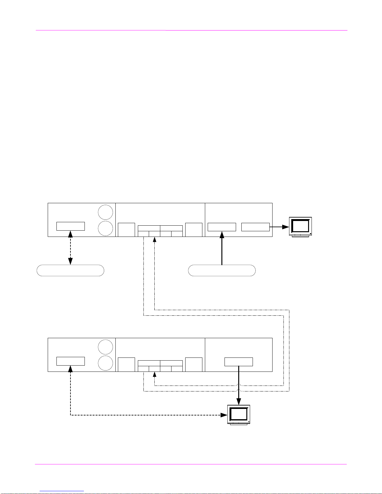
HDMIDaisy‐Chained,Duplex,withRS232serial...............................................................4
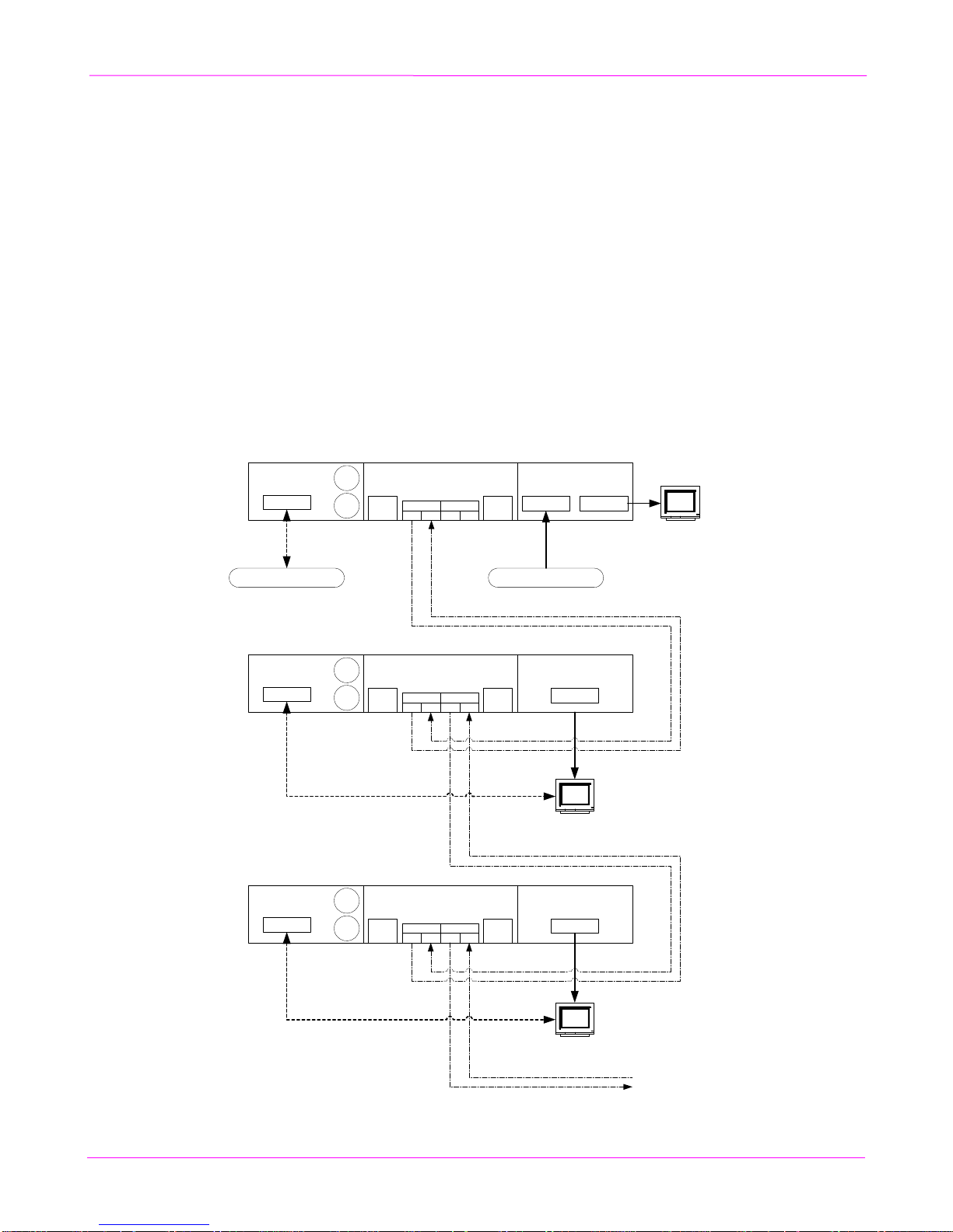
HDMIDaisy‐Chained,Simplex,withRS232serial.............................................................5
ApplicationNotes.....................................................................................................................6
HDMIwithHDCP‐protectedcontent–HDCPKeylimit...............................................6
UsingHDMI(withHDCP‐protectedcontent)withDVIoutputs.................................6
UsingRS232SerialWithDaisy‐ChainedReceivers.........................................................6
RS232PortSettingsandAddressable‐ReceiverOperation.............................................7
Specifications................................................................................................................................8
CommonSpecifications...........................................................................................................8
Coremodules:VG‐TX2,VG‐RX2...........................................................................................9
Fiber‐OpticModules...........................................................................................................10
Videomodule:HDMI‐TX......................................................................................................11
Videomodule:HDMI‐RX......................................................................................................12
Videomodule:DVI‐TX..........................................................................................................13
Videomodule:DVI‐RX..........................................................................................................14
Videomodule:VGA‐TX........................................................................................................15
Auxmodule:ISA....................................................................................................................17
Installation..................................................................................................................................19
Prerequisites............................................................................................................................19
Fiber‐OpticCableRecommendations..................................................................................20
Fiber‐OpticCableTerminology........................................................................................21
Transmitter&ReceiverEarth‐grounding...........................................................................23
Transmitter/ReceiverInstallation.........................................................................................24
VoyagerModularConstruction............................................................................................25
VoyagerModuleDisassemblyProcedure.......................................................................25
VoyagerModuleAssemblyProcedure............................................................................25

<Contents
INSTALLATION AND USER GUIDE vi
LEDStatusIndicators.............................................................................................................26
FrontPanel...........................................................................................................................26
RearPanel............................................................................................................................27
DetailofLEDindicatorblink/flashpatterns...................................................................28
FrontPanelUserInterface........................................................................................................29
EDIDManagementFunctions..............................................................................................29
VGA‐TXControls...................................................................................................................30
Troubleshooting.........................................................................................................................31
AppendixA:ElectricalPinDescriptions................................................................................32
COREmodule:PowerConnector.........................................................................................32
ISAmodule:SerialPort..........................................................................................................33
SerialInterfaceReferenceInformation................................................................................34
ISAmodule:Analog‐AudioPort..........................................................................................37
ISAmodule:IRPort................................................................................................................38
AppendixB:MountingOptions..............................................................................................39
VoyagerRigid‐MountKit......................................................................................................41
AppendixC:SystemDesignDrawings..................................................................................42
AppendixD:RegulatoryComplianceInformation..............................................................43
AppendixE:DefaultInternalEDIDProfileDetails..............................................................44
AppendixF:VGA‐TXImageScalingDetails.........................................................................45

About this Manual
INSTALLATION AND USER GUIDE 1
About this Manual
ThismanualcontainsinformationabouttheMagentaVoyagerseriesofvideoextensionproducts.Thisincludes
thefollowingprimarycomponents:
• VoyagerVG‐TX2:TransmitterCOREmodule,equippedwith2SFPopticalports.
• VoyagerVG‐RX2:ReceiverCOREmodule,equippedwith2SFPopticalports.
• VoyagerHDMI‐TX:TransmitterVIDEOmodule,supportingHDMI/DVIvideoinputusinga
standardHDMIconnector.
• VoyagerHDMI‐RX:ReceiverVIDEOmodule,supportingHDMI/DVIvideooutputusinga
standardHDMIconnector.
• VoyagerDVI‐TX:TransmitterVIDEOmodule,supportingDVIvideoinputusingastandardDVI
connector.
• VoyagerDVI‐RX:ReceiverVIDEOmodule,supportingDVIvideooutputusingastandardDVI
connector.
• VoyagerVGA‐TX:TransmitterVIDEOmodule,supportingVGAandanalogvideoinputsusing
standardHD15(VGA)andRCA/miniDIN(analog)connectors.

Introduction
INSTALLATION AND USER GUIDE 2
Introduction
Magenta’sVoyagerseriesisamodularvideoextensionsystem.Itisfield‐configurabletohandleawidevariety
ofdigitalandanalogvideoformats,extendingtheirreachusingreadilyavailableIT‐gradefiber‐opticcable.
ThesystemisbasedonastandardizedVoyagerCOREmodule,whichprovidestheprimaryimage‐processing
andfiber‐opticlinkfunctionality.TotheCORE,anoptionalVIDEOand/orAUXmodulecanbeeasilyattached.
VIDEOmodulesareofferedindifferentmodels,supportingdigitalandanalogvideoformatsatvirtuallyany
resolutionorrefreshrate.TheAUXmoduleaddssupportforserialRS232,analogstereoaudio,andIR(remote
control)signalextensionaswell.Voyagerextensiontechnologycurrentlysupportsthesesignaltypes:
• Video
oHDMI&DVIdigitalvideo.
oVGA(RGB+HV)analogvideo.
oComposite,component,andY/C(S‐Video)formats.
• Audio
oEmbeddedHDMIaudiostreams(8channels).
oStereoline‐levelanalogaudio.
• Serial
oRS232.Simplexorfull‐duplex.
TheVoyagervideoextensiontechnologycanbeusedinpoint‐to‐pointapplicationsandavarietyofswitched,
distributedanddaisy‐chainedapplicationsaswell.
Note: The IR capability is designed into the hardware, but not currently supported by the firmware. Check with Magenta
Research for applicable firmware updates.

Voyager Applications
INSTALLATION AND USER GUIDE 3
Voyager Applications
TheVoyagerextensionproductscanbeutilizedinavarietyofsystemtopologiestosuitspecificneeds.This
includesbasicpoint‐to‐pointextension,daisy‐chainedextension,switchedvideo(byaddingaVG‐Matrix
switch),andautomatic2:1switchorfailover‐backup(2:1switchatreceiver).Belowaresomeexamplesofthese
configurations.PleasecontactMagentatodiscussyourspecificsystem‐configuration.
Basic HDMI-TX/RX, with RS232
Thisconfigurationexampleshowsaverybasicpoint‐to‐pointextensionapplicationforHDMIvideo.Ifthe
sourcecontentisprotected(withHDCP),thenitwillremainprotectedtothelocalport,andallthewaytothe
receiver’soutput.
IfthesourceprovidesembeddedHDMI‐audio,thatwillbepassedtotheremoteHDMIdisplayunmodified.
TheHDMI‐digitalaudiocanalsobedrivenouttheanalogaudiojacks.
Thereisalsofull‐duplexserial‐controlofthedisplay.Sinceaduplex(twin)fiberisbeingusedbetweentheTX
andRXunits,thedisplayCANsendresponsesbacktothecontrolsystem.Ifasimplex(single)fiberwereused,
thenonlyvideoandserialcanflowTOthedisplay,andnoresponsescanbereturnedtothecontrolsystem.
Figure1.Voyagerpoint‐to‐pointlink,usingHDMI‐TX/RX,withfull‐duplexserialcontrolofdisplay.
HDMI Source
ISA
AUX module
Serial
L/R
IR
HDMI-TX
VIDEO module
HDMI-in HDMI-out
(on front)
Control System
ISA
AUX module
Serial
L/R
IR
HDMI-RX
VIDEO module
HDMI-out
HDMI
Display
HDMI
Display
Duplex (twin)
fiber
VG-TX2 CORE
SFP#1 SFP#2
Pwr USB
(cfg)
TX RX TX RX
Receiver
Transmitter
VG-RX2 CORE
SFP#1 SFP#2
Pwr USB
(cfg)
TX RX TX RX

Voyager Applications
INSTALLATION AND USER GUIDE 4
HDMI Daisy-Chained, Duplex, with RS232 serial
Thisconfigurationexampleshowsadaisy‐chainedDUPLEXmodeextensionapplicationforHDMIvideo.Ifthe
sourcecontentisprotected(withHDCP),thenitwillremainprotectedtothelocalport,andallthewaytoeach
receiver’soutput.Notethatthe“HDCP‐key‐limit”mayapplyinthiscase.SeetheApplicationNotessection.
IfthesourceprovidesembeddedHDMI‐audio,thatwillbepassedtoeachremoteHDMIdisplayunmodified.
Thedigitalaudiocanalsobedrivenouttheanalogaudiojacksasaconfigurableoption(seeMAGui).
Thereisalsofull‐duplexserial‐controlofalldisplays.Sinceaduplex(twin)fiberisbeingusedbetweentheTX
andRXunits,thedisplaysCANsendresponsesbacktothecontrolsystem.Ifasimplex(single)fiberwereused,
thenonlyvideoandserialcanflowTOthedisplay,andnoresponsescanbereturnedtothecontrolsystem.
Ifthedisplaysareserial‐portaddressable,thenthedefaultserialmode(broadcasttoallreceivers)canbe
utilized.Allreturndatawillbemergedtogether–soit’simportantthatonlyonedisplayrespondatatime.If
thedisplaysarenotaddressable,thenit’spossibletomakedistinct“virtualconnections”withindividual
receivers’serialports.
Figure2.Voyagerdaisy‐chainedlink,usingHDMI‐TX/RX,withfull‐duplexserialcontrolofdisplay.
HDMI Source
ISA
AUX module
Serial
L/R
IR
HDMI-TX
VIDEO module
HDMI-in HDMI-out
(on front)
Control System
ISA
AUX module
Serial
L/R
IR
HDMI-RX
VIDEO module
HDMI-out
HDMI
Display
HDMI
Display
Duplex (twin)
fiber
ISA
AUX module
Serial
L/R
IR
HDMI-RX
VIDEO module
HDMI-out
HDMI
Display
Duplex (twin)
fiber
Receiver 1
Receiver 2
VG-TX2 CORE
SFP#1 SFP#2
Pwr USB
(cfg)
TX RX TX RX
VG-RX2 CORE
SFP#1 SFP#2
Pwr USB
(cfg)
TX RX TX RX
VG-RX2 CORE
SFP#1 SFP#2
Pwr USB
(cfg)
TX RX TX RX
Transmitter
Duplex (twin)
fiber
To more
receivers
(optional)

Voyager Applications
INSTALLATION AND USER GUIDE 5
HDMI Daisy-Chained, Simplex, with RS232 serial
Thisconfigurationexampleshowsadaisy‐chainedSIMPLEXmodeextensionapplicationforHDMIvideo.This
configurationwillNOTsupportHDCP‐protectedcontent,sincetheHDCPauthenticationdatafromeach
displaycannotbereturnedtothetransmitter.Ifthesourcecontentisprotected(withHDCP),thentherewillbe
novideooutputarethereceivers.Thelocalportwillstillfunction,however.
IfthesourceprovidesembeddedHDMI‐audio,thatwillbepassedtoeachremoteHDMIdisplayunmodified.
Thedigitalaudiocanalsobedrivenouttheanalogaudiojacksasaconfigurableoption(seeMAGui).
Thereisalsosimplexserial‐controlofalldisplays.Sinceasimplex(single)fiberisbeingused,onlyvideoand
serialcanflowTOthedisplay,butnoresponsescanbereturnedtothecontrolsystem.
Ifthedisplaysareserial‐portaddressable,thenthedefaultserialmode(broadcasttoallreceivers)canbe
utilized.Ifthedisplaysarenotaddressable,thenit’spossibletomakedistinct“virtualconnections”with
individualreceivers’serialports.Inanycase,sincethegeneraloperatingmodeissimplex,noserialdatacanbe
returnedtothetransmitter.
Figure3.Voyagerdaisy‐chainedlink,usingHDMI‐TX/RX,withsimplexserialcontrolofdisplay.
HDMI Source
ISA
AUX module
Serial
L/R
IR
HDMI-TX
VIDEO module
HDMI-in HDMI-out
(on front)
Control System
ISA
AUX module
Serial
L/R
IR
HDMI-RX
VIDEO module
HDMI-out
HDMI
Display
HDMI
Display
Simplex (single)
fiber
ISA
AUX module
Serial
L/R
IR
HDMI-RX
VIDEO module
HDMI-out
HDMI
Display
Receiver 1
Receiver 2
Simplex (single)
fiber
VG-TX2 CORE
SFP#1 SFP#2
Pwr USB
(cfg)
TX RX TX RX
Transmitter
VG-RX2 CORE
SFP#1 SFP#2
Pwr USB
(cfg)
TX RX TX RX
VG-RX2 CORE
SFP#1 SFP#2
Pwr USB
(cfg)
TX RX TX RX
To more receivers
(optional)
To more receivers
(optional)
Simplex (single)
fiber
Simplex (single)
fiber
Simplex (single)
fiber

Voyager Applications
INSTALLATION AND USER GUIDE 6
Application Notes
HDMI with HDCP-protected content – HDCP Key limit
WhenthevideosourceisprotectedHDMIcontent(withHDCP),theremaybealimittothetotalnumberof
displaydevicesallowedforaparticularsourcedevice(PC,BluRayplayer,etc.).
Thislimitationisafunctionofthesourcedevice–nottheVoyagerextension.Sometimesthelimitcanbeaslow
as1,2or3displays.Tobecertain–checkthetechnicaldocumentationforyoursourcedevice,orconducta
benchtesttoconfirmthatyoucanindeeddrivetheactualnumberofdisplaysrequiredforyourapplication.
NotethattheabsolutemaximumnumberofdisplaysforHDCP‐protectedcontentis127,whichisdefinedby
theHDCPcontent‐protectiontechnology.Notallsourcedeviceswillsupportthismaximum.
ForvideoswitchingapplicationsusingtheVoyagerMatrixproducts,pleasecontactMagentaResearchwithany
concernsregardingHDCP“keylimits”.
Using HDMI (with HDCP-protected content) with DVI outputs
WhenthevideosourceisprotectedHDMIcontent(withHDCP),itwillstillbepossibletoviewthatprotected
contentbyusingaDVI‐RXmodule.MostdisplaysequippedwithonlyDVIconnectorsalsoacceptHDMIvideo.
IfthereisanydoubtregardingHDCPsupportwithinaparticulardisplay–thebestwaytoconfirmthisisto
simplytestitfirst.
Using RS232 Serial With Daisy-Chained Receivers
ThefollowingonlyappliesiftheISAauxiliarymoduleisbeingusedwithdaisy‐chainedreceivers:
TheVG‐TX2COREmodulecansendRS232serialtrafficdownstream(toreceivers)usingeither(orboth)optical
portssimultaneously.TheVG‐RXCOREmoduleispre‐configuredtobehaveasfollows:
SerialtrafficreceivedontheOptical‐1portissenttotheISA’sserialportonthisreceiver.Also,thesame
serialtrafficisimmediatelyretransmittedtotheOptical‐2porttothenextreceiverinthedaisy‐chain.
SerialtrafficenteringtheISA’sserialportonthisreceiverisonlysentupstream(totheVG2‐TX)onthe
Optical‐1port.
SerialtrafficreceivedontheOptical‐2portisimmediatelyretransmittedtotheOptical‐1port.

Voyager Applications
INSTALLATION AND USER GUIDE 7
RS232 Port Settings and Addressable-Receiver Operation
ThedefaultRS232portsettingsare:9600baud,8databits,onestopbit,noparity(9600/8/n/1).Thebaudrate
andstop‐bitsettingsareconfigurableusingtheMAGuiutility.
ThedefaultbehaviorfortheISA’sRS232serial‐portistosimplyprovidetheequivalentofa“passthrough”
cablefromthetransmitterendtooneormorereceiverendpoints.Anydatacomingintothetransmitteris
broadcasttoallreceivers.Anydatafromanyreceiverissenttothetransmitter.Iftworeceiverssenddataatthe
sametime–thedatawillcomeoutoftransmitterinterleaved(andeffectivelygarbled).
Insomecases,theabilitytoselectivelycommunicatewithonereceiveratatimeisrequired.Toaddressan
individualreceiver,thecontrollingdeviceatthetransmitter(typicallyaPCorothercontrolsystem)must
transmitthefollowingstring:
[2‐Secquiet]“@xxxxxxxxxxxxxxxx@”[2‐Secquiet]
Note:Thedouble‐quotes(“)arenottransmittedtotheVG‐TX2–onlythecharactersbetweenthem.
Asshown,theaddressingstringmustbedelimitedbeforeandafterwith2secondsofquiet‐line(nodata).Also,
theentirestring(fromfirst@tosecond@,inclusive)mustbetransmittedcompletelywithin2seconds.Ifeither
oftheserulesareviolated,the“addressingcommand”isignoredandtheentirestringispassedthroughtoall
receiversasifitwerenormalbroadcastdata.
Thexx..xxportionofthestringisthe16‐digitaddressofaspecificreceiver.Thisaddresscanbefoundonthe
bottomofthereceiver’sCOREmodule,printedontheID‐labelasshownhereonthisexampleVG‐RXlabel:
Usingtheabovelabelasanexample,toaddressthisreceivertheaddress‐stringwouldbe:
[2‐Secquiet]“@1122334455667788@”[2‐Secquiet]
Oncetheaddresshasbeenselectedsuccessfully,itwillremainaddressed‐receivermodeuntilpoweriscycledat
thetransmitter,OR,bysettingtheaddressbacktobroadcast‐mode.
Toconfigurethetransmitterbacktoitsdefaultbehaviorof“broadcastmode”withoutcyclingpower,usea
receiveraddressofall0’s(zeros).Thisissimply16zerosinarow:“@0000000000000000@”.
Note:Thetotalnumberofcharactersrequiredisalways18:@+16digits+@
Note:TherearemanymorefeaturesandfunctionsavailablethroughtheRS‐232port.Pleaserefertothe
VoyagerProgrammingGuideformorein‐depthinformation.
ReceiverID
(16digits)

Specifications
INSTALLATION AND USER GUIDE 8
Specifications
Common Specifications
ThefollowingtableslistthespecificationscommontoallVoyagerextensionproducts.Subsequentsections
detailthespecificationsforeachindividualVoyagermodule.
Table1.Voyagerfamily,commonspecifications.
ItemDescription
EnvironmentalOperatingtemperature:32to104°F(0to40°C).
Storagetemperature:‐40to+140°F(‐40to+60°C).
Humidity:80%RH,non‐condensing.
EnclosureSteel(0.040”/1mmthick).
Powder‐coatblackpaint,whiteepoxygraphics.
SystemSizeAssumesatypical3‐moduleconfigurationconsistingof
VIDEO+CORE+AUXmodules,dockedtogether:
1.75ʺ(4.45cm)Hx7.75ʺ(19.68)Wx5.25ʺ(13.33cm)D
Weight:2.2lbs(1kg)
MTBF100,000hours.
Warning: Thisequipmentisnotintendedfor,nordoesitsupport,distributionthroughanEthernetor
IT‐relatedcopperorfibernetwork.Donotconnectthesedevicestoanytypeofnetworkingor
telecommunicationsequipment.
Caution: Thisequipmentmayoutputcontinuous,invisiblelaserradiation.Donotlookdirectlyintothe
endsofanyfiber‐opticcables,orintothefiber‐opticportsonthisequipment.
Preventive: Whenafiber‐opticcableisunplugged,useappropriatedust‐capsonthecableendsandin
anyunusedfiber‐opticportstoprotectfromaccidentallaser‐lightexposure,andingressofunwanted
contaminants.

Specifications
INSTALLATION AND USER GUIDE 9
Core modules: VG-TX2, VG-RX2
TheVoyagerCOREmodulesprovidethemainvideo‐processingandfiber‐opticinterfacelogic.Itsupports2
SFP+fiber‐opticmodules.ItalsoprovidespowerforalltheVIDEOandAUXoptionmodules.TheVG‐TX2and
VG‐RX2COREmoduleslookidentical,externally.Theymainlydifferinthefirmwareloadedintothematthe
factory.Theproduct‐IDlabelonthebottomoftheenclosurewillidentifywhichversionoffirmwarewasloaded
atthefactory.
Table2.VoyagerSpecifications:VG‐TX2,VG‐RX2coremodule,transmitter&receiver.
ItemDescription
DCinputpower10to13VDCregulated,3Amax.
Actualtotalsystempowerconsumptiondependsonwhatoptionmodulesare
connectedtotheCORE.PowerconsumptionoftheCOREmodulealoneis
approximately3Watts.
Maximumfiber
length
2km(6600ft)withthe“MMFSFP”fiber‐opticmoduleandOM4grademulti‐mode
fiber.IfusingOM3gradefiberthedistancewillbelimitedtoapproximately1km
(3300ft).
4kmwiththe“SMFSFP4km”fiber‐opticmoduleandOS1(orbetter)gradesingle‐
modefiber.
30kmwiththe“SMFSFP30km”fiber‐opticmoduleandOS1(orbetter)gradesingle‐
modefiber.
NOTE:Seenextsectionforadditionalfiberdistanceratings.
OpticalportsThisCOREmoduleprovides2SFP+fiber‐opticmoduleports.
Theopticalmoduleswillneedtobespecifiedattimeoforder.
Note: It is possible to use 2 different module types in the same CORE module, if both optical
outputs are used but different maximum extension lengths are required. By default, each core
unit ships with one (1) SFP module. Add-on SFP modules are available on the price list.
USB‐ConfigportTheUSBportisforconfigurationonly.Itisatype“B”deviceport.AstandardUSBA‐
BcableistypicallyrequiredtoconnectaCOREtoahost‐PC.
USB‐Configport
Characteristics
TheUSB‐ConfigportsupportshostcomputerswithUSB‐2.0orUSB‐1.1interface
capability.AMagenta‐suppliedUSB‐driverandconfigurationutilityisrequiredtouse
thisconfigurationport.
Connectors(1)CoaxialDCpowerjack(2.1mmpin,5.5mmOD,11mmlong)
(2)SFP+opticalports
(1)USBtype“B”port
(1)Video‐moduledockingconnector.
(1)Aux‐moduledockingconnector.
ModuleSize1.53ʺ(3.88cm)Hx3.27ʺ(8.30cm)Wx5.12ʺ(13cm)D
ModuleWeight0.8lb.(0.37kg)

Specifications
INSTALLATION AND USER GUIDE 10
Fiber-Optic Modules
EachVoyagerVG‐TX2COREmodulehastwoSFP+ports,meantforinsertionof1or2fiber‐opticmodules.The
Voyagerextensionproductscanusethreetypesoffiber‐opticmodules:
• Moduletype=“MMFSFP”.
oMulti‐Mode:Upto2Km(6600ft)extensionoverOM4multi‐modefibercable.
oMulti‐Mode:Upto1Km(3300ft)extensionoverOM3multi‐modefibercable.
oMulti‐Mode:Upto666m(2200ft)extensionoverOM2multi‐modefibercable.
oMulti‐Mode:Upto496m(1640ft)extensionoverOM1multi‐modefibercable.
• Moduletype=“SMFSFP4km”.
oSingle‐mode:Upto4Km(13200ft)extensionoversingle‐modefibercable.
• Moduletype=“SMFSFP30km”.
oSingle‐mode:Upto30Km(99000ft)extensionoversingle‐modefibercable.
Thefiber‐opticmodulesusedwithVoyagerproductshavebeenthoroughlytestedandareMagentaapproved.
Toensuremaximumsystemperformanceandreliability,donotattempttousenon‐Magentaapprovedoptical
modules.
Note:Bothmulti‐modeandsingle‐modemodulescanbeutilizedinSimplexandDuplexVoyagersystem
configurations.Theterms“Simplex”and“Duplex”refertohowtheVoyagertransmittersandreceiversare
interlinkedwithfiber.TheydoNOTrefertothetypeoffiberortypeoffiber‐opticmodulesbeingused.
Note:ItispossibletousedifferentmoduletypesinthesameCOREmodule.Sometimesbothopticaloutputsare
neededbutdifferentmaximumextensionlengthsarerequiredforaspecificapplication.
Table3.VoyagerSpecifications:Model“MMFSFP”,Multi‐modefiber‐opticmodule.
ItemDescription
Form‐factorIndustry‐standard“SFP+”module.
Opticalports2fiberports:TXandRX(full‐duplexcapable),type“LC”fiber‐optic
connector.
Wavelength850nm
Table4.VoyagerSpecifications:Model“SMFSFP4km”,Single‐modefiber‐opticmodules,4kmcapable.
ItemDescription
Form‐factorIndustry‐standard“SFP+”module.
Opticalports2fiberports:TXandRX(full‐duplexcapable),type“LC”fiber‐optic
connector.
Wavelength1310nm
Table5.VoyagerSpecifications:Model“SMFSFP30km”,Single‐modefiber‐opticmodules,30kmcapable.
ItemDescription
Form‐factorIndustry‐standard“SFP+”module.
Opticalports2fiberports:TXandRX(full‐duplexcapable),type“LC”fiber‐optic
connector.
Wavelength1310nm

Specifications
INSTALLATION AND USER GUIDE 11
Video module: HDMI-TX
TheHDMI‐TXmoduleacceptsHDMIvideo(andDVI,viaaplug‐adapterorcable‐adapter)asaninputsignal.
Thereisalsoalocal‐outputportwhichisoftenusedforalocalHDMI(orDVI)displayfortestordebugging
purposes.
Table6.VoyagerHDMI‐TXModuleSpecifications
ItemDescription
DCinputpowerProvidedbytheCOREmodule.However,powerconsumptionofthismodulealoneis
approximately0.5watts.
VideoSupportVideoinputformats(videoinputport):
• Maximumresolutionsupported=1080por1920x1200.
• Maximumcolor‐depth=24bitsperpixel(8bitspercolor).
• Maximumrefreshrate=60Hz@1920x1200.
Videooutputformats(localoutputport):Thelocalportisessentiallyadirectcopyof
thevideoinputport.However,theoutputvideocolor‐spaceisalwaysRGBregardless
oftheinputvideocolor‐space.
Audio
Characteristics
Thismodulerecognizesall8channels(ifpresent)ofembeddedHDMIaudio,passing
themthroughthesystemtothereceiver.
Connectors(1)HDMI‐input,(1)HDMI‐output,(1)COREdockingconnector
ModuleSize1.53ʺ(3.88cm)Hx2.16ʺ(5.48cm)Wx5.12ʺ(13cm)D
ModuleWeight0.6lb.(0.27kg)
EDID/DDCThismodulesupportstheEDID/DDCconnectionsontheHDMIconnectors.
HDMIVersion1.3b
HDCPVersion1.1.Classification:HDCPRepeaterDevice
CECTheHDMI“CEC”interfaceprotocolisnotcurrentlysupported.
Note:Thehardwareiscapable.Afuturefirmwareupgrademayenablethis
functionality.
TheHDMI‐TXhardwareiscapableof30‐bitcolor.However,thismodeisnotyetenabledbythefirmware.
CheckwithMagentaResearchforapplicablefirmwareupdates.

Specifications
INSTALLATION AND USER GUIDE 12
Video module: HDMI-RX
TheHDMI‐RXmoduleprovidesHDMIvideo(andDVI,viaaplug‐adapterorcable‐adapter)asanoutput
signal.Thismodulesupports1displayoutput.
Table7.VoyagerHDMI‐RXModuleSpecifications
ItemDescription
DCinputpowerProvidedbytheCOREmodule.However,powerconsumptionofthismodulealoneis
approximately0.5watts.
VideoSupportVideooutputformats:
• Maximumresolutionsupported=1080por1920x1200.
• Maximumcolor‐depth=24bitsperpixel(8bitspercolor).
• Maximumrefreshrate=60Hz@1920x1200.
Audio
Characteristics
ThismoduleautomaticallyprovidesembeddedHDMI‐audio(ifaudioisavailableat
thesourceANDiftheEDIDinthesinkordisplaydevicesupportsit).
*Foranalog‐audiooutput,pleaseusetheISAauxiliarymodule.
Connectors(1)HDMI‐output,(1)COREdockingconnector
ModuleSize1.53ʺ(3.88cm)Hx2.16ʺ(5.48cm)Wx5.12ʺ(13cm)D
ModuleWeight0.6lb.(0.27kg)
EDID/DDCThismodulesupportstheEDID/DDCconnectionsontheHDMIconnector.
HDMIVersion1.3b
HDCPVersion1.1.Classification:HDCPRepeaterDevice
CECTheHDMI“CEC”interfaceprotocolisnotcurrentlysupported.Note:Thehardwareis
capable.Afuturefirmwareupgrademayenablethisfunctionality.
TheHDMI‐RXhardwareiscapableof30‐bitcolor.However,thismodeisnotyetenabledbythefirmware.
CheckwithMagentaResearchforapplicablefirmwareupdates.

Specifications
INSTALLATION AND USER GUIDE 13
Video module: DVI-TX
TheDVI‐TXmoduleacceptsDVIvideoasaninputsignal.Thereisalsoalocal‐outputportwhichisoftenused
foralocalDVIdisplayfortestordebuggingpurposes.
Table8.VoyagerDVI‐TXModuleSpecifications
ItemDescription
DCinputpowerProvidedbytheCOREmodule.However,powerconsumptionofthismodulealoneis
approximately0.5watts.
VideoSupportVideoinputformats(videoinputport):
• Maximumresolutionsupported=1080por1920x1200.
• Maximumcolor‐depth=24bitsperpixel(8bitspercolor).
• Maximumrefreshrate=60Hz@1920x1200.
Videooutputformats(localoutputport):
Thelocalportisessentiallyadirectcopyofthevideoinputport.However,the
outputvideocolor‐spaceisalwaysRGBregardlessoftheinputvideocolor‐
space.
Audio
Characteristics
Embeddeddigitalaudioisnotsupported.
*Foranalog‐audiooutput,pleaseusetheISAauxiliarymodule.
Connectors(1)DVI‐input,(1)DVI‐output,(1)COREdockingconnector
ModuleSize1.53ʺ(3.88cm)Hx2.16ʺ(5.48cm)Wx5.12ʺ(13cm)D
ModuleWeight0.6lb.(0.27kg)
EDID/DDCThismodulesupportstheEDID/DDCconnectionsontheDVIconnectors.
HDMIVersion1.3b.ProtectedHDMIcontentissupported.However,itisusuallypossiblevia
aplug‐adapterorcable‐adaptertointerfacewithanHDMIsourceordisplaydevice.
HDCPVersion1.1.Classification:HDCPRepeaterDevice
CECTheDVIinterfacestandarddoesnotsupporttheCECsignal.
TheDVI‐TXhardwareiscapableof30‐bitcolor.However,thismodeisnotyetenabledbythefirmware.
CheckwithMagentaResearchforapplicablefirmwareupdates.

Specifications
INSTALLATION AND USER GUIDE 14
Video module: DVI-RX
TheDVI‐RXmoduleprovidesDVIvideoasanoutputsignal.Thismodulesupports1displayoutput.
Table9.VoyagerDVI‐RXModuleSpecifications
ItemDescription
DCinputpowerProvidedbytheCOREmodule.However,powerconsumptionofthismodulealoneis
approximately0.5watts.
VideoSupportVideooutputformats:
• Maximumresolutionsupported=1080por1920x1200.
• Maximumcolor‐depth=24bitsperpixel(8bitspercolor).
• Maximumrefreshrate=60Hz@1920x1200.
Audio
Characteristics
Thismoduleautomaticallyprovidesembeddeddigitalaudio(ifaudioisavailableat
thesource).*Foranalog‐audiooutput,pleaseusetheISAauxiliarymodule.
Connectors(1)DVI‐output,(1)COREdockingconnector
ModuleSize1.53ʺ(3.88cm)Hx2.16ʺ(5.48cm)Wx5.12ʺ(13cm)D
ModuleWeight0.6lb.(0.27kg)
EDID/DDCThismodulesupportstheEDID/DDCconnectionsontheDVIconnector.
HDMIVersion1.3b.ProtectedHDMIcontentissupported.However,itisusuallypossiblevia
aplug‐adapterorcable‐adaptertointerfacewithanHDMIdisplaydevice.
HDCPVersion1.1.Classification:HDCPRepeaterDevice
CECTheDVIinterfacestandarddoesnotsupporttheCECsignal.
TheDVI‐RXhardwareiscapableof30‐bitcolor.However,thismodeisnotyetenabledbythefirmware.
CheckwithMagentaResearchforapplicablefirmwareupdates.
Table of contents
Other Magenta Research Transmitter manuals
Popular Transmitter manuals by other brands

E+E Elektronik
E+E Elektronik EE210 user guide

Extron electronics
Extron electronics XTP T HWP 101 Setup guide

Honeywell
Honeywell 5815-1 installation instructions

GE
GE Hart Druck RTX 1000H Series user manual

Siemens
Siemens SITRANS T Series operating instructions

RKI Instruments
RKI Instruments 65-2335RK Operator's manual