Circutor SVGm-4WF-030M-400 User manual

SVGm
(M248B01-03-19A)
Static var generator
INSTRUCTION MANUAL

2
SVGm
Instruction Manual
3
Instruction Manual
SVGm
SAFETY PRECAUTIONS
DANGER
Warns of a risk, which could result in personal injury or material damage.
ATTENTION
Indicatesthatspecialattentionshouldbepaidtoaspecicpoint.
Follow the warnings described in this manual with the symbols shown below.
If you must handle the unit for its installation, start-up or maintenance, the following
should be taken into consideration:
Incorrect handling or installation of the unit may result in injury to personnel as well as damage
to the unit. In particular, handling with voltages applied may result in electric shock, which may
cause death or serious injury to personnel. Defective installation or maintenance may also
leadtotheriskofre.
Read the manual carefully prior to connecting the unit. Follow all installation and maintenance
instructions throughout the unit’s working life. Pay special attention to the installation stan-
dards of the National Electrical Code.
Refer to the instruction manual before using the unit
In this manual, if the instructions marked with this symbol are not respected or carried out correctly, it can
result in injury or damage to the unit and /or installations.
CIRCUTOR,SAreservestherighttomodifyfeaturesortheproductmanualwithoutpriornotication.
DISCLAIMER
CIRCUTOR, SAreservestherighttomakemodicationstothedeviceortheunitspecica-
tions set out in this instruction manual without prior notice.
CIRCUTOR, SA on its web site, supplies its customers with the latest versions of the device
specicationsandthemostupdatedmanuals.
www.circutor.com
CIRCUTOR, recommends using the original cables and accessories that are
supplied with the device.

4
SVGm
Instruction Manual
CONTENTS
SAFETY PRECAUTIONS ���������������������������������������������������������������������������������������������������������������������������������������3
DISCLAIMER ����������������������������������������������������������������������������������������������������������������������������������������������������������3
CONTENTS�������������������������������������������������������������������������������������������������������������������������������������������������������������4
REVISION LOG�������������������������������������������������������������������������������������������������������������������������������������������������������6
SYMBOLS���������������������������������������������������������������������������������������������������������������������������������������������������������������6
1�- VERIFICATION UPON RECEPTION�����������������������������������������������������������������������������������������������������������������7
1�1�- RECEPTION PROTOCOL�������������������������������������������������������������������������������������������������������������������������7
1�2�- TRANSPORT AND HANDLING ����������������������������������������������������������������������������������������������������������������7
1�3�- STORAGE��������������������������������������������������������������������������������������������������������������������������������������������������9
2�- PRODUCT DESCRIPTION������������������������������������������������������������������������������������������������������������������������������10
3�- DEVICE INSTALLATION ��������������������������������������������������������������������������������������������������������������������������������� 13
3�1�- PRELIMINARY RECOMMENDATIONS �������������������������������������������������������������������������������������������������� 13
3�2�- INSTALLATION LOCATION�������������������������������������������������������������������������������������������������������������������� 14
3�2�1�- VENTILATION REQUIREMENTS ����������������������������������������������������������������������������������������������������� 14
3�3�- STORAGE FOR LONG PERIODS ����������������������������������������������������������������������������������������������������������16
3�4�- INSTALLATION ��������������������������������������������������������������������������������������������������������������������������������������� 16
3�4�1�- WALL-TYPE SVGm��������������������������������������������������������������������������������������������������������������������������� 16
3�4�2�- RACK-TYPE SVGm ������������������������������������������������������������������������������������������������������������������������� 17
3�4�3�- CABINET-TYPE SVGm ��������������������������������������������������������������������������������������������������������������������� 18
3�5�- CONNECTION �����������������������������������������������������������������������������������������������������������������������������������������19
3�6�- DEVICE TERMINALS������������������������������������������������������������������������������������������������������������������������������21
3�6�1�- WALL-TYPE SVGm : SVGm-xxx-030M, SVGm-xxx-060M and SVGm-xxx-100M ��������������������� 21
3�6�2�- RACK-TYPE SVGm : SVGm-xxx-100R �������������������������������������������������������������������������������������������23
3�6�3�- CABINET-TYPE SVGm : SVGm-xxx-100C, SVGm-xxx-200C, SVGm-xxx-300C AND SVGm-xxx-
400C��������������������������������������������������������������������������������������������������������������������������������������������������������������24
3�7�- CONNECTION DIAGRAMS �������������������������������������������������������������������������������������������������������������������� 27
3�7�1�- 4-WIRE CONNECTION AND CURRENT MEASUREMENT ON THE MAINS SIDE� ����������������������� 27
3�7�2�- 4-WIRE CONNECTION AND CURRENT MEASUREMENT ON THE LOAD SIDE�������������������������� 28
3�7�3�- 3-WIRE CONNECTION AND CURRENT MEASUREMENT ON THE MAINS SIDE� ����������������������� 29
3�7�4�- 3-WIRE CONNECTION AND CURRENT MEASUREMENT ON THE LOAD SIDE�������������������������� 30
3�7�5�- 3-WIRE CONNECTION AND 2 CURRENT TRANSFORMERS ON THE MAINS SIDE� ������������������ 31
3�7�6�- 3-WIRE CONNECTION AND 2 CURRENT TRANSFORMERS ON THE LOAD SIDE��������������������� 32
3�8�- PARALLEL CONNECTION OF 2 TO 100 SVGm ����������������������������������������������������������������������������������� 33
3�8�1�- CONNECTING INDIVIDUAL DEVICES��������������������������������������������������������������������������������������������� 34
3�8�2�- CONNECTING CABINETS���������������������������������������������������������������������������������������������������������������� 35
4�- OPERATION ���������������������������������������������������������������������������������������������������������������������������������������������������36
4�1�- OPERATING PRINCIPLE ������������������������������������������������������������������������������������������������������������������������ 36
4�2�- SELF-DIAGNOSIS����������������������������������������������������������������������������������������������������������������������������������� 37
4�3�- DISPLAY ��������������������������������������������������������������������������������������������������������������������������������������������������37
4�3�1�- UPPER AREA������������������������������������������������������������������������������������������������������������������������������������ 38
4�3�2�- CENTRAL AREA ������������������������������������������������������������������������������������������������������������������������������� 38
4�3�3�- LOWER AREA����������������������������������������������������������������������������������������������������������������������������������� 39
5�- START-UP�������������������������������������������������������������������������������������������������������������������������������������������������������� 40
6�- DISPLAY ����������������������������������������������������������������������������������������������������������������������������������������������������������41
6�1�- MAIN SCREEN ���������������������������������������������������������������������������������������������������������������������������������������� 41
6�1�1� - DEVICE SINGLE OR MASTER�������������������������������������������������������������������������������������������������������� 41
6�1�2� - DEVICE SLAVE ��������������������������������������������������������������������������������������������������������������������������������42
6�2�- VOLTAGE, CURRENT AND FREQUENCY��������������������������������������������������������������������������������������������� 43
6.3.- POWER AND COS ɸ OF MAINS������������������������������������������������������������������������������������������������������������43
6.4.- POWER AND COS ɸ OF LOAD ������������������������������������������������������������������������������������������������������������ 44
6�5�- MAINS PHASORS�����������������������������������������������������������������������������������������������������������������������������������45
6�6�- LOAD PHASORS ������������������������������������������������������������������������������������������������������������������������������������45
6�7�- ALARMS ��������������������������������������������������������������������������������������������������������������������������������������������������46
6�8�- WARNINGS ���������������������������������������������������������������������������������������������������������������������������������������������47
6�9�- TEMPERATURE �������������������������������������������������������������������������������������������������������������������������������������� 50
6�10�- ETHERNET COMMUNICATIONS ���������������������������������������������������������������������������������������������������������50
6�11�- DEVICE INFORMATION������������������������������������������������������������������������������������������������������������������������51
6�12�- SLAVE DEVICE STATUS ����������������������������������������������������������������������������������������������������������������������52
7�- CONFIGURATION �������������������������������������������������������������������������������������������������������������������������������������������53

5
Instruction Manual
SVGm
7�1�- LANGUAGE���������������������������������������������������������������������������������������������������������������������������������������������54
7�2�- DEVICE SPECIFICATIONS ��������������������������������������������������������������������������������������������������������������������� 54
7�3�- INSTALLED DEVICES�����������������������������������������������������������������������������������������������������������������������������55
7�4�- OPERATING LIMITS �������������������������������������������������������������������������������������������������������������������������������56
7�5�- TRANSFORMER CONFIGURATION ������������������������������������������������������������������������������������������������������ 57
7�6�- ETHERNET COMMUNICATIONS ����������������������������������������������������������������������������������������������������������� 58
7�7�- RS-485 COMMUNICATIONS������������������������������������������������������������������������������������������������������������������59
7�8�- DATE / TIME ��������������������������������������������������������������������������������������������������������������������������������������������59
7�9�- SAVE DATA ���������������������������������������������������������������������������������������������������������������������������������������������60
8�- RS-485 COMMUNICATIONS���������������������������������������������������������������������������������������������������������������������������61
8�1�- CONNECTIONS���������������������������������������������������������������������������������������������������������������������������������������61
8�2�- PROTOCOL���������������������������������������������������������������������������������������������������������������������������������������������62
8�2�1�- EXAMPLE OF MODBUS QUERY ����������������������������������������������������������������������������������������������������� 62
8�2�2�- MODBUS MAP ����������������������������������������������������������������������������������������������������������������������������������62
9�- ETHERNET COMMUNICATIONS �������������������������������������������������������������������������������������������������������������������66
9�1�- CONNECTION �����������������������������������������������������������������������������������������������������������������������������������������66
9�2�- WEB SITE������������������������������������������������������������������������������������������������������������������������������������������������66
10�- MAINTENANCE���������������������������������������������������������������������������������������������������������������������������������������������68
10�1�- STANDARD MAINTENANCE���������������������������������������������������������������������������������������������������������������� 68
10�2�- COOLING FANS������������������������������������������������������������������������������������������������������������������������������������70
10�3�- CHANGE OF COOLING FANS: SVGm OF 30 kvar����������������������������������������������������������������������������� 71
10�4�- CHANGE OF COOLING FANS: SVGm OF 60 kvar����������������������������������������������������������������������������� 73
10�5�- CHANGE OF COOLING FANS: SVGm OF 100 kvar RACK ��������������������������������������������������������������� 76
10�6�- CHANGE OF COOLING FANS: SVGm OF 100 kvar WALL���������������������������������������������������������������� 79
10�7�- CHANGE OF COOLING FANS: CABINET TYPE SVGm �������������������������������������������������������������������� 81
11�- TECHNICAL FEATURES�������������������������������������������������������������������������������������������������������������������������������82
12�- TECHNICAL SERVICE����������������������������������������������������������������������������������������������������������������������������������91
13�- GUARANTEE�������������������������������������������������������������������������������������������������������������������������������������������������91
14�- CE CERTIFICATE������������������������������������������������������������������������������������������������������������������������������������������92
6
SVGm
Instruction Manual
REVISION LOG
Table 1: Revision log�
Date Revision Description
03/19 M248B01-03-19A Initial Version
SYMBOLS
Table 2: Symbols�
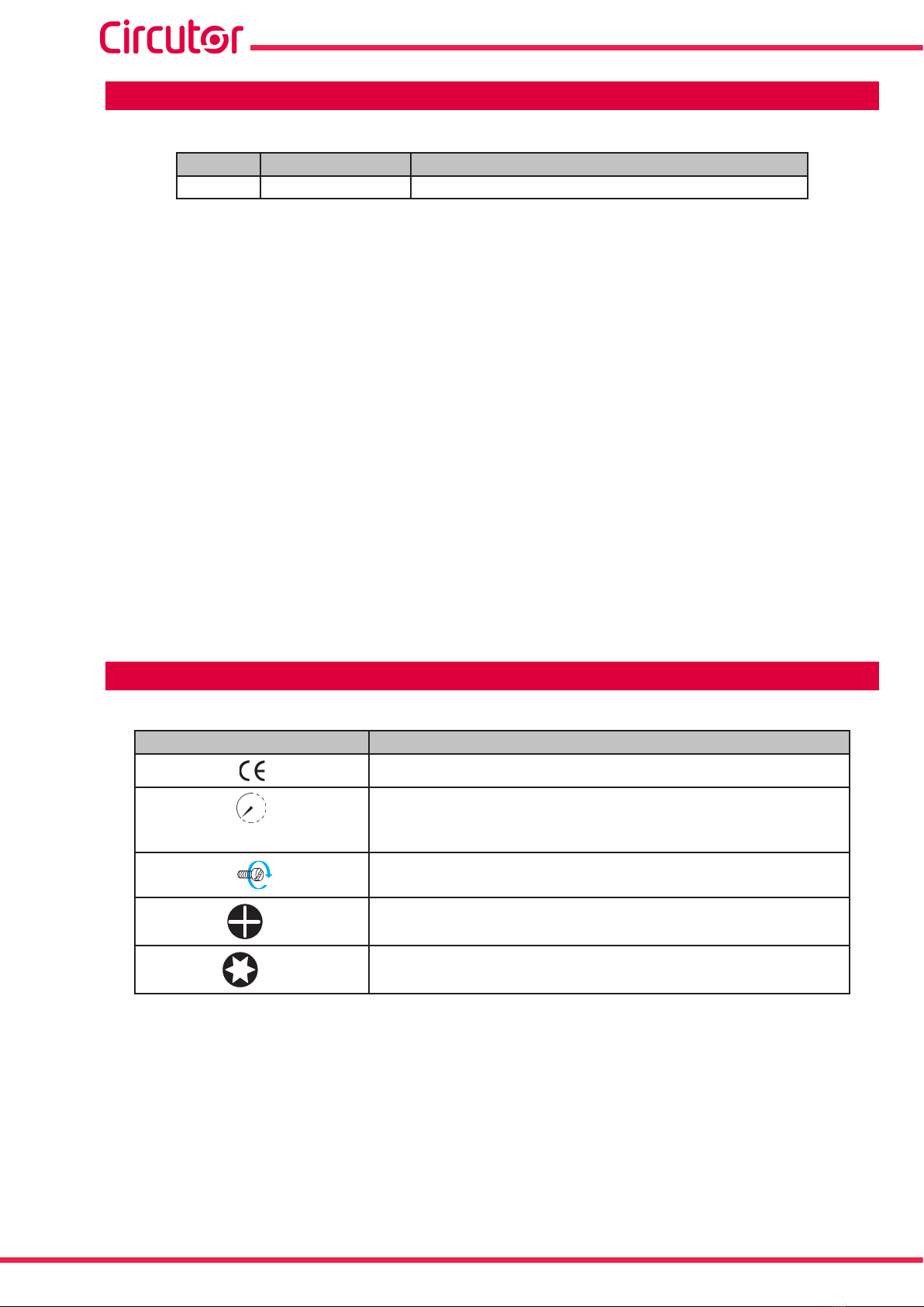
Symbol Description
Compliant with the relevant European standards.
1 min
After disconnecting the device from all power supplies, wait 1 minute before
performing any operations.
Torque
2Screwdriver for PH2 head screws
30 Screwdriver for Torx 30 head screws

7
Instruction Manual
SVGm
1�- VERIFICATION UPON RECEPTION
1.1.- RECEPTION PROTOCOL
Check the following points when you receive the device:
a)Thedevicemeetsthespecicationsdescribedinyourorder.
b) The device has not suffered any damage during transport.
c) Perform an external visual inspection of the device prior to switching it on.
d) Check that it has been delivered with the following:
- Instruction manual
- Communication cable for connecting devices in parallel.(Models SVGm Wall
and Rack type).
e) Perform an external and internal visual inspection of the device prior to connecting it.
If any problem is noticed upon reception, immediately contact the transport
company and/or CIRCUTOR's after-sales service.
1.2.- TRANSPORT AND HANDLING
The transport, loading and unloading and handling of the device must be car-
ried out with proper precautions and using the proper manual and mechanical
tools so as not to damage it.
If the device is not to be immediately installed, it must be stored at a location
witharmandleveloor,andthestorageconditionslistedinthetechnical
features section must be observed. In this case, it is recommended that the
device be stored with its original protective packaging.
Tomovethedeviceashortdistance,thedevice’soorsupportprolesfacilitatehandlingwith
a pallet jack or forklift. (Figure 1)
Figure 1: Transport with pallet jack�

8
SVGm
Instruction Manual
The centre of gravity of some devices may be found at a considerable height.
Therefore, when handling with a forklift, it is recommended that the device be
securely fastened and that no abrupt manoeuvres made. The device should
not be lifted more than 20 cm off the ground
When unloading and moving the device, use a forklift with forks long enough to support the en-
tire length of the base. Otherwise, the forks should be long enough to support at least ¾ of said
depth.Theforksmustbeatandsupportedrmlybythebase.Raisethedevicebyplacingthe
forksunderneaththeprolethatsupportsthedevice.(Figure 2).
There might be an offset in the centre of gravity from the centre of the cabinet,
as a result of the uneven distribution of loads inside the device. The neces-
sary precautions must be taken to prevent the device from tipping over during
abrupt operations.
Figure 2: Unloading with a forklift�
When unpacking the device, pay attention to prevent damaging the device if you are using cut-
ting tools, such as cutters, scissors or knives.
The SVGm devices cabinet type, there are also 4 rings (diameter : 28 mm) in the top panel so
that they can be transported by a crane. The top panel is inverted, but the rings are mounted,
to enable it to be transported without any prior set-up required. The angle of the cables must
be greater than 45º
Figure 3: Transport of an cabinet SVGm by crane�

9
Instruction Manual
SVGm
1.3.- STORAGE
The device should be stored according to the following recommendations:
Avoid placing them on uneven surfaces.
Do not store them in outdoor areas, humid areas or areas exposed to splashing wa-
ter.
Avoid hot spots (maximum ambient temperature: 50ºC)
Avoid salty and corrosive environments.
Avoid storing the devices in areas where a lot of dust is generated or where the risk
of chemical or other types of contamination is present.
10
SVGm
Instruction Manual
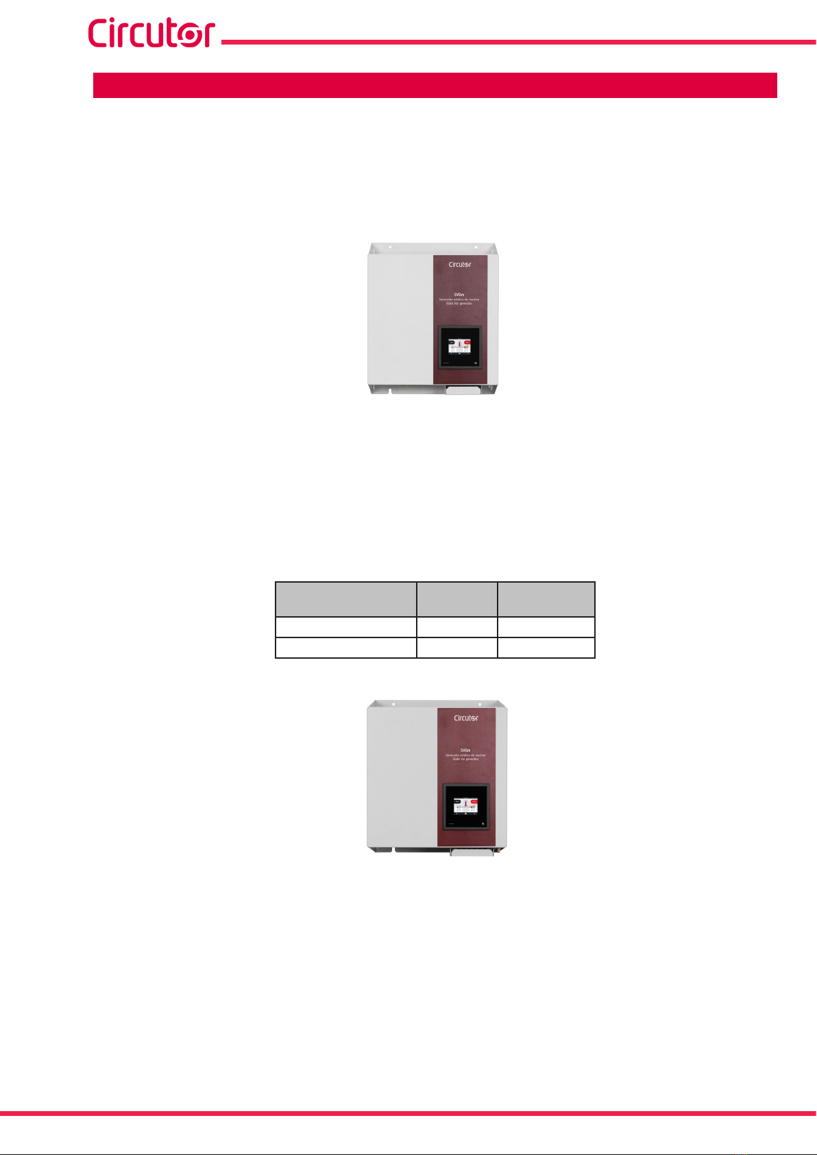
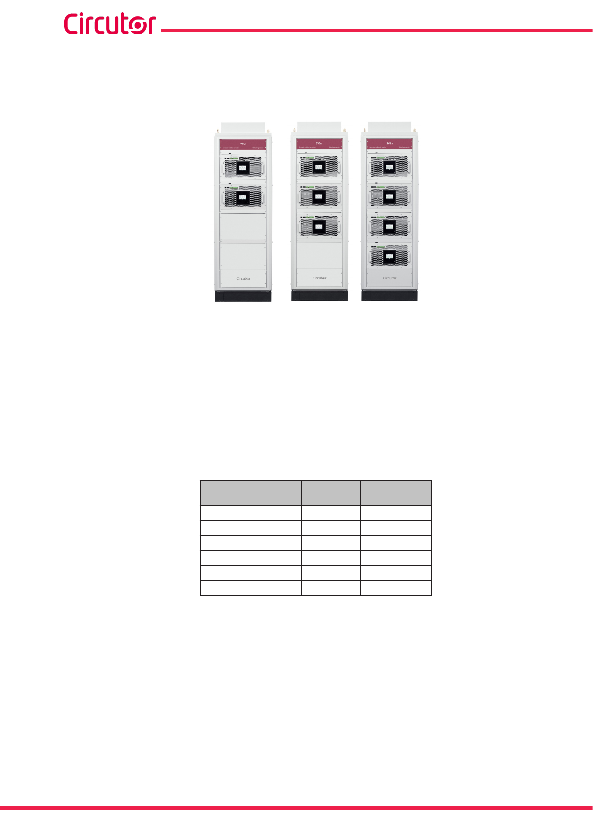
2�- PRODUCT DESCRIPTION
The SVG static var generator can be used to correct the power factor. For both backward (in-
ductive) and forward (capacitive) currents.
There are different models of the device, for different currents:
SVGm 30 kvar,
The device features:
- 3/4-wire multifunction, for installation in three-phase mains with or without neutral.
- Parallel installation of up to 100 devices.
- EMI lters.
- LCD touch display, to view the parameters.
-RS-485 and Ethernet communications.
- Wall enclosure.
Table 3:Relation of models SVGm of 30 kvar�
Model 3 Wires
( L1, L2, L3)
4 Wires
( L1, L2, L3, N)
SVGm-3WF-030M-480 -
SVGm-4WF-030M-400 -
SVGm 60 kvar,
The device features:
- 3/4-wire multifunction, for installation in three-phase mains with or without neutral.
- Parallel installation of up to 50 devices.
- EMI lters.
- LCD touch display, to view the parameters.
-RS-485 and Ethernet communications.
- Wall enclosure.
11
Instruction Manual
SVGm
Table 4:Relation of models SVGm of 60 kvar�
Model 3 Wires
( L1, L2, L3)
4 Wires
( L1, L2, L3, N)
SVGm-3WF-060M-480 -
SVGm-4WF-060M-400 -
SVGm 100 kvar,
The device features:
- 3/4-wire multifunction, for installation in three-phase mains with or without neutral.
- Parallel installation of up to 100 devices.
- LCD touch display, to view the parameters.
-RS-485 and Ethernet communications.
- EMI lters.
-Enclosure type Rack, Cabinet oWall�
Table 5:Relation of models SVGm of 100 kvar�
Model 3 Wires
( L1, L2, L3)
4 Wires
( L1, L2, L3, N)
Type
Rack Cabinet Wall
SVGm-3WF-100M-480 - - -
SVGm-4WF-100M-400 -- -
SVGm-3WF-100C-480 - - -
SVGm-4WF-100C-400 ---
SVGm-3WF-100R-480 -- -
SVGm-4WF-100R-400 - - -
12
SVGm
Instruction Manual
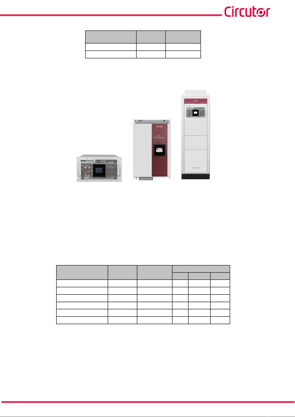
SVGm 200 kvar, 300 kvar and 400 kvar
The 200 kvar is a Cabinet model with two 100 kvar devices connected in parallel; the 300
kvar model has three devices connected, and the 400 kvar model has four.
The device features:
- 3/4-wire multifunction, for installation in three-phase mains with or without neutral.
- Parallel installation of up to 50 devices (Model 200 kvar), 30 devices (Model 300 kvar)
and 25 devices (Model 400 kvar).
- LCD touch display, to view the parameters.
-RS-485 and Ethernet communications.
-Cabinet-type enclosure.
- EMI lters.
Table 6:Relation of models SVGm of 200kvar, 300kvar and 400kvar�
Model 3 Wires
( L1, L2, L3)
4 Wires
( L1, L2, L3, N)
SVGm-3WF-200C-480 -
SVGm-4WF-200C-400 -
SVGm-3WF-300C-480 -
SVGm-4WF-300C-400 -
SVGm-3WF-400C-480 -
SVGm-4WF-400C-400 -
13
Instruction Manual
SVGm
3�- DEVICE INSTALLATION
3.1.- PRELIMINARY RECOMMENDATIONS
The device installation and the maintenance operations must only be car-
ried out by authorised and qualied personnel.
In order to use the device safely, it is critical that individuals who handle it follow
the safety measures set out in the standards of the country where it is being used,
use the personal protective equipment necessary (rubber gloves, face protection
andapprovedame-resistantclothing)topreventinjuriesduetoelectricshockor
electric arc due to exposure to current-carrying conductors and pay attention to
the various warnings indicated in this instruction manual.
Incorrectinstallationorcongurationofthedevicecouldcauseseriousdamage
to the device itself and to other devices of the installation.
Only suitable for assembly on concrete or other non-combustible surfaces, and in
restricted access areas.
The devices are not intended for use in life support, medical safety equipment or
similar applications, whereby a fault in the device could cause loss of life or phys-
ical injury. They are neither intended for military or defence applications. They
should be installed in areas with restricted access.
Disconnect the main switch before starting any maintenance task on the
static generators�
Make sure the device is properly earthed before powering up. Any fault in the
earth connection might cause a risk of electrocution to the user and damage to
the device itself in the case of lightning or other transients.
Before handling the current transformers, ensure that the secondary is short-cir-
cuited. Never open a current transformer secondary under load.
14
SVGm
Instruction Manual
3.2.- INSTALLATION LOCATION
The device must be installed in an environment where the temperature outside the cabinet is
between -10ºC and 45ºC, with a maximum humidity of 95% without condensation.
Do not install the device close to a hot spot and keep it out of direct sunlight.
Install the SVGminaplaceprotectedfromwater,dust,ammableliquids,gases
and corrosive substances.
Make sure there are no power factor correction devices installed in the same
mains as the SVGm.
If there are any compensation devices, these must be detuned in order to avoid
interference between them and the SVGm.
3�2�1�- VENTILATION REQUIREMENTS
3�2�1�1�- Wall-type SVGm
The device has a power control system that controls the rotation speed of the fans and the
maximum power of the device according to the internal temperature, to ensure the best perfor-
mance in any condition.
Table 7: Ventilation distances: Wall-type SVGm�
Ventilation distances : Wall-type SVGm
50 mm 400 mm
3�2�1�2�- Rack-type SVGm
The Rack-type SVGm uses a forced ventilation cooling system, with an air inlet on the front
panel and an air outlet at the back of the device.
Onceinstalled,thedevice’sowsofinletairandoutletairmustbeallowedtocirculatefreely.At
maximum power, the Rack-type SVGmcirculatesanairowof375 m3/h.
The device has a power control system that controls the rotation speed of the fans and the
maximum power of the device according to the internal temperature, to ensure the best perfor-
mance in any condition.
To maintain the device’s performance, we recommend ensuring that the air circulates freely
through the front panel of the Rack-type SVGm, and that the rear is free of obstacles, with a
gap of at least 300 mm.

15
Instruction Manual
SVGm
It should be noted that, depending on the installation conditions in the cabinet and in the room
wherethisisplaced,theoutowsofhotairmaybesuckedbackinbythedevice’sfans,causing
a feedback of hot air that will lower the performance of the device.
It is also necessary to bear in mind the power dissipated by the device when choosing where to
install it, to ensure proper air recirculation, to make sure that the intake air is a suitable temper-
ature. See “11.- TECHNICAL FEATURES”.
Table 8: Ventilation distances: Rack-type SVGm�
Ventilation distances : Rack-type SVGm
300 mm 300 mm
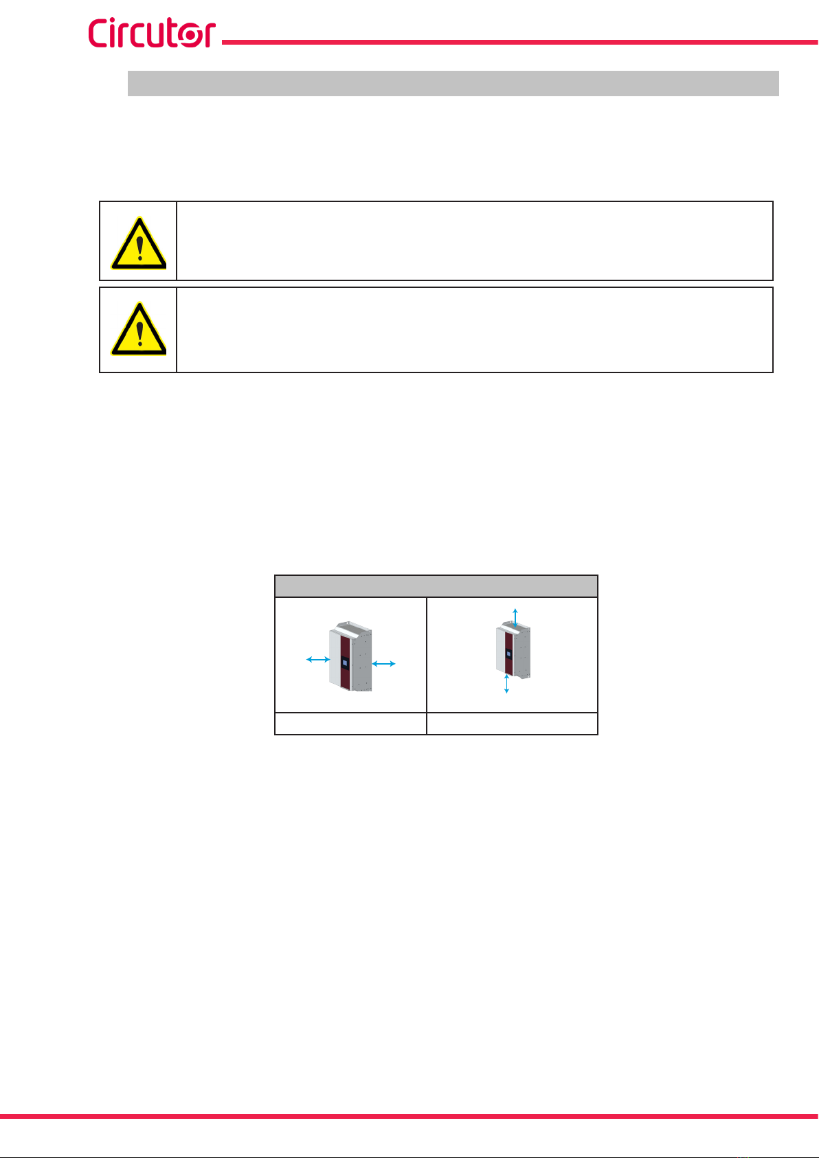
3�2�1�3�- Cabinet-type SVGm
The cabinet-type SVGm uses a forced ventilation cooling system, with an air inlet on the front
panel and an air outlet at the back of the device.
The ventilation grille at the top must not be blocked, leaving enough space to the ceiling to allow
the heat to dissipate. The distance depends on the characteristics of the installation site.
There is no need to leave space between the sides or at the back of the cabinet; they can be
installed next to other cabinets and against a wall.
Table 9: Ventilation distances: Cabinet-type SVGm�
Ventilation distances : Cabinet-type SVGm
300 mm
16
SVGm
Instruction Manual
3.3.- STORAGE FOR LONG PERIODS
If the device is not installed after receipt, the following recommendations must be observed to
keep the device in a good state:
Keep the device in a dry atmosphere and at a temperature of between -20ºC and 50ºC.
Avoid exposure to direct sunlight.
Keep the device in its original packaging.
Ifthestaticgeneratorisstoredforalongtimedisconnectedfromthemains,aspecicprocess
must be applied to restore the internal dielectric layers of the DC bus capacitors. Table 10 shows
the recommendations for starting the device, according to the length of its storage period.
Table 10: Start-up process, according to storage time�
Storage time Process
< 1 year No special treatment required.
> 1 year
Connect the SVGm to the mains at least one hour before
starting up the device. Power the device and leave it in
STOP mode
3.4.- INSTALLATION
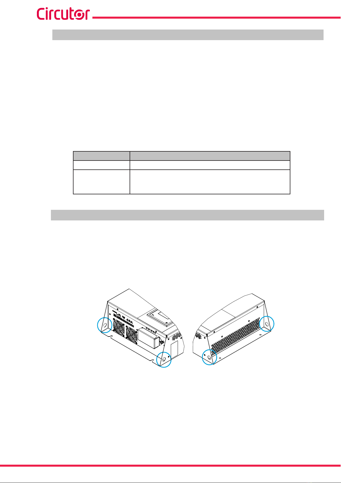
3�4�1�- WALL-TYPE SVGm
The Wall-type SVGm has a number of holes on the top and bottom of the device, Figure 4,to
facilitate transport and installation of the device.
These holes can be used as attachment points for external manipulation tools, or a bar (not
included) can be passed through them to improve transport and installation of the device.
Figure 4: Holes to facilitate transport and installation�
Thedevicemustbexedverticallytoawallorsupport.
Use4xingscrewswithadiameterof8 mm, suitable for the chosen wall or support.

17
Instruction Manual
SVGm
300
500
65
65
15
15
Fixing screws
Fixing screws
Figure 5: Installation Wall-type SVGm�
Use 4M8 xingscrews.
The ventilation grilles must not obstructed or covered at any time.
3�4�2�- RACK-TYPE SVGm
The Rack-type SVGm should be installed in a 19” rack cabinet.
The height of the device is equivalent to 9U. (U is the rack unit, 1U = 4.445 cm)
You can install more than one SVGm in a single cabinet.
Follow these steps to install it inside the cabinet:
1�- Extend the rack cabinet’s anti-tip feet.
Unlesstherackcabinetissecuredtotheoor,theanti-tipfeethavetobeextend-
edandxedtotheoor,toensuremaximumsafetyduringtheassemblyprocess.
2�- Open or remove the door at the front of the cabinet.
3�- Place the SVGm on the cabinet’s rails or shelves. Make sure that they are suitable for the
weight of the device; use cross braces if necessary.
Do not use front handles to carry the module.
18
SVGm
Instruction Manual
Fit the device with the help of another person.
4�- Fasten the device to the points provided for this purpose. Use 4M6xingscrews.
3�4�3�- CABINET-TYPE SVGm
The Cabinet-type SVGm models are free-standing cabinets with 4 bearing supports on the
oor.
The mounting surface must be solid, support the device’s weight and be level.
Thecabinetmustnever be welded to theoor using arcwelding, asthis may
destroy the electronic components.
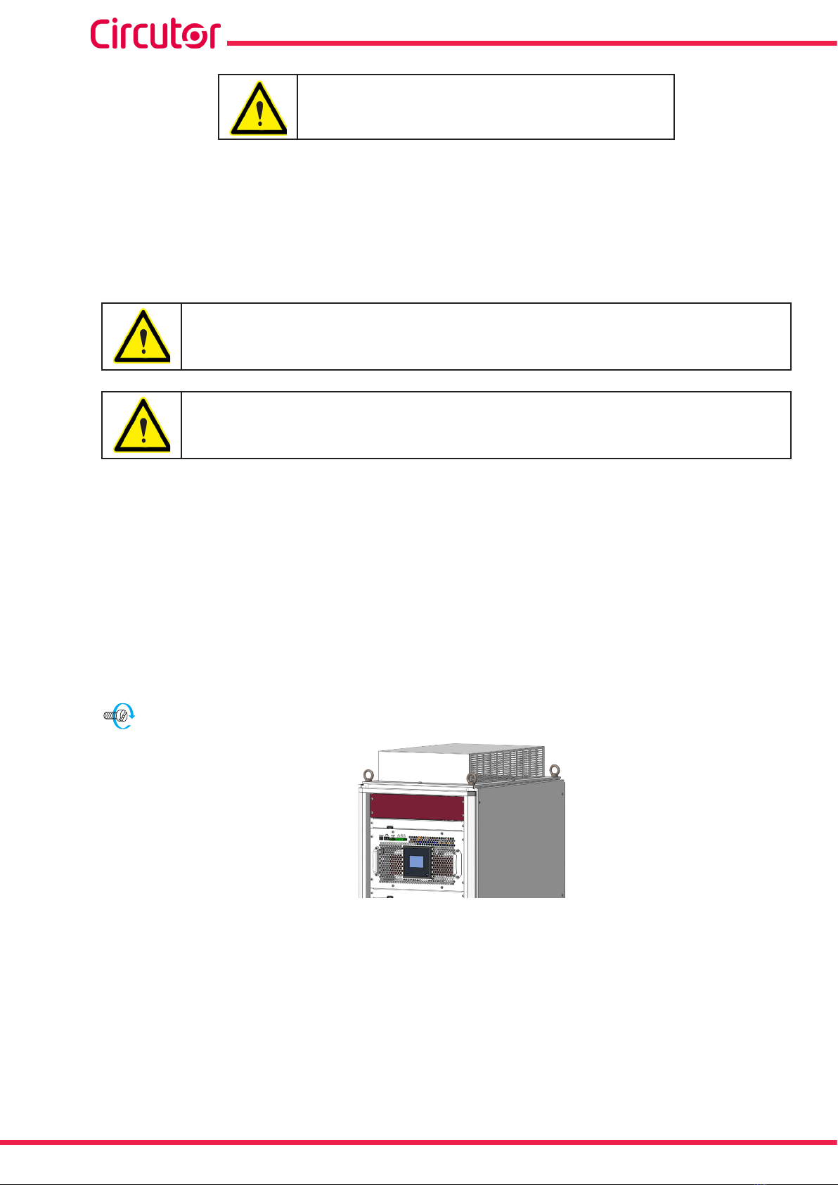
The device’s top panel is part of the ventilation system. The top panel is inverted to make it
easier to transport.
It must be placed in the correct position to enable the device to operate properly. To do this:
1�- Remove the transport rings.
2�- Remove the top panel from the top of the cabinet.
3�- Rotate the top panel. The non-slotted part goes at the front of the cabinet.
4�- Install the transport rings with rubber washers supplied.
20 Nm
Figure 6: Top panel of an SVGm cabinet�
19
Instruction Manual
SVGm
3.5.- CONNECTION
Wall and Rack type SVGm models:
Use cables of a cross-section suitable for the rated current of the static gener-
ator and that comply with the standards of the country in which they are being
installed.
The earth conductor must have at least the same cross-section as the phase
conductors. If the phase conductors exceed 16 mm2, the earth conductor will be
at least 16 mm2. If the phase conductors exceed 32 mm2, the earth conductor can
be the half of the cross-section of the phase conductors
For 100 kvar models (SVGm-xxx-100M and SVGm-xxx-100R), under certain
circumstances, the contact current may exceed 3.5 mA ~.
The recommended minimum cross-sections are:
SVGm-xxx-030M : 16 mm2
SVGm-xxx-060M : 35 mm2
SVGm-xxx-100R and SVGm-xxx-100M : 70 mm2
Neutral conductor cross-section must suit the expected neutral current and must
be selected according to the external protection devices.
Cabinet type SVGm models:
For the cabinet’s power supply, a cable with a cross-section suitable for the max-
imumcurrentthatcanowthroughthedevicemustbeused.Althoughthedevice
is composed of 100 kvar modules, to make installation easier, the modules are
already wired, and the user only has to take into account the device’s total capac-
ity. The recommended minimum cross-sections are:
SVGm-xxx-100C : 70 mm2
SVGm-xxx-200C : 70 mm2 (x2)
SVGm-xxx-300C : 150 mm2 (x2)
SVGm-xxx-400C : 240 mm2 (x2)
Neutral conductor cross-section must suit the expected neutral current and must
be selected according to the external protection devices.
Ensure that the SVGm is earthed correctly to prevent the risk of electric shock.
To measure the current, class 0�2S transformers of the TC or TCH series are
recommended.
The use of transformers with ratios close to the current to be measured is recom-
mended.
The correct connection of the current transformers is vital for the SVGm static
generators to operate properly. If the phases L1, L2 and L3 are switched in the
secondary, the static generator will not work properly.

20
SVGm
Instruction Manual
The SVGm devices have built-in fuse overcurrent protection.
Install external protection according to the type of installation, the facility’s maxi-
mum short-circuit current, the maximum fuse current, and the regulations in force
at the place of installation.
If local regulations require the use of earth leakage protection devices, only DC
sensitive RCD (RCD type B) should be used with SVGm. Static generators work
internally with DC currents, and, in case of failure, the DC currents may produce
malfunction on type A RCD devices.
Ensure that the installation of the device in your electric distribution system (TN,
VT, IT) complies with current standards.
Check that there is a neutral in the place where three-phase static generator connections are
made with neutral, SVGm-4WF-xxxx.
Do not install various static generators in series one after another in the same
installation, congured to correct the same disturbances. This can produce
an overcompensation of the disturbances, which could cause instability in the
mains (Figura 7)
Figure 7: Do not install various static generators in series�
This manual suits for next models
16
Table of contents
Other Circutor Inverter manuals


Popular Inverter manuals by other brands


Aksa
Aksa ALP 8 Installation & operation manual

Generac Power Systems
Generac Power Systems 05176-0 Installation and owner's manual

Growatt
Growatt SPF 2000TL user manual

SunSynk
SunSynk SYNK-8K-SG04LP3 Installer manual

SOLIS
SOLIS S5 Series Installation and operation manual

STERNO HOME
STERNO HOME GL43785 instructions