Circutor CirPower Hyb 4k-48 User manual
INSTRUCTION MANUAL
(M053B01-03-17A)
Hybrid inverter
CirPower Hyb 4k-48

2
CirPower Hyb 4k-48
Instruction Manual
SAFETY PRECAUTIONS
DISCLAIMER
CIRCUTOR, SA
CIRCUTOR, SA
DANGER
ATTENTION
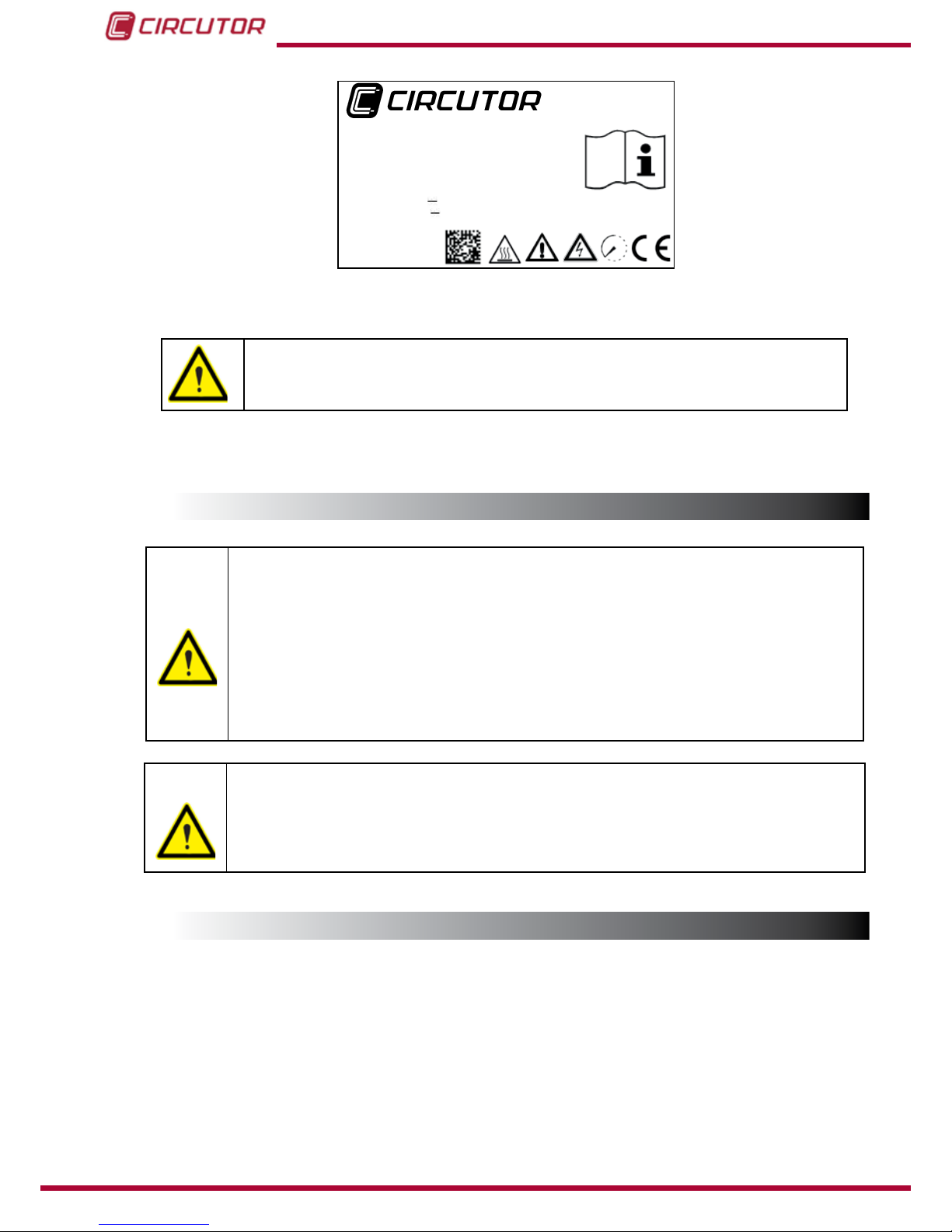
If you must handle the unit for its installation, start-up or maintenance, the following
should be taken into consideration:
Refer to the instruction manual before using the unit
3
Instruction Manual
CirPower Hyb 4k-48

CONTENTS
SAFETY PRECAUTIONS ......................................................................................................................................3
DISCLAIMER .........................................................................................................................................................3
CONTENTS............................................................................................................................................................4
REVISION LOG......................................................................................................................................................6
1.- VERIFICATION UPON RECEPTION................................................................................................................ 7
1.1.- PROTOCOLO DE RECEPCIÓN................................................................................................................ 7
1.2.- TRANSPORT AND HANDLING ............................................................................................................... 8
1.3.- STORAGE.................................................................................................................................................. 8
2.- PRODUCT DESCRIPTION................................................................................................................................9
3.- DEVICE INSTALLATION................................................................................................................................. 10
3.1.- PREVIOUS RECOMMENDATIONS ........................................................................................................ 10
3.2.-LOCATION................................................................................................................................................ 11
3.3.- INSTALLATION ....................................................................................................................................... 12
4.- SAFETY ...........................................................................................................................................................14
4.1.- SAFETY PRECAUTIONS........................................................................................................................ 14
4.2.- PROTECTION ELEMENTS EXTERNAL TO THE CirPower Hyb.......................................................... 15
4.2.1 OVERCURRENT CIRCUIT BREAKER ............................................................................................. 15
4.2.2 RESIDUAL CURRENT CIRCUIT BREAKER .................................................................................... 16
4.3.- PROTECTION ELEMENTS INCLUDED IN THE CirPower Hyb ............................................................ 16
5.- CONNECTIONS...............................................................................................................................................17
5.1.- ELECTRICAL CONNECTIONS............................................................................................................... 17
5.2.- CONNECTION DIAGRAM....................................................................................................................... 18
5.3.- GRID CONNECTION ............................................................................................................................... 18
5.4.- AC OUTPUT CONNECTION ................................................................................................................... 20
5.5.- BATTERY CONNECTION........................................................................................................................ 21
5.6.- SOLAR PANEL CONNECTION............................................................................................................... 23
5.6.1 SOLAR PANEL ARRAY SIZING........................................................................................................ 23
5.6.2 SOLAR PANEL ARRAY CONNECTION ........................................................................................... 24
5.7.- INVERTER AND SOLAR PANELS EARTH GROUNDING.................................................................... 26
5.8.- RS-485 CONNECTION............................................................................................................................ 26
5.9.- ETHERNET CABLE CONNECTION ....................................................................................................... 29
6.- COMMISSIONING ..........................................................................................................................................31
6.1.- COMMISSIONING ................................................................................................................................... 31
6.2.- START-UP PROCEDURE........................................................................................................................ 32
7.- OPERATION ...................................................................................................................................................46
7.1.- DEFINITIONS .......................................................................................................................................... 47
7.1.1.- MINIMUM/MAXIMUM START VOLTAGE, AND MINIMUM STOP CURRENT................................ 47
7.1.2.- VOLTAGE AND FREQUENCY VALUES TO CONNECT TO THE GRID........................................ 47
7.1.3.- MEAN AC GRID VALUE.................................................................................................................. 47
7.1.4.- MPPT (Maximum power point tracking)....................................................................................... 47
7.1.5.- ANTI-ISLANDING PROTECTION ................................................................................................... 47
7.1.6.- RCMU CALIBRATION (Residual Current Monitor Unit) .............................................................. 48
7.1.7.- BATTERY MANAGEMENT (BMS).................................................................................................. 48
7.1.8.- STANDBY MODES.......................................................................................................................... 51
7.2.- OPERATING PRINCIPLE........................................................................................................................ 55
7.2.1.- ENERGY MANAGEMENT STRATEGIES....................................................................................... 55
7.3.- PARALLEL CONNECTIONS................................................................................................................... 64
7.4.- DISPLAY ................................................................................................................................................. 66
7.4.1.- UPPER AREA.................................................................................................................................. 66
7.4.2.- CENTRAL AREA............................................................................................................................. 67
7.4.3.- LOWER AREA................................................................................................................................. 67
8.- DISPLAY .........................................................................................................................................................68
8.1.- MAIN SCREEN ................................................................................................................................69
8.1.1.- INVERTER STATE........................................................................................................................... 69
8.1.2.- KEYS , , ............................................................................................................... 70
8.2.- GRAPH REGISTER ......................................................................................................................... 71
8.2.1.- DAILY GENERATED ENERGY REGISTER.................................................................................... 71
4
CirPower Hyb 4k-48
Instruction Manual

8.2.2.- GENERATED POWER REGISTER.................................................................................................72
8.3.-DISPLAY VALUES ...........................................................................................................................72
8.3.1.- INVERTER.......................................................................................................................................72
8.3.2.- BATTERY.........................................................................................................................................74
8.3.3.- USER ...............................................................................................................................................75
8.3.4.- INVERTER INFORMATION.............................................................................................................76
8.4.- ALARMS AND WARNINGS REGISTER .......................................................................................76
8.4.1.- ALARM ............................................................................................................................................76
8.4.2.- WARNINGS .....................................................................................................................................79
9.- SETUP ............................................................................................................................................................83
9.1.- USER INTERFACE SETUP.....................................................................................................................83
9.1.1.- LANGUAGE.....................................................................................................................................83
9.1.2.- CALIBRATE TOUCH SENSOR.......................................................................................................83
9.1.3.- PERCENTAGE POWER GRAPH....................................................................................................84
9.1.4.- SCREEN BRIGHTNESS..................................................................................................................84
9.1.5.- IP .....................................................................................................................................................84
9.1.6.- QR CODE .......................................................................................................................................84
9.2.- BASIC SETUP ..........................................................................................................................................85
9.2.1.- MPPT ...............................................................................................................................................85
9.2.2.-PV .....................................................................................................................................................86
9.2.3.- ETHERNET......................................................................................................................................87
9.2.4.- BAT ..................................................................................................................................................88
9.3.- CHANGE OF STRATEGY .......................................................................................................................90
9.4.- FACTORY RESET ...................................................................................................................................91
10.- COMMUNICATIONS......................................................................................................................................92
10.1.- RS-485 COMMUNICATION...................................................................................................................92
10.1.1.- MODBUS PROTOCOL..................................................................................................................92
10.1.2.- MODBUS MEMORY MAP .............................................................................................................93
10.2.- ETHERNET COMMUNICATIONS .........................................................................................................96
11.- TECHNICAL FEATURES...............................................................................................................................97
12.- MAINTENANCE AND TECHNICAL SERVICE............................................................................................100
13.- GUARANTEE...............................................................................................................................................100
14.- CE CERTIFICATE........................................................................................................................................101
5
Instruction Manual
CirPower Hyb 4k-48

REVISION LOG
Table 1: Revision log.
Date Revision Description
6
CirPower Hyb 4k-48
Instruction Manual
Note: Device images are for illustrative purposes only and may differ from the actual device.

1.- VERIFICATION UPON RECEPTION
Figure 1Table 2
Table 2: Scope of delivery.
Object Description Quantity
CirPower Hyb 1
1
1
F 1
G 1
1
1
1
AB C D F
E
G
Figure 1: Scope of delivery.
Figure 2
7
Instruction Manual
CirPower Hyb 4k-48
CirPower Hyb 4k-48
SN:800300000
E15311
Made in EU (Spain)
FYYSSXXXXXyyyyy
CIRCUTOR SA - Vial Sant Jordi, s/n
0
8232 Viladecavalls (Barcelona) Spain 08232
Battery: 38...60V 80A 4000W -20...50ºC - IP55 - Class I
AC Grid: Input 230 V~ 50Hz 17.4 A
4000W (cosφ=1)/3600W (cosφ=0.9)
AC Load: Output 230V ~ 50Hz 17.4A
PF-0.5...0.5 - 4000W(cosφ=1)/3600W(cosφ=0.9)
PV: 150 ... 700V 20A 4200W
Figure 2: Specications plate.
CIRCUTOR
“1.2.- TRANSPORT
AND HANDLING”
“1.3.- STOR-
AGE”.
58kg
8
CirPower Hyb 4k-48
Instruction Manual

2.- PRODUCT DESCRIPTION
CirPower Hyb
RS-485
Ethernet
Display
9
Instruction Manual
CirPower Hyb 4k-48

3.- DEVICE INSTALLATION
CirPower Hyb
10
CirPower Hyb 4k-48
Instruction Manual

CirPower Hyb
Figure 3: Installation location
CirPower Hyb
“3.3.- INSTALLATION”.
CirPower Hyb
11
Instruction Manual
CirPower Hyb 4k-48

1.-
Figure 4
Table 3: Minimum distances.
MINIMUM DISTANCES
300 mm
600 mm
Figure 4: Minimum distances.
2.-
Figure 5
Figure 5: Fix the wall-mount support.
12
CirPower Hyb 4k-48
Instruction Manual

3.-Figure 6
Figure 6: Hang the device.
Note: Figure 7
Figure 7:Safety lock.
13
Instruction Manual
CirPower Hyb 4k-48

4.- SAFETY
This item denes the safety precautions that must be followed during any operation
done in the device.
Risk of death due to dangerous voltages.
Do not touch any component under voltage in the inverter.
Do not touch DC wirings.
Disconnect the inverter from every supply and wait 5 minutes before doing
any operation.
Risk of death due to dangerous voltages while working on the inverter.
Inverter must work always with door closed.
Do not touch any insulation damaged wire.
Risk of burning due to contact with envelope hot surface.
Risk of death due to dangerous voltages.
Do not connect the grid to the AC Output connector.
14
CirPower Hyb 4k-48
Instruction Manual

Warning, residual current
CirPower Hyb
Warning, damage to the inverter due to electrostatic discharge.
Warning, damage to the door seal due to freezing.
4.2.1 OVERCURRENT CIRCUIT BREAKER
curve B
25A
curve-B25A
15
Instruction Manual
CirPower Hyb 4k-48
4.2.2 RESIDUAL CURRENT CIRCUIT BREAKER
Table 4: Residual current circuit breaker
Connection RCB Type
Grid
CirPower Hyb
EN62109-2
EN62109-2
16
CirPower Hyb 4k-48
Instruction Manual

5.- CONNECTIONS
CirPower Hyb Figure 8
A
B C D E F
G
H
I
J
Figure 8:Terminal connections.
Table 5: Terminal connections.
Description
A
B
C
D
E
F
G
H
I PV+
JPV-
17
Instruction Manual
CirPower Hyb 4k-48

FV+, FV -
Battery - / Batería -
Battery + / Batería +
AC output / Salida CA
AC grid/ Red CA
Figure 9: Connection diagram
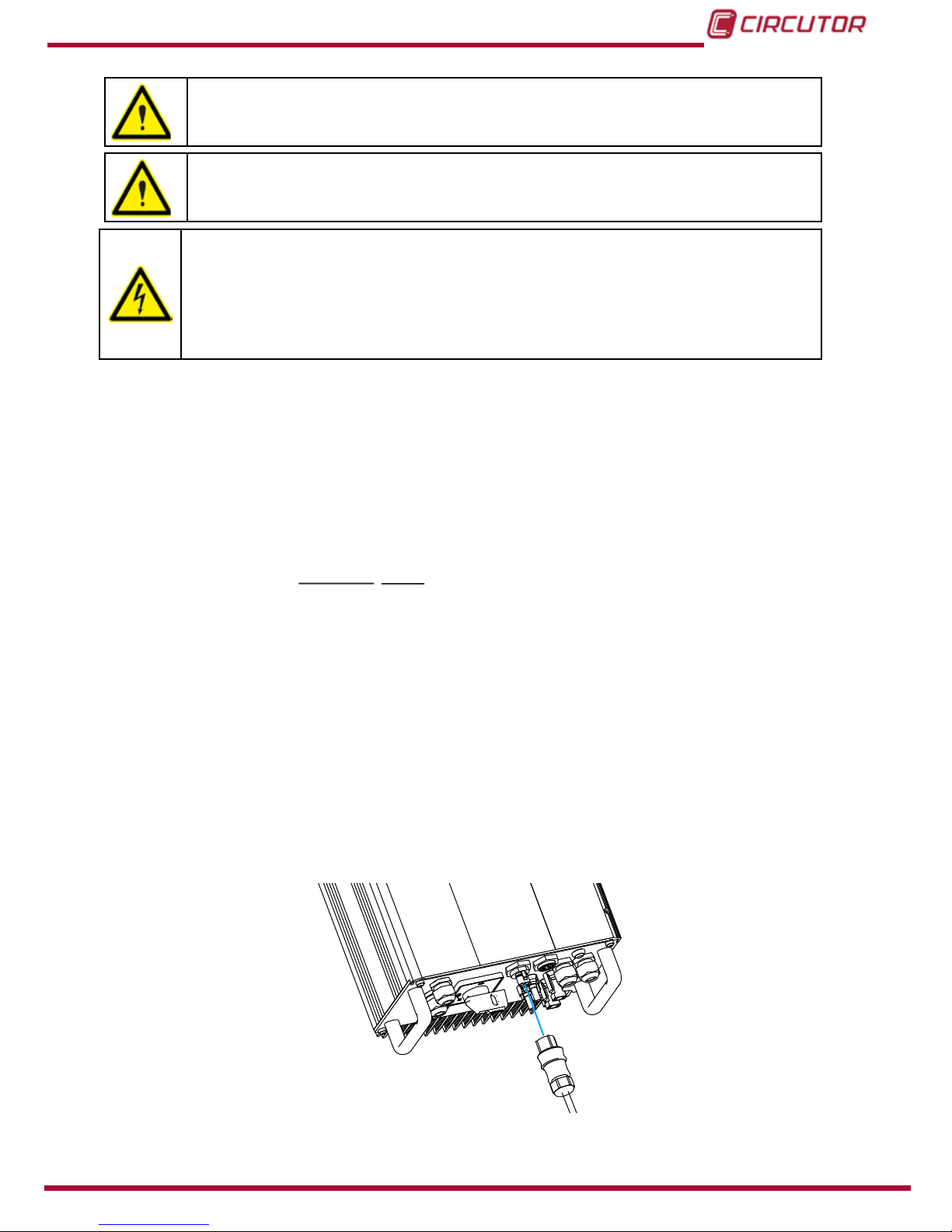
Figure 10: Grid connection.
Before starting the procedure, be sure that the grid connection circuit
breaker is switched off.
Signal and ensure that there is no re-connection by accident.
18
CirPower Hyb 4k-48
Instruction Manual
PV switch
Risk of death due to dangerous voltages.
Do not connect the grid to the AC Output connector.
CirPower Hyb
1.-
EN62109-2
Ω
For the CirPower Hyb VMAX PV: 700V
23.3kΩ
2.-
3.-
4.-
5.-
Screws tightening torque :
Figure 11: Connect the grid cable.
6.-
19
Instruction Manual
CirPower Hyb 4k-48

Figure 12: AC output connection.
Risk of death due to dangerous voltages.
Do not connect the grid to the AC Output connector.
Figure 13: Connect the AC output.
20
CirPower Hyb 4k-48
Instruction Manual
Table of contents
Other Circutor Inverter manuals


Popular Inverter manuals by other brands


BARRON
BARRON EXITRONIX Tucson Micro Series installation instructions

Baumer
Baumer HUBNER TDP 0,2 Series Mounting and operating instructions

electroil
electroil ITTPD11W-RS-BC Operation and Maintenance Handbook

Silicon Solar
Silicon Solar TPS555-1230 instruction manual

Mission Critical
Mission Critical Xantrex Freedom SW-RVC owner's guide

HP
HP 3312A Operating and service manual


