Circutor Bridge LR User manual
INSTRUCTION MANUAL
RS-485 - LoRaTN converter
Bridge LR
(M377B01-03-22A)

2
Bridge LR
Instruction Manual

3
Instruction Manual
Bridge LR
SAFETY PRECAUTIONS
DANGER
Warns of a risk, which could result in personal injury or material damage.
ATTENTION
Indicates that special attention should be paid to a specific point.
Follow the warnings described in this manual with the symbols shown below.
If you must handle the unit for its installation, start-up or maintenance, the following should be
taken into consideration:
Incorrect handling or installation of the device may result in injury to personnel as well as damage to
the device. In particular, handling with voltages applied may result in electric shock, which may cause
death or serious injury to personnel. Defective installation or maintenance may also lead to the risk of
fire.
Read the manual carefully prior to connecting the device. Follow all installation and maintenance in-
structions throughout the device’s working life. Pay special attention to the installation standards of
the National Electrical Code.
Refer to the instruction manual before using the device
In this manual, if the instructions marked with this symbol are not respected or carried out correctly, it can result
in injury or damage to the device and/or installations.
CIRCUTOR S.A.U. reserves the right to modify features or the product manual without prior notification.
DISCLAIMER
CIRCUTOR S.A.U. reserves the right to make modifications to the device or the unit specifications set
out in this instruction manual without prior notice.
CIRCUTOR S.A.U. on its web site, supplies its customers with the latest versions of the device specifi-
cations and the most updated manuals.
www.circutor.com
CIRCUTOR S.A.U. recommends using the original cables and accessories that are sup-
plied with the device.

4
Bridge LR
Instruction Manual
CONTENTS
SAFETY PRECAUTIONS .........................................................................................................................................................3
DISCLAIMER ..........................................................................................................................................................................3
CONTENTS.............................................................................................................................................................................4
REVISION LOG .......................................................................................................................................................................5
SYMBOLS...............................................................................................................................................................................5
1. VERIFICATIONS UPON RECEPTION..................................................................................................................................6
2. PRODUCT DESCRIPTION .................................................................................................................................................6
3. INSTALLING THE DEVICE.................................................................................................................................................7
3.1.- PRELIMINARY RECOMMENDATIONS ........................................................................................................................7
3.2.- INSTALLATION ........................................................................................................................................................ 8
3.3.- TERMINALS OF THE DEVICE ................................................................................................................................... 8
3.3.1.- MODEL Bridge LR PSAC ................................................................................................................................... 8
3.3.2.- MODEL Bridge LR PSDC................................................................................................................................... 8
4. OPERATION ..................................................................................................................................................................10
4.1.- LEDs.......................................................................................................................................................................10
4.2.- PUSH-BUTTON ......................................................................................................................................................10
4.3.- OPERATING PRINCIPLE...........................................................................................................................................11
4.4.- LoRaTM COMMUNICATION PARAMETERS ................................................................................................................11
4.5.- LoRaTM COMMUNICATION RULES .......................................................................................................................... 13
4.6.- LoRaTM TRANSMISSION CYCLE .............................................................................................................................. 14
4.7.- RS-485 COMMUNICATION .....................................................................................................................................15
5. CONFIGURATION SOFTWARE........................................................................................................................................ 17
6. TECHNICAL FEATURES................................................................................................................................................. 20
7. MAINTENANCE AND TECHNICAL SERVICE....................................................................................................................22
8. WARRANTY ...................................................................................................................................................................22
9. UE DECLARATION OF CONFORMITY .............................................................................................................................23
5
Instruction Manual
Bridge LR
REVISION LOG
Table 1:Revision log.
Date Revision Description
10/22 M377B01-03-22A Initial Version
Note: The images of the devices are for illustrative purposes only and may differ from the original device.
SYMBOLS
Table 2: Symbols.
Symbol Description
Compliant with the relevant European standards.
Device covered by European directive 2012/19/EC. At the end of its useful
life, do not leave the unit in a household waste container. Follow local regulations
on electronic equipment recycling.
DC current
~AC current
6
Bridge LR
Instruction Manual
1.- VERIFICATIONS UPON RECEPTION
The following must be checked upon reception of the device:
a) The device has been supplied according to the specifications in your order.
b) The device has not been damaged during transport.
c) Perform an external visual inspection of the device before connecting it.
d) Check that it has been supplied with the following:
- An installation guide
Immediately contact the carrier and/or CIRCUTOR's after-sales service if you
detect any problem in the device upon reception.
2.- PRODUCT DESCRIPTION
Bridge LR is a gateway that makes the conversion between the RS-485 physical environment and the
LoRaTM long-range wireless network.
The device is fully configurable using a configuration software.
CIRCUTOR has 2 models:
Bridge LR PSAC, AC powered.
Bridge LR PSDC, DC.
The device has:
- 3 indicating LEDs to check transmission status.
- 1 push-button
7
Instruction Manual
Bridge LR
3.- INSTALLING THE DEVICE
3.1.- PRELIMINARY RECOMMENDATIONS
In order to use the device safely, it is critical that individuals who handle it follow the
safety measures set out in the standards of the country where it is being used, use the
personal protective equipment necessary (rubber gloves, face protection and approved
flame-resistant clothing) to prevent injuries due to electric shock or electric arc due
to exposure to current-carrying conductors and pay attention to the various warnings
indicated in this instruction manual.
The Bridge LR must be installed by authorised and qualified staff.
The power supply must be disconnected before handling, altering the connections or replacing the
device. Handling the device while it is connected is hazardous to people nearby.
It is essential to keep the cables in a perfect condition to avoid accidents, personal injury and damage
to installations.
Limit the operation of the device to measuring the specified current or voltage values.
The manufacturer of the device shall not be held responsible for any damage resulting from the user
or installation company failing to observe the warnings and/or recommendations indicated in this
manual nor for any damage resulting from the use of non-original products or accessories or those
from other brands.
Do not use the device to take measurements if you detect an anomaly or malfunction.
The device must be disconnected from its power supply sources (power supply and
measurement) before undertaking any installation, repair or handling operations on
the device’s connections. Contact the after-sales service if you suspect that there is an
operational fault in the device.

8
Bridge LR
Instruction Manual
3.2.- INSTALLATION
While the device is connected, the terminals, opening the cover or removing elements
may expose hazardous live parts. The device must not be used until the installation
process is complete.
Bridge LR has been designed for DIN rail assembly.
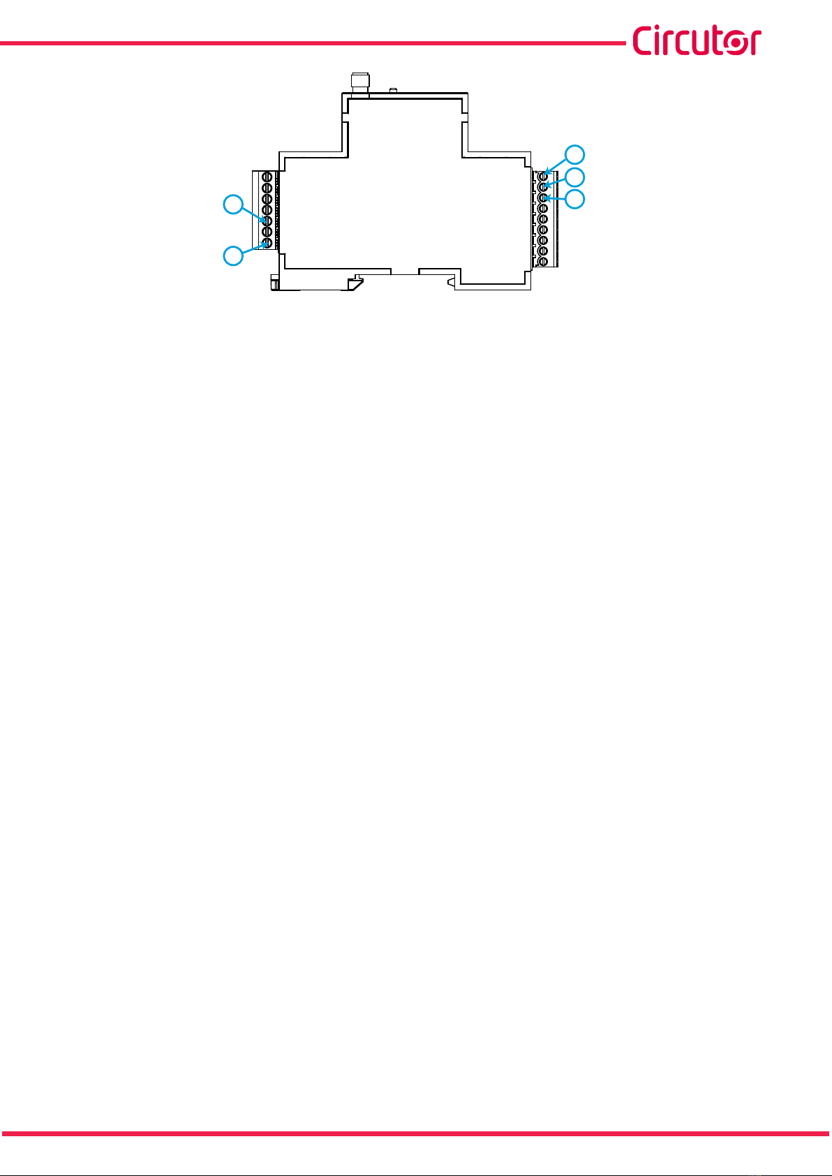
3.3.- TERMINALS OF THE DEVICE
3.3.1.- MODEL Bridge LR PSAC
Table 3:List of terminals of Bridge LR PSAC.
Terminals of the device
1: L, Power supply 4: B(-), RS-485 port
2: N, Power supply 5: GND, RS-485 port
3: A(+), RS-485 port
L
N
A+
B-
GND
1
2
3
4
5
Figure 1:Bridge LR PSAC terminals.
3.3.2.- MODEL Bridge LR PSDC
Table 4:List of terminals of Bridge LR PSDC.
Terminals of the device
1: V-, Power supply 4: B(-), RS-485 port
2: V+, Power supply 5: GND, RS-485 port
3: A(+), RS-485 port
9
Instruction Manual
Bridge LR
V-
V+
A+
B-
GND
1
2
3
4
5
Figure 2:Bridge LR PSDC terminals.
10
Bridge LR
Instruction Manual
4.- OPERATION
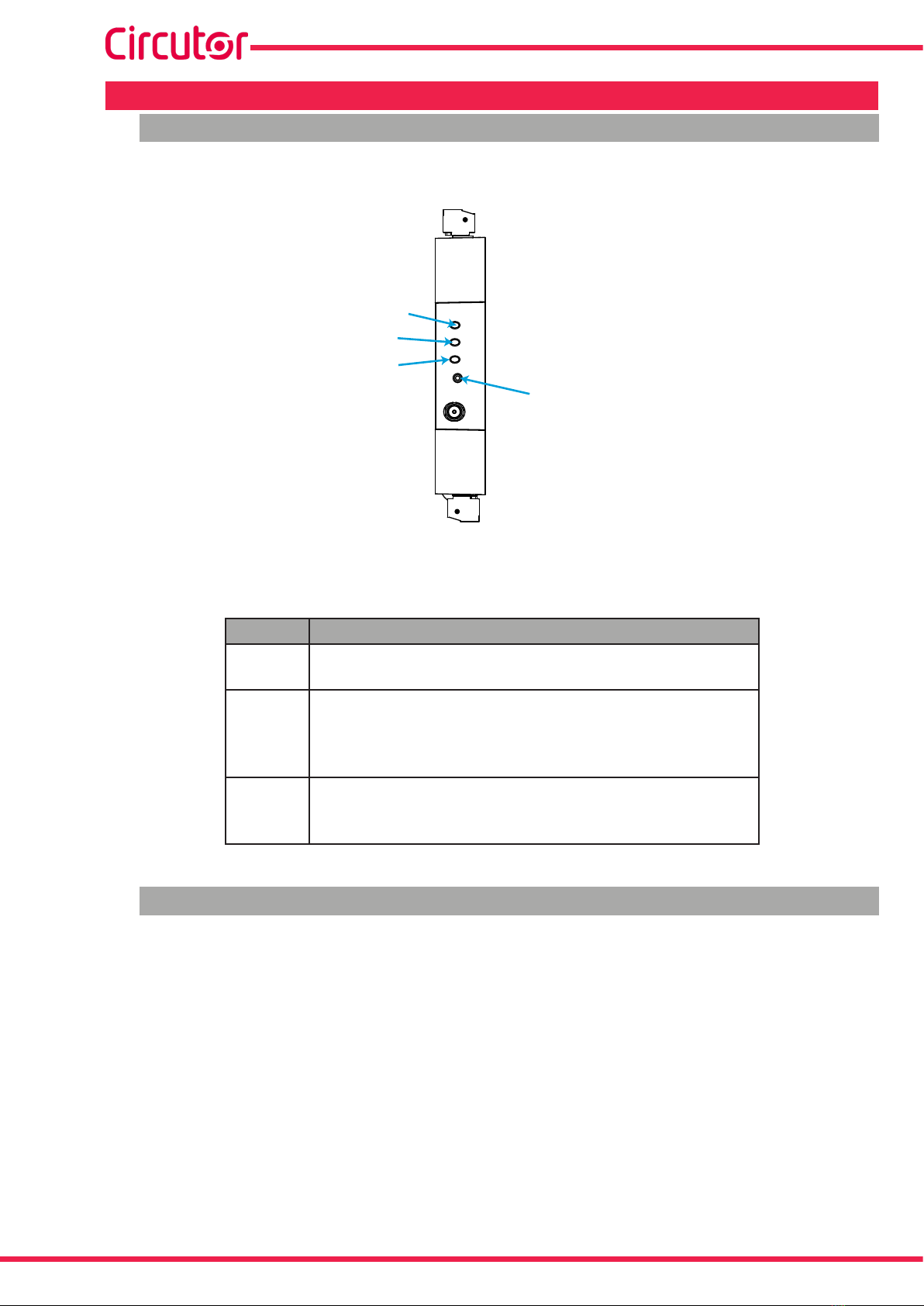
4.1.- LEDs
The Bridge LR has 3 LEDs to indicate transmission status, Table 5.
COM
RF
ON
RST
COM
RF
ON
Push-Button
Figure 3: LEDs.
Table 5: LEDs.
LEDs State
ON Power supply
Green: Activity
RF
LoRaTM communications
Red slow flashing : data transmission
Green fast flashing : data reception
Blue : Silence/Waiting time (only in Master mode)
COM
RS-485 communications
Red fast flashing : data transmission
Green fast flashing : data reception
4.2.- PUSH-BUTTON
The Bridge LR has 1 push-button (RST or RESET) to reset the device; see Figure 3.

11
Instruction Manual
Bridge LR
4.3.- OPERATING PRINCIPLE
The Bridge LR is a gateway for converting data between the RS-485 physical environment and the
LoRaTM long-range wireless network.
These devices can be used to connect multiple RS-485 buses to a master, considerably reducing the
cabling required. This can be done by simply connecting an Bridge LR configured as the Master to the
RS-485 master, and an LR1RS + configured as the Slave to each of the buses to be connected; see
Figure 4.
...
...
...
...
...
...
RS-485
Bus 1 Bus 2 Bus 3
Bus 1 RS-485
Bus 2 RS-485
Bus 3 RS-485
LoRa™LoRa™LoRa™
LoRa™
1
2
32
1
2222 2
1
111
32 32 32 32 32
Figure 4: Example of LoRaTM connection.
There can be up to 32 end devices on each communications bus.
Communication between the Bridge LR master and slave devices is fully transparent, therefore
allowing straightforward installation by simply controlling transmission time between messages and
the time-out period from the application’s master.
4.4.- LoRaTM COMMUNICATION PARAMETERS
The device is connected to LoRaTM radio technology for private networks.
Bridge LR devices can only be used in private networks and cannot be connected to
LoRaWAN networks.
In Europe the frequency for LoRaTM communications is the 868 MHz ISM free band, allowing configu-
ration of up to 9 different channels between 865.1 MHz (channel 0) and 869.85 MHz (channel 9). The
default frequency is 869.525 (channel 7).
The channels have different settings of working time and silence time depending on restrictions of
each frequency. The Table 6 shows the Duty cycle of each frequency channel which is the percentage
of time that it’s allowed to transmit in each channel. The smaller the duty cycle is, more restrictive the
transmission period is. It’s recommended to use channels with bigger duty cycle for applications that
12
Bridge LR
Instruction Manual
require a faster data refresh time.
Table 6: Duty cycle.
Channel Frequency Duty cycle
0 865.1 MHz 1 %
1 865.2 MHz 1 %
2 865.6 MHz 1 %
3 868.5 MHz 1 %
4 868.3 MHz 1 %
5 868.85 MHz 0.10 %
6 868.95 MHz 0.10 %
7 869.525 MHz 10 %
8 869.85 MHz 1 %
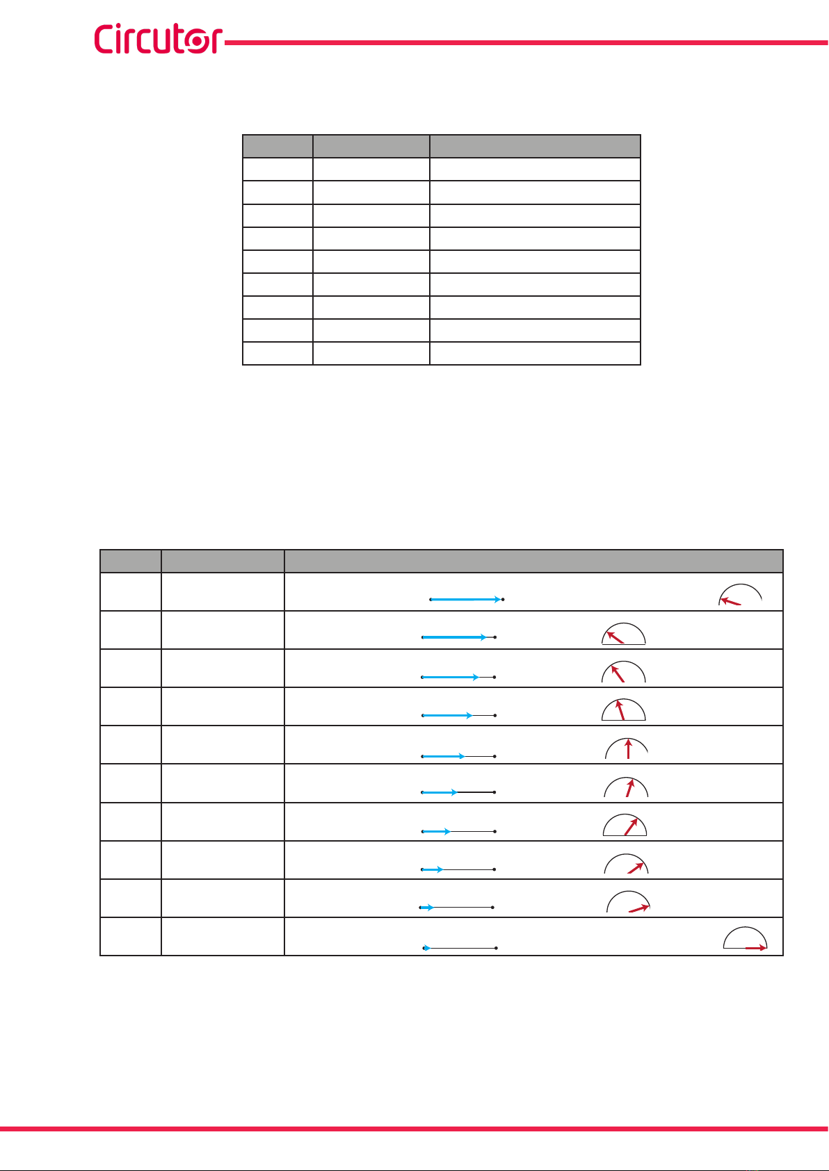
The device has 10 transmission and reception modes (Table 7) in order to select speeds between 300
bps and 21875 bps, with the option of increasing communication speed by trading off transmission
signal range.
A period of silence during which the device cannot transmit has been set in order to respect the spec-
tral limitation, in accordance with the transmission mode selected in the master; during this time, the
RF LED lights up in blue and the device returns “Occupied” through the serial channel.
Table 7:Transmission and Reception modes.
Mode Bits per second Description
0 292.97 bps Maximum distance: (Max: 15 km) , Minimum bit rate:
1 585.94 bps (Max: 7.50 km),
2 976.56 bps (Max: 4.50 km),
3 1171.88 bps (Max: 3.75 km),
4 1953.13 bps (Max: 2.25 km),
5 2148.44 bps (Max: 2.05 km),
6 3515.63 bps (Max: 1.25 km),
7 7031.25 bps (Max: 0.63 km),
8 12500 bps (Max: 0.35 km),,
9 21875 bps Minimum distance: (Max: 0.20 km), Maximum bit rate:
13
Instruction Manual
Bridge LR
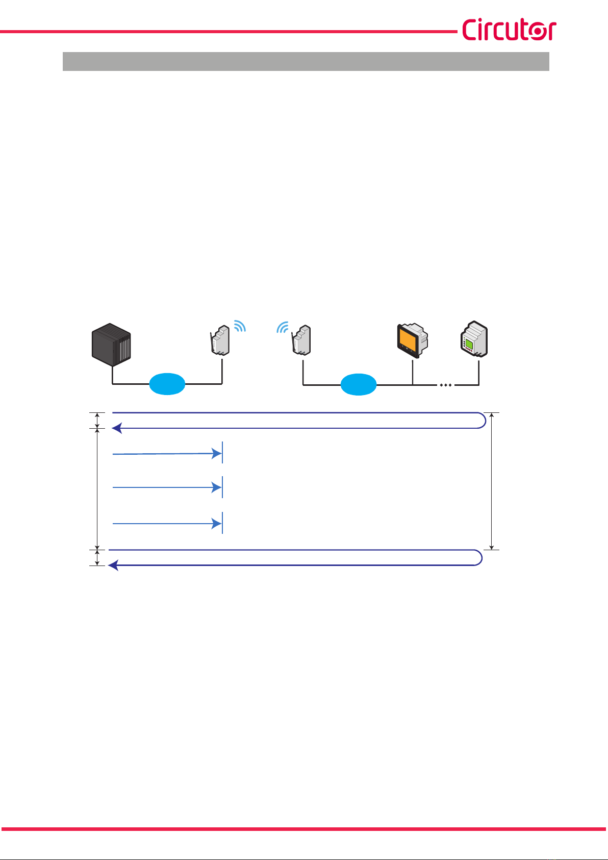
4.5.- LoRaTM COMMUNICATION RULES
In a LoRa™ installation, the following times must be taken into account:
Transmission time: It’s the time it takes for a data submission to go out of the Modbus Master, get
the data from the Modbus slave and return to the Modbus Master (a complete communication cycle).
On LoRa™ communications, it could take from 0,5 to 10 seconds, depending on Bridge LR configu-
ration.
Silence time: According on the configuration of Mode, Frequency and Transmission time, Bridge LR
Master fix a silence time. During this time, all RS-485 communication through the LoRa™ network
are blocked. If the Modbus Master continues sending data requests, it will receive timeout answers.
Time between transmissions: From the point of view of Modbus Master, it’s the time between RS-
485 or Ethernet requests. Basically, the sending cadence.
LoRa™
RS-485
Modbus
Master
Bridge LR
Master
Bridge LR
Slave
Modbus
Slave
Modbus
Slave
RS-485
Transmission
time
Transmission
time
Time of
silence
Time between
transmissions
Figure 5:Times in LoRa™ communications.
Based on these times, we establish 2 communication rules that must be applied at the Modbus Master.
Rule #1: Is completely mandatory in order to establish communication with the Modbus slaves through
a Bridge LR network:
Timeout RX Master Modbus > Transmission time
Rule #2: It allows avoiding having timeouts in the communication bus of the Modbus Master since the
Time between transmissions becomes greater than the Transmission Time required plus the Silence
Time that the Bridge LR Master (RF LED in blue):
Time between transmissions = Transmission time + Silence time

14
Bridge LR
Instruction Manual
4.6.- LoRaTM TRANSMISSION CYCLE
In order to reach a wireless communication between the Modbus master and the Modbus slaves (via
Bridge LR), timing rules must be configured on the Modbus master responsible to communicate with
the devices.
In order to facilitate the configuration of the Modbus masters, Table 8 and Table 9 show a guide to the
Transmission Times and Silence Times generated in two common scenarios, such as the request of 1
and 2 Modbus registers.
The Transmission time must be configured as timeout; and the Total time must be configured as Time
between transmissions in the Modbus Master. The first one is totally mandatory for the application to
work, while the second one will allow us to control the cadence of questions to be able to make se-
quential and orderly requests, and thus avoid having Modbus communication errors during the silence
time of the Bridge LR Master.
1.- Transmission of 1 Modbus register (16 bits)
Table 8:Transmission of 1 Modbus register (16 bits).
LoRa™
Mode
Transmission
time
Silence
time
Total
time
0 4 s 8 s 12 s
1 3 s 3 s 6 s
2 2 s 3 s 5 s
3 2 s 2 s 4 s
4 1 s 2 s 3 s
5 1 s 1 s 2 s
6 1 s 1 s 2 s
7 1 s 1 s 2 s
8 0.402 s 1 s 1.402 s
9 ≈ 0 ≈ 0 0.126 s
2.- Transmission of 2 Modbus register (32 bits)
Table 9:Transmission of 2 Modbus register (32 bits).
LoRa™
Mode
Transmission
time
Silence
time
Total
time
0 4 s 16 s 18 s
1 3 s 6 s 9 s
2 3 s 3 s 6 s
3 2 s 3 s 5 s
4 2 s 2 s 4 s
5 1 s 2 s 3 s
6 1 s 1 s 2 s
7 1 s 1 s 2 s
8 0.804 s 1 s 1.804 s
9 ≈ 0 ≈ 0 0.196 s
15
Instruction Manual
Bridge LR
4.7.- RS-485 COMMUNICATION
The Bridge LR have one RS-485 communications port, with MODBUS RTU ®, for reading and writing
the device parameters.
In the Modbus protocol uses the RTU (Remote Terminal Unit) mode.
The Modbus functions implemented in the device are as follows:
Function 0x03: Read holding registers.
Function 0x06: Preset single register.
Function 0x10: Preset multiple registers.
Note: All the addresses of Modbus memory are in Hexadecimal.
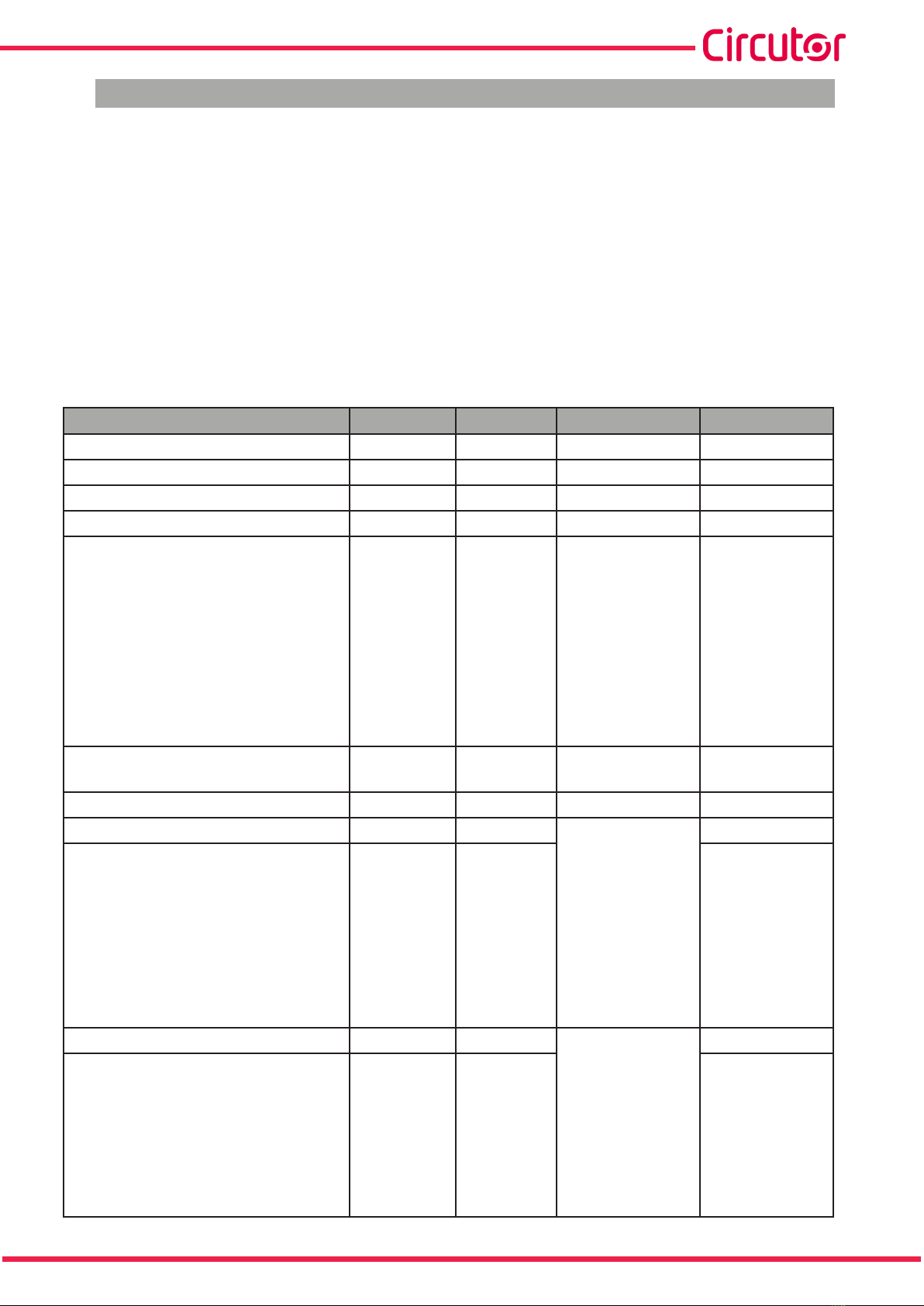
Table 10: Modbus memory map.
Parameter Adress Function Values Default values
Serial number 00 - 03 03 - -
Software version 04 - 05 03 - -
Hardware version 07 03 - -
Peripheral number 0E - 0F 03, 06, 10 - 1
RS-485 communication 10 - 11 03, 06, 10
0: 9600, 8, N, 1
1: 19200, 8, N, 1
2: 38400, 8, N, 1
3: 57600, 8, N, 1
4: 115200, 8, N, 1
5: 9600, 8, E, 1
6: 19200, 8, E, 1
7: 9600, 8, N, 2
8: 19200, 8, N, 2
13: 38400, 8, N, 2
9600, 8, N, 1
Operating mode 12 - 13 03, 06, 10 0: Slave
1: Master 0
Silence time (only Master) 1E - 1F 03 ms -
LoRaTM mode UpLink 50 - 51 03, 06, 10 0: 292.97 bps
1: 585.94 bps
2: 976.56 bps
3: 1171.88 bps
4: 1953.13 bps
5: 2148.44 bps
6: 3515.63 bps
7: 7031.25 bps
8: 12500 bps
9: 21875 bps
0
LoRaTM mode DownLink 52 - 53 03, 06, 10 0
LoRaTM frequency UpLink 54 - 55 03, 06, 10 0: 865.1 MHz
1: 865.2 MHz
2: 865.6 MHz
3: 868.5 MHz
4: 868.3 MHz
5: 868.85 MHz
6: 868.95 MHz
7: 869.525 MHz
8: 869.85 MHz
7
LoRaTM frequency DownLink 56 - 57 03, 06, 10 7

16
Bridge LR
Instruction Manual
Table 10 (Continuation): Modbus memory map.
Parameter Adress Function Values Default values
Radio synchronization ID 58 - 59 03, 06, 10
0: No subnet-
works
Other: Subnet-
work ID
-
Radio signal strength(1) 1004 04
MSB: RSSI (nega-
tive dBm)
LSB: SNR (2)
-
(1) Parameter available for firmware version 11.0 or later.
(2) If 0 < SNR < 15, Positive. If SNR > 15, Subtract 0xFF and process as Negative.
If the peripheral address assigned to a device is forgotten, the default value can be retrieved as follows:
1.- Press the RST or RESET(Bridge LR PSDC model) push-button for 10 seconds.
2.- All the LEDs flash and the device returns to its factory settings when the push-button is released.
17
Instruction Manual
Bridge LR
5.- CONFIGURATION SOFTWARE
The Bridge LR is configured using PC software, which can be downloaded from the website (www.
circutor.com).
Proceed as follows to start configuration:
1.- Connect the Bridge LR to the computer via a USB - RS-485 gateway.
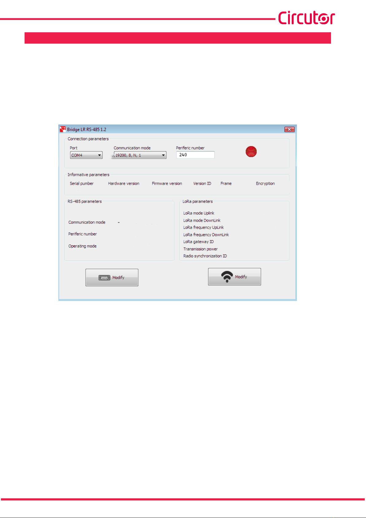
2.- Run the Configuration software on the computer, which will display the screen in Figure 6.
Figure 6: Configuration software: Home screen.
3.- In the Connection parameters section, select:
The Communications Port assigned by the PC.
The Communication mode.
The Peripheral number.
4.- Once the device is communicating with the PC, the connection icon turns green, displaying the In-
formative parameters and the default RS-485 and LoRaTN parameters (Figure 7).

18
Bridge LR
Instruction Manual
Figure 7: Configuration software: Device connected.
5.- Press the Modify button to change the RS-485 communication parameters. The win-
dow shown in Figure 8 will be displayed.
Figure 8:Configuration software: RS-485 parameters.
The following items can be modified in this window:
The Communication mode.
The Periferic number.
The Device’s Operating mode, i.e. whether the Bridge LR will work as the installation’s Mas-
ter or Slave.
Note: Only the device that connects to the RS-485 master can be configured as the Master in
the installation.
Press to send the changes to the device. The changes are applied automatically.
240
19
Instruction Manual
Bridge LR
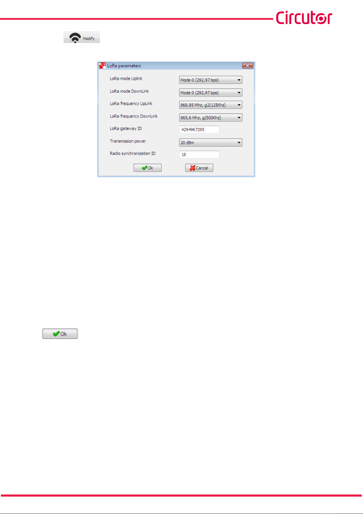
6.- Press the button to change the LoRaTM communication parameters.The window shown
in Figure 9 will be displayed.
Figure 9:Configuration software:LoRaTM. parameters.
The following items can be modified in this window:
LoRa mode Uplink.
LoRa mode DownLink.
LoRa frequency Uplink.
LoRa frequency DownLink.
LoRa gateway ID.
Transmission power.
Radio synchronization ID.
For basic configuration, simply ensure that the Radio synchronization ID parameter has the same val-
ue in all devices, both in the installation’s Master and in all the Slaves to be communicated.
The other parameters should only be altered in the event of radio communication problems.
Press to send the changes to the device. The changes are applied automatically.

20
Bridge LR
Instruction Manual
6.- TECHNICAL FEATURES
AC Power supply: Bridge LR PSAC
Rated voltage 110 ... 264 V ~
Frequency 47 ... 63 Hz
Maximum Consumption 2.5 ... 4.5 VA
Installation category CAT III 300V
DC Power supply: Bridge LR PSDC
Rated voltage 9 ... 36 V
Maximum Consumption 1 W
Installation category CAT III 300V
Serial interface
Type RS-485 3 wire
Baud rate 9600 - 19200 - 38400 - 57600 - 115200 bps
Data bits 8
Parity without - even
Stop bits 1 - 2
Wireless interface
Technology LoRaTM
Frequency (Europe) 868 MHz ISN band (9 channels)
Standard range 1 km indoor
20 km exterior with direct vision
User interface
LEDs 3 LEDs
Button 1
Environmental features
Operating temperature -10ºC ... +60ºC
Relative humidity 5 ... 95 %
Maximum altitude 2000 m
Protection degree IP20
Mechanical features
Dimensions (mm) Figure 10
Weight 90 g.
Enclosure Plastic UL94 - Self-extinguishing V0
Attachment DIN rail
Electrical safety
Protection against electric shock Double insulation class II
Standars
Safety requirements for electrical equipment for measurement, control and laboratory use
-- Part 1: General requirements EN 61010-1
Electromagnetic compatibility (EMC) -- Part 6-2: Generic standards - Immunity for indus-
trial environments EN 61000-6-2
Electromagnetic compatibility (EMC)-- Part 6-4: Generic standards- Emission standard for
industrial environments EN 61000-6-4
This manual suits for next models
4
Table of contents
Other Circutor Media Converter manuals


