Circutor TPC2RS User manual

RS232/485 –TCP/IP converter
TPC2RS
(7 70 029)
Ver. 01A- GB

----------- TCP2RS -------------- User’s manual -------------------- page 2/43
2
1: INTRODUCTION..................................................................................................5
1.1 NETWORK PROTOCOLS ......................................................................................5
1.1.1 Packing Algorithms...................................................................................6
1.1.2 Ethernet (MAC) Address............................................................................6
1.1.4 Port Number..............................................................................................6
2: INSTALLATION...................................................................................................7
2.1 PRODUCT DESCRIPTION .....................................................................................7
2.1.1 Serial Interface..........................................................................................7
2.1.2 Network Interface......................................................................................7
2.1.3 LEDs.........................................................................................................7
2.1.4 Product Information Label.........................................................................8
2.2 INSTALLING THE TCP2RS..................................................................................8
3: GETTING STARTED ...........................................................................................9
3.1 DEFAULT IP ADDRESS .......................................................................................9
3.2 IP ADDRESS CONFIGURATION .......................................................................... 10
3.2.1 Network Port Login (1)..............................................................................10
3.2.2 Network Port Login (2)..............................................................................10
3.2.3 Serial Port Login.....................................................................................11
4: CONFIGURATION.............................................................................................13
4.1 NETWORK CONFIGURATION .............................................................................13
4.1.1 Using a Web Browser..............................................................................13
4.1.2 Using a Telnet Connection.......................................................................14
4.2 SERIAL CONFIGURATION..................................................................................14
4.3 CONFIGURATION PARAMETERS ........................................................................ 14
4.4 SERVER CONFIGURATION.................................................................................16
4.4.1 IP Address...............................................................................................16
4.4.2 Gateway Address..................................................................................... 16
4.4.3 Netmask ..................................................................................................16
4.4.4 Telnet Configuration Password................................................................17
4.5 SERIAL CHANNEL (PORT) CONFIGURATION ...................................................... 17
4.5.1 Baud Rate................................................................................................17
4.5.2 Interface Mode ........................................................................................17
4.5.3 Flow Control........................................................................................... 18
4.5.4 Port Number............................................................................................18
4.5.5 Connect Mode.........................................................................................18
4.5.6 Remote IP Address ..................................................................................21
4.5.7 Remote Port ............................................................................................ 21
4.5.8 Disconnect Mode.....................................................................................21

----------- TCP2RS -------------- User’s manual -------------------- page 3/43
3
4.5.9 Flush Mode (Buffer Flushing)..................................................................21
4.5.10 Pack Control.........................................................................................22
4.5.11 Inactivity (Disconnect) Timeout .............................................................23
4.5.12 Send Characters....................................................................................23
4.5.13 Telnet Terminal Type............................................................................. 23
4.5.14 Channel (Port) Password.......................................................................23
4.6 FACTORY DEFAULT SETTINGS..........................................................................24
4.7 EXIT CONFIGURATION MODE...........................................................................24
5: USING THE TCP2RS..........................................................................................25
5.1 COMM PORT REDIRECTOR................................................................................ 25
5.1.1 Redirector Setup......................................................................................25
5.1.2 TCP2RS Configuration............................................................................25
5.2 MONITOR MODE.............................................................................................. 26
5.2.1 Via the Serial Port................................................................................... 26
5.2.2 Via the Network....................................................................................... 26
5.2.3 Monitor Mode Commands........................................................................27
A: CONTACT INFORMATION...............................................................................29
A.1 PROBLEM REPORT PROCEDURE .......................................................................29
A.2 FULL CONTACT INFORMATION ........................................................................30
B: BINARY TO HEXADECIMAL CONVERSION............................................................31
C: PINOUTS............................................................................................................32
C.1 ETHERNET CONNECTOR .................................................................................. 32
C.2 SERIAL CONNECTOR ....................................................................................... 32
C.3 SERIAL AND ETHERNET WIRES........................................................................ 33
Standard Serial Wire..........................................................................................33
D: UPDATING FIRMWARE..................................................................................35
D.1 OBTAINING FIRMWARE ...................................................................................35
D.2 RELOADING FIRMWARE ..................................................................................35
D.2.1 VIA TFTP....................................................................................................35
D.2.2 VIA ANOTHER DEVICE SERVER ....................................................................36
D.2.3 VIA THE SERIAL PORT..................................................................................36
E: TECHNICAL SPECIFICATIONS .....................................................................38
E.1 CPU, MEMORY CONTROLLERS........................................................................38
E.2 SERIAL INTERFACE..........................................................................................38
E.3 NETWORK INTERFACE ..................................................................................... 38
E.4 POWER SUPPLY ............................................................................................... 38
E.5 DIMENSIONS ...................................................................................................38
E.6 ENVIRONMENTAL LIMITATIONS....................................................................... 38
E.6.1 Temperature............................................................................................38
E.6.2 Altitude...................................................................................................39

----------- TCP2RS -------------- User’s manual -------------------- page 4/43
4
E.6.3 Relative Humidity....................................................................................39
F: IP ADDRESSING................................................................................................ 40
F.1 CLASS A NETWORK.........................................................................................40
F.2 CLASS B NETWORK.........................................................................................40
F.3 CLASS C NETWORK......................................................................................... 41
F.4 CLASS D NETWORK.........................................................................................41
F.5 CLASS E NETWORK .........................................................................................41
F.6 NETWORK ADDRESS........................................................................................ 41
F.7 BROADCAST ADDRESS.....................................................................................41
F.8 IP NETMASK ................................................................................................... 42
F.9 PRIVATE IP NETWORKS AND THE INTERNET .....................................................43
F.10 NETWORK RFCS...........................................................................................43

----------- TCP2RS -------------- User’s manual -------------------- page 5/43
5
1: Introduction
The TCP2RS Device Server connects serial devices to Ethernet networks using the IP
protocol family (TCP for connection-oriented stream applications and UDP for datagram
applications). A few of the different types of serial devices supported are listed below:
!" Time/Attendance Clocks and Terminals
!" ATM Machines
!" CNC Controllers
!" Data Collection Devices
!" Universal Power Supply (UPS) Management Units
!" Telecommunications Equipment
!" Data Display Devices
!" Security Alarms and Access Control Devices
!" Handheld Instruments
!" Modems
The TCP2RS connects these devices through a TCP data channel or through a Telnet
connection to computers or another Device Server. Datagrams can be sent by UDP.
1.1 Network Protocols
The TCP2RS uses IP protocol for network communications. The supported protocols are
ARP, UDP, TCP, ICMP, Telnet, TFTP, DHCP, HTTP, and SNMP. For connections to
the serial port, TCP, UDP or Telnet protocols are used. Firmware updates can be
performed using TFTP.
The Internet Protocol (IP) defines addressing, routing, and data block handling over the
network. The Transmission Control Protocol (TCP) assures that no data is lost or
duplicated, and that everything sent to the connection arrives correctly at the target.
For typical datagram applications in which devices interact with other devices without
maintaining a point-to-point connection, User Datagram Protocol (UDP) is used.

----------- TCP2RS -------------- User’s manual -------------------- page 6/43
6
1.1.1 Packing Algorithms
Two software selectable packing algorithms define how and when packets are sent to the
network. The standard algorithm is optimized for applications in which the TCP2RS is
used in a local environment, allowing for very small delays for single characters while
keeping the packet count low. The alternate packing algorithm minimizes the packet
count on the network, and is especially useful in applications in a routed Wide Area
Network (WAN). Adjusting parameters in this mode can economize the network data
stream.
1.1.2 Ethernet (MAC) Address
The Ethernet address is also referred to as the hardware address or the MAC address. The
first three bytes of the Ethernet Address are fixed. The fourth, fifth, and sixth bytes are
unique numbers assigned to each TCP2RS.
Table 1-1: Sample Ethernet Address
00-20-4A-14-01-18 or 00:20:4A:14:01:18
1.1.3 Internet Protocol (IP)
Address
Every device connected to an IP network must have a unique IP address. This address is
used to reference the specific TCP2RS. See Appendix F for more information on IP
Addressing.
1.1.4 Port Number
Every TCP connection and every UDP datagram is defined by a destination IP address
and a port number. For example, a Telnet application commonly uses port number 23. A
port number is similar to an extension on a PBX system.
----------- TCP2RS -------------- User’s manual -------------------- page 7/43
7
2: Installation
This chapter describes the TCP2RS and shows how to install it on a basic network.
2.1 Product Description
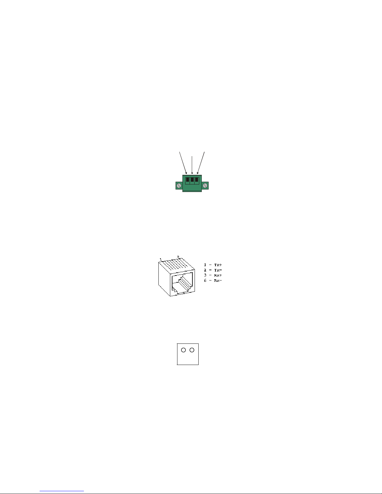
2.1.1 Serial Interface
The TCP2RS has a serial port that supports RS-232 and RS-485 serial standards
(firmware selectable) up to 115.2 Kbps.
Figure 2-1: Serial Interface
2.1.2 Network Interface
The TCP2RS’s contains a reset switch, and an RJ45 (10Base-T) Ethernet port that
supports up to 10 Mbps.
Figure 2-2: Network Interface
2.1.3 LEDs
Six LEDs are located on the top of the unit. The following table explains their functions:
A F
L R
Tx
B(RS-232)
(RS-485) Rx
A(RS-232)
(RS-485)
GND

----------- TCP2RS -------------- User’s manual -------------------- page 8/43
8
Table 2-1: TCP2RS LEDs
LED Function
A (Yellow)
Channel 2 If solid, channel 2 is idle. If blinking (1 sec cycle), the channel is connected
over the network.
F (Red)
Error and
Diagnostic
This LED and LED 2 (Green) together indicate a series of diagnostic patterns.
L (Green)
Network
Link
Active if good link.
R (Green)
Channel 1 It displays the status of channel 1.
If solid, channel 1 is idle. If blinking (1 sec cycle), the channel is connected
over the network. This LED is also used for diagnostic and error detection
when combined with LED 1 (Red)
RX,TX Serial communications.
2.1.4 Product Information Label
A product information label is located on the underside of the TCP2RS, and contains the
following information about your specific unit:
!" Serial Number
!" Product ID (name)
!" Product Description
!" Ethernet Address (also referred to as Hardware Address or MAC Address)
2.2 Installing the TCP2RS
The following diagram shows a properly installed TCP2RS.
To install the TCP2RS, complete the following steps in order. Refer to the numbers in the
previous figure.
1 Connect a serial device to the TCP2RS.
2 Connect an Ethernet cable to the 10BASE-T port.

----------- TCP2RS -------------- User’s manual -------------------- page 9/43
9
3 Supply power to the TCP2RS.
Note: The required input voltage is 220VAC.
4 Supply power to the serial device.
3: Getting Started
This chapter covers the required steps to get the TCP2RS on-line and working. There are
two basic methods used to log into the TCP2RS and setup the IP address:
!" Network Port Login: Make a Telnet connection to the network port (port 9999).
!" Serial Port Login: Connect a terminal or a PC running a terminal emulation
program directly to the TCP2RS’s serial port.
It is important to consider the following points before logging into and configuring the
TCP2RS:
!" The TCP2RS’s IP address must be configured before a network connection is
available.
!" Only one person at a time may be logged into the configuration port (port 9999).
This eliminates the possibility of several people simultaneously attempting to
configure the TCP2RS.
!" Network port logins cannot be disabled. The system manager will always be able
to access the unit. However, this port can be password protected.
!" Only one terminal at a time can be connected to the serial port. (In RS-485 mode,
the TCP2RS is capable of multidrop connections.)
3.1 Default IP Address
The TCP2RS ships with a default IP address of 192.168.0.25, if you want to use DHCP
you have to config IP 0.0.0.0 which automatically enables DHCP within the TCP2RS.
Provided a DHCP server exists on the network, it will supply the TCP2RS with an IP
address, gateway address, and subnet mask when the TCP2RS boots up. (If no DHCP
server exists, the TCP2RS will respond with a diagnostic error: the red Diagnostic LED

----------- TCP2RS -------------- User’s manual -------------------- page 10/43
10
blinks continuously and the green Status LED blinks five times). This address will not
appear in the TCP2RS’s configuration screens; however, if you enter Monitor Mode from
the serial port with network connection enabled (see Monitor Mode), and issue the NC
command, you will see the TCP2RS’s IP configuration.
3.2 IP Address Configuration
The TCP2RS’s IP address must be configured before a network connection is available.
If the IP address was not set automatically via DHCP, set it now using a network or serial
port login and the setup (configuration) menu.
3.2.1 Network Port Login (1)
The easiest way for setting up the IP direction of the TCP2RS converter is using the little
utility called TCP2RSSetup that comes with the converter.
First of all we will write down Ethernet address that comes printed on every device label.
This address is unique and different from other network devices. It’s the hardware
address that every interface has (something like 00-20-4A-61-05-19).
Into the “Extras” disc that comes with the converter, there is an Utility called
TCP2RSSetup. This utility is made for configuring the IP address of the converter. Steps:
1- Start the program
2- Insert the Hardware address that comes with the converter, and desired IP
address.
3- Click Configurar (This will assign temporarily an IP address to the converter
and opens an internet explorer page for configuring it)
4- Click Connect and Server Properties
5- Enter desired IP and netmask ans click Update settings
Note: This utility only links IP address with hardware address, but it is not
stored in device’s memory, until we enters into config mode and update
this settings.
3.2.2 Network Port Login (2)
The ARP method is available under UNIX and Windows-based systems. If the TCP2RS
has no IP address, it will set its address from the first directed TCP/IP packet it receives.
1 On a UNIX host, create an entry in the host’s ARP table using the intended IP

----------- TCP2RS -------------- User’s manual -------------------- page 11/43
11
address and the hardware address of the TCP2RS, which is found on the product
label.
Figure 3-1: ARP on UNIX
arp -s 191.12.3.77 00:20:4a:xx:xx:xx
In order for the ARP command to work on Windows, the ARP table on the PC must
have at least one IP address defined other than its own. If the ARP table is empty, the
command will return an error message. Type ARP -A at the DOS command prompt to
verify that there is at least one entry in the ARP table.
If the local machine is the only entry, ping another IP address on your network to build a
new entry in the ARP table; the IP address must be a host other than the machine on
which you are working. Once there is at least one additional entry in the ARP table, use
the following command to ARP an IP address to the TCP2RS:
Figure 3-2: ARP on Windows
arp -s 191.12.3.77 00-20-4a-xx-xx-xx
2 Now open a Telnet connection to port 1. The connection will fail quickly, but the
TCP2RS will temporarily change its IP address to the one designated in this step.
Figure 3-3:
telnet 191.12.3.77 1
Telnet to Port 1
3 Finally, open a Telnet connection to port 9999 and set all required parameters.
Figure 3-4: Telnet to Port 9999
telnet 191.12.3.77 9999
Note: This IP address is temporary and will revert to the default value
when the TCP2RS’s power is reset, unless you log into the TCP2RS
and store the changes permanently. Refer to Chapter 4 for
instructions on permanently configuring the IP address.
3.2.3 Serial Port Login
1 Connect a console terminal or PC running a terminal emulation program to the
TCP2RS’s serial port. The default serial port settings are 9600 baud, 8 bits, no
parity, 1 stop bit.

----------- TCP2RS -------------- User’s manual -------------------- page 12/43
12
2 To enter Setup (configuration) Mode, cycle the TCP2RS’s power (power off and
back on). After power-up the self-test begins and the red Diagnostic LED starts
blinking. You have one second to enter three lowercase "x" characters.
Note: The easiest way to enter Setup Mode is to hold down the “x” key at
the terminal (or emulation) while powering up the TCP2RS.
3 Select 0(Server Configuration) and follow the prompts until you get to IP address.
4 Enter the new IP address.
5 Select 9to save the configuration and exit Setup Mode.
The TCP2RS performs a power reset.

----------- TCP2RS -------------- User’s manual -------------------- page 13/43
13
4: Configuration
Certain parameters must be configured before the TCP2RS can function on a network.
The TCP2RS can be locally or remotely configured using the following procedures:
!" Use a standard Web browser to access the TCP2RS’s internal Web pages and
configure the unit over the network. This is the easiest and preferred method.
!" Use a Telnet connection to configure the unit over the network.
!" Use a terminal or terminal emulation program to access the serial port locally.
The TCP2RS’s configuration is stored in nonvolatile memory (NVRam) and is retained
without power. The configuration can be changed at any time. The TCP2RS performs a
reset after the configuration has been changed and stored.
4.1 Network Configuration
4.1.1 Using a Web Browser
If your TCP2RS already has an IP address (see Chapter 3, Getting Started), you can log
into it using a standard Web browser with Java enabled.
1 Type the TCP2RS’s IP address into the Web browser’s URL (Address/Location)
field.
Once you have connected to the TCP2RS, you will see the device Web Manager
interface.
2 Select Connect to login and gain access to the configuration menu.
3 Use the menu to navigate to subpages where you can configure server settings.
Figure 4-1: Web Manager Interface

----------- TCP2RS -------------- User’s manual -------------------- page 14/43
14
4.1.2 Using a Telnet Connection
To configure the TCP2RS over the network, establish a Telnet connection to port 9999.
For Windows, open an MS-DOS command window and enter the following command,
where x.x.x.x is the IP address and 9999 is the TCP2RS’s fixed network console port
number.
Figure 4-2:
Telnet x.x.x.x 9999
Network Login Using Telnet
Note: Be sure to include a space between the IP address and 9999.
4.2 Serial Configuration
For local configuration, a terminal or a PC running a terminal emulation program can be
connected to the TCP2RS’s serial port. The terminal (or emulation) should be configured
for 9600 baud, 8-bit, no parity, 1 stop bit and without flow control.
To enter Setup (configuration) Mode, cycle the TCP2RS’s power (power off and back
on). After power-up, the self-test begins and the Diagnostic and Status LEDs start
blinking. You must enter three lowercase "x" characters (xxx) within one second after
powering up in order to start the configuration mode.
Note: The easiest way to enter Setup Mode is to hold down the "x" key on
your keyboard while powering up the TCP2RS.
4.3 Configuration Parameters
After entering Setup Mode (confirm by typing Enter), you can configure the parameters
by entering one of the numbers on the Change Setup Menu, or you can confirm default

----------- TCP2RS -------------- User’s manual -------------------- page 15/43
15
values by typing Enter. Be sure to store the new configurations when you are finished.
The TCP2RS will then perform a power reset.
Figure 4-3: Setup (Configuration) Mode Screen
*** Circutor ***
Serial Number 1400280 MAC address 00:20:4A:14:01:18
Software Version 04.5 (000428)
Press Enter to go into Setup Mode
*** basic parameters
Hardware: Ethernet Autodetect
IP addr 192.168.011.141, no gateway set
***************** Channel 1 *****************
Baudrate 09600, I/F Mode 4C, Flow 00
Port 10001
Remote IP Adr: --- none ---, Port 00000
Connect Mode: C0 Disconn Mode: 00
Flush Mode: 00
Change Setup:0 Server configuration
1 Channel 1 configuration
7 Factory defaults
8 Exit without save
9 Save and exit Your choice ?
Setup Options:
0 Server Configuration IP Address: (192).(168).(000).(030)
Set Gateway IP Address (N) N
Netmask: Number of Bits for Host Part (0=default) (08)
Change telnet config password (N) N
1 Channel 1 Configuration Baudrate (9600)
I/F Mode (4C) ?
Flow (00) ?
Port No (10001) ?
ConnectMode (C0) ?
Remote IP Address : (000).(000).(000).(000)
Remote Port (00000) ?
DisConnMode (00) ?
FlushMode (00) ?
DisConnTime (00 :00) ?
SendChar 1 (00) ?
SendChar 2 (00) ?

----------- TCP2RS -------------- User’s manual -------------------- page 16/43
16
7 Factory defaults Disable Telnet Setup (N) N
Disable TFTP firmware update (N) N
Disable Port 77Feh (N) N
Disable web setup (N) N
Enable enhanced password (N) N
8 Exit without save
9 Save and exit
4.4 Server Configuration
Select 0to configure the TCP2RS’s basic parameters.
4.4.1 IP Address
The IP address must be set to a unique value in your network. See Appendix F for more
information about IP Addressing.
Note: The TCP2RS cannot connect to the network if the assigned IP
address is already in use by another device.
4.4.2 Gateway Address
The gateway address, or router, allows communication to other LAN segments. The
gateway address should be the IP address of the router connected to the same LAN
segment as the TCP2RS.
Note: The gateway address must be within the local network.
4.4.3 Netmask
A netmask defines the number of bits taken from the IP address that are assigned for the
host section.
Note: Class A: 24 bits; Class B: 16 bits; Class C: 8 bits.
The TCP2RS prompts for the number of host bits to be entered, then calculates the
netmask, which is displayed in standard decimal-dot notation when the saved parameters
are displayed (for example, 255.255.255.0).

----------- TCP2RS -------------- User’s manual -------------------- page 17/43
17
4.4.4 Telnet Configuration Password
Setting the Telnet configuration password prevents unauthorized access of the setup
menu via a Telnet connection to port 9999. The password is limited to 4 characters.
Note: No password is required to access the setup menu via a serial
connection.
4.5 Serial Channel (Port) Configuration
Select 1to configure the TCP2RS’s channel-specific parameters.
4.5.1 Baud Rate
The TCP2RS and attached serial device, such as a modem, must agree on a speed or baud
rate to use for the serial connection. Valid baud rates are 300, 600, 1200, 2400, 4800,
9600 (default), 19200, 38400, 57600, and 115200 bits per second.
4.5.2 Interface Mode
The Interface (I/F) Mode is a bit-coded byte entered in hexadecimal notation.
Table 4-1: Interface Mode Options
Option Bit 7 6543210
RS-232C 0 0
RS-485 0 1
RS-485 2-wire 1 1
7 Bit 1 0
8 Bit 1 1
No Parity 0 0
Even Parity 1 1
Odd Parity 0 1
1 Stop bit 0 1
2 Stop bits 1 1
The following table demonstrates how to build some common Interface Mode settings:
Table 4-2: Common Interface Mode Settings
Option Binary Hex
RS-232C, 8-bit, No Parity, 1 stop bit 0100 1100 4C

----------- TCP2RS -------------- User’s manual -------------------- page 18/43
18
RS-232C, 7-bit, Even Parity, 1 stop bit 0111 1000 78
RS-485 2-Wire, 8-bit, No Parity, 1 stop bit 0100 1111 4F
Note: See Appendix B for more information on converting binary values to
hexadecimal format.
4.5.3 Flow Control
Flow control sets the local handshake method for stopping serial input/output. Generally,
flow control is not required if the connection is used to pass a blocked protocol with
block sizes less than 1k (ACK/NAK).
Table 4-3: Flow Control Options
Option Hex
No flow control 00
XON/XOFF flow control 01
Hardware handshake with RTS/CTS lines 02
XON/XOFF pass characters to host 05
4.5.4 Port Number
The setting represents the source port number in TCP connections, and is the number
used to identify the channel for remote initiating connections. Range: 1-65535.
Note: Port numbers 0, 7, and 9999 are reserved. Port numbers 14000-
14009 are reserved for use with the Comm Port Redirector
application (see Comm Port Redirector on page 5-1).
If the UDP mode is selected, the port number functions as the UDP source port number
for outgoing datagrams. Datagrams sent to the TCP2RS with this port number are
received to this channel.
4.5.5 Connect Mode
Connect Mode defines how the TCP2RS makes a connection, and how it reacts to
incoming connections over the network.
Table 4-4: Connect Mode Options
Option Bit 7 6543210

----------- TCP2RS -------------- User’s manual -------------------- page 19/43
19
Incoming Connection
Never accept incoming 0 0 0
Accept incoming with DTR 0 1 0
Accept unconditional 1 1 0
Response
Nothing(quiet) 0
Character response (C=conn,
D=disconn, N=unreachable) 1
Startup
No active startup 0 0 0 0
With any character 0 0 0 1
With active DTR 0 0 1 0
With CR (0x0D) only 0 0 1 1
Manual connection 0 1 0 0
Autostart 0 1 0 1
Datagram Type
Directed UDP 1 1 0 0
Modem Mode
With Echo 1 0 1 1 0
Without Echo 0 0 1 1 0
Note: See Appendix B for information on converting binary values to
hexadecimal format.
4.5.5.1 Manual Connection
If manual connection startup is configured (C+ address/port), only the portion not
provided in the command string is used. In manual mode, the last byte of the address
must be provided.
For example, if the TCP2RS’s configured remote IP address is 129.1.2.3 and the TCP
port number is 1234:
Table 4-5: Manual Connection Address Example
Command String Result
C121.2.4.5/1 Complete override; connection is started with host
121.2.4.5, port 1
C5 Connect to 129.1.2.5, port 1234
C28.10/12 Connect to 129.1.28.10, port 12
4.5.5.2 Autostart (Automatic Connection)

----------- TCP2RS -------------- User’s manual -------------------- page 20/43
20
For the serial port, automatic TCP connection to a network node can be configured by
setting the remote IP address and the TCP port number parameters. If automatic
connection is selected, all parameters must be provided.
4.5.5.3 Datagram Type
When selecting this option, you will be prompted for the Datagram type. Enter 01 for
directed UDP.
4.5.5.4 Modem (Emulation) Mode
In Modem Mode, the TCP2RS presents a modem interface to the attached serial device.
It accepts AT-style modem commands, and handles the modem signals correctly.
Normally there is a modem connected to a local PC and a modem connected to a remote
machine. A user must dial from the local PC to the remote machine, accumulating phone
charges for each connection. Modem Mode allows you to replace modems with TCP2RS,
and to use an Ethernet connection instead of a phone call, without having to change
communications applications and make potentially expensive phone calls.
Note: If the TCP2RS is in Modem Mode and the serial port is idle, the
TCP2RS can still accept network TCP connections to the serial port
if Connect Mode is set to C6 (no echo) or D6 (echo).
Modem Mode is selected by setting the connect mode to 06 (no echo) or 16 (echo).
Table 4-6: Modem Mode Commands
Command Function
ATDTx.x.x.x,pppp or
ATDTx.x.x.x/pppp Makes a connection to an IP address (x.x.x.x) and a remote port
number (pppp).
ATDTx.x.x.x Makes a connection to an IP address (x.x.x.x) and the remote port
number defined within the TCP2RS.
ATD0.0.0.0 Forces the TCP2RS into monitor mode if a remote IP address and
port number are defined within the TCP2RS.
ATD Forces the TCP2RS into monitor mode if a remote IP address and
port number are not defined within the TCP2RS.
ATDx.x.x.x Makes a connection to an IP address (x.x.x.x) and the remote port
number defined within the TCP2RS.
ATH Hangs up the connection (Entered as +++ATH).
Note: All other AT commands with Modem Mode set to 16 acknowledge
with an OK, but no action is taken.
Table of contents
Other Circutor Media Converter manuals


Popular Media Converter manuals by other brands

Wintal
Wintal SX-HVY01 operating instructions

Link
Link HD & SDI Frame Synchronizer HFS-975 Specification sheet

ROLENCE ENTERPRISE
ROLENCE ENTERPRISE ELiTEDENT MS-10B user manual

Relectronic
Relectronic C-58 Series user manual

Transition Networks
Transition Networks SBFTF10XX-15X user guide

DENTSPLY
DENTSPLY Cavitron G139 Directions for use


