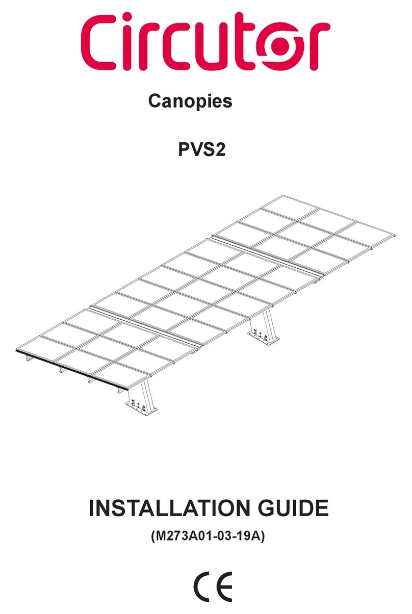
Circutor PVS2 User manual

INSTALLATION GUIDE
(M273A01-03-21A)
Canopies
PVS2, PVS2-R

2
PVS2, PVS2-R
Installation Guide

SAFETY PRECAUTIONS
DISCLAIMER
CIRCUTOR, SA reserves the right to make modifications to the device or the unit specifications set
out in this instruction manual without prior notice.
CIRCUTOR, SA on its web site, supplies its customers with the latest versions of the device specifica-
tions and the most updated manuals.
www.circutor.com
CIRCUTOR, recommends using the original cables and accessories that are supplied
with the device.
DANGER
Warns of a risk, which could result in personal injury or material damage.
ATTENTION
Indicates that special attention should be paid to a specific point.
Follow the warnings described in this manual with the symbols shown below.
If you must handle the unit for its installation, start-up or maintenance, the following should be
taken into consideration:
Incorrect handling or installation of the unit may result in injury to personnel as well as damage to the
unit. In particular, handling with voltages applied may result in electric shock, which may cause death
or serious injury to personnel. Defective installation or maintenance may also lead to the risk of fire.
Read the manual carefully prior to connecting the unit. Follow all installation and maintenance in-
structions throughout the unit’s working life. Pay special attention to the installation standards of the
National Electrical Code.
Refer to the instruction manual before using the unit
In this manual, if the instructions marked with this symbol are not respected or carried out correctly, it can result
in injury or damage to the unit and/or installations.
CIRCUTOR, SA reserves the right to modify features or the product manual without prior notification.
3
Installation Guide
PVS2, PVS2-R

CONTENTS
SAFETY PRECAUTIONS .........................................................................................................................................................3
DISCLAIMER ..........................................................................................................................................................................3
CONTENTS.............................................................................................................................................................................4
REVISION LOG .......................................................................................................................................................................6
1. WARRANTY CERTIFICATE FOR THE CANOPIES ...............................................................................................................7
2. FORESEEABLE MISUSE ...................................................................................................................................................8
3. PVS2 MODELS .................................................................................................................................................................9
3.1.- CONFIGURATIONS .................................................................................................................................................. 10
4. COMPONENTS ............................................................................................................................................................... 12
4.1.- FEET AND WINGS................................................................................................................................................ 13
4.2.- BEAMS, PROFILES AND FASTENING OF MODULES............................................................................................ 14
5. PREPARATION OF THE INSTALLATION......................................................................................................................... 15
5.1.- STUDY INTO THE ELECTRICAL PROJECT................................................................................................................ 15
5.1.1.- STANDARD INSTALLATION WITH RECHARGE POINT IN START FOOT............................................................ 15
5.1.2.-STANDARD INSTALLATION WITH RECHARGE POINT IN START AND END FOOT ............................................ 15
5.1.3.- MAJOR INSTALLATION................................................................................................................................... 16
5.1.4.- INTERNAL CONNECTION OF FEET................................................................................................................. 16
5.2.- PREPARATION OF FOOTINGS................................................................................................................................. 17
5.3.- EARTH CONNECTION............................................................................................................................................. 18
5.4.- ASSEMBLE TEMPLATES......................................................................................................................................... 18
5.5.- FILLING THE FOOTINGS......................................................................................................................................... 19
6. ASSEMBLY OF FEET AND WINGS .................................................................................................................................20
6.1.- BASE INSTALLATION.............................................................................................................................................20
6.2.- BASE ALIGNMENT ................................................................................................................................................20
6.3.- FEET AND WINGS UNION ...................................................................................................................................... 21
6.4- UNION WITH THE BASE ..........................................................................................................................................22
6.5- ALIGNMENT OF THE FEET......................................................................................................................................23
7. ASSEMBLY OF BEAMS ...................................................................................................................................................24
7.1- FITTING OF ANGLES ................................................................................................................................................24
7.2- BEAM ANGLES ........................................................................................................................................................25
7.3 - FITTING OF BEAMS ...............................................................................................................................................26
7.4 - INSTALLATION OF GROUND POINT .......................................................................................................................27
8. PROFILES AND MODULES.............................................................................................................................................28
8.1 - INTERMEDIATE PROFILES .....................................................................................................................................28
8.2 - FINAL PROFILES ....................................................................................................................................................28
8.3 - PREPARATION OF PROFILES ................................................................................................................................29
8.4 - FITTING OF INTERMEDIATE PROFILES (1) .............................................................................................................30
8.5 - FITTING OF INTERMEDIATE PROFILES (2)............................................................................................................. 31
8.6 - FITTING OF FINAL PROFILES (1)............................................................................................................................32
8.7 - FITTING OF FINAL PROFILES (2)............................................................................................................................33
8.8 - SETTING MODULES A ............................................................................................................................................34
8.9 - SETTING MODULES B ............................................................................................................................................35
8.10 - CONNECTION OF STRINGS ...................................................................................................................................36
8.11 - PROBE PLACEMENT..............................................................................................................................................37
9. FINAL FOUNDATIONS....................................................................................................................................................38
10. INSTALLATION OF THE CHARGER ...............................................................................................................................39
10.1 - INSTALLATION OF THE PVS2 CHARGER................................................................................................................39
10.2 - INSTALLATION OF THE PVS2-R CHARGER ...........................................................................................................40
10.2.1.- PLACE THE FRAME........................................................................................................................................40
10.2.2.- POSITION THE FRONT COVERS OF THE CHARGERS..................................................................................... 41
10.2.3.- SINGLE PHASE INSTALLATION WITH 2 SOCKETS ........................................................................................42
10.2.4.- THREE PHASE INSTALLATION WITH 2 SOCKETS..........................................................................................43
11. USAGE AND MAINTENANCE.........................................................................................................................................44
11.1 - INSTALLATION .......................................................................................................................................................44
11.1.1.- ASSEMBLY ACCORDING TO MANUFACTURER SPECIFICATIONS ....................................................................44
11.1.2.- DIFFICULTIES AND VARIATIONS DURING ASSEMBLY ....................................................................................44
11.1.3.- BONDING OF PARTS AND TIGHTENING TORQUE...........................................................................................44
11.1.4.- FOUNDATIONS, ALIGNMENT AND LEVELLING OF THE CANOPIES................................................................44
11.1.5.- LOCATION AND CHARACTERISTICS OF THE INSTALLATION ZONE ...............................................................44
4
PVS2, PVS2-R
Installation Guide

11.2 - USE AND UPKEEP .................................................................................................................................................45
11.2.1.- STRUCTURAL ELEMENTS MUST NOT BE MODIFIED.....................................................................................45
11.2.2.- USAGE OVERLOAD INDICATED IN THE PROJECT MUST NOT BE EXCEEDED................................................45
11.2.3.- THE ORIGINAL STATUS OF THE ELEMENTS OF THE CANOPY CANNOT BE MODIFIED .................................45
11.2.4.- AVOID THE CONTACT OF THE STEEL WITH OXIDISING OR AGGRESSIVE ELEMENTS...................................45
11.3 - REVISION AND MAINTENANCE .............................................................................................................................45
11.3.1.- GENERAL CONDITIONS ..................................................................................................................................45
11.3.2.- REVISION AND MAINTENANCE TASKS ..........................................................................................................46
11.3.3.- CASES THAT INVOLVE SPECIAL REVIEWS.....................................................................................................47
12. MAINTENANCE AND TECHNICAL SERVICE..................................................................................................................48
13. CE CERTIFICATE ...........................................................................................................................................................49
5
Installation Guide
PVS2, PVS2-R

REVISION LOG
Table 1: Revision log.
Date Revision Description
08/19 M273A01-03-19A Initial version
09/21 M273A01-03-21A
Changes in the following sections:
3.- 4. - 4.1.- 4.2.- 5.1.4.- 5.2.- 5.4.- 5.5.- 6.- 7.4.- 8.-
10.- 13.
Note: The images of the devices are for illustrative purposes only and may differ from the original
device.
6
PVS2, PVS2-R
Installation Guide

1. WARRANTY CERTIFICATE FOR THE CANOPIES
10 year Warranty for defects in materials or manufacturing flaws
CIRCUTOR hereby guarantees, for a period of 10 years, from the date of delivery to the buyer, that its
canopies are free of any defect in their materials or manufacture that hinder their normal operation
under proper conditions of usage, installation and maintenance.
If, at any time, during the period of validity of this guarantee, the appearance of defects in their materials
or their manufacture occurs, CIRCUTOR undertakes to replace the defective structure.
The guarantees contained in this Certificate will be provided by CIRCUTOR subject to the general terms
and conditions expressed below:
Exclusions and Limitations of Guarantees
Those damages and faults established herein will be exempt from the warranty rights whenever
these arise from:
1.- Accidents or negligent, improper or unsuitable use.
2.- Failing to respect the installation, usage and maintenance instructions set forth.
CIRCUTOR reserves the right to supply a different model of structure to handle the accepted warranty
claims, for replacement or expansion, in the event that the original model was no longer manufactured.
Admitted usage
This type of canopy is a metallic structure with two basic functions:
To support a cover of photovoltaic solar modules or thermal solar panels, for the production of
running or hot water respectively.
To protect motor vehicles, motorcycles, bicycles, people, etc. from the sun and the rain under the
cover.
7
Installation Guide
PVS2, PVS2-R

2. FORESEEABLE MISUSE
This type of canopy is not intended to:
To withstand overloads higher than those indicated in the corresponding certificate of technical
characteristics, due to meteorological conditions (snow and wind) of the site and the own weight of
the solar panels.
People will not be allowed to climb onto the canopy, with the exception of those who access it to
carry out maintenance and assembly tasks. No more than one person with their personal work material
(100 kg) may climb onto the canopy.
It is not allowed to cover the sides, front or rear with any type of enclosure that wholly or partially
prevents the passage of the wind.
The installation of posters or jutting elements is not allowed, nor in general, any added element that
increases the surface exposed to the wind.
Only the assembly of original parts and components supplied by CIRCUTOR is allowed.
CIRCUTOR will not be held liable for any unauthorised modification to the canopy, once the same
has been put into service.
If a wall is installed along the entire length of the canopy, a special study will be required to vary the
coefficient of obstruction contemplated in the calculation.
Figure 1: Variation of the obstruction coefficient.
If the canopy is installed in the vicinity of a height change or on a steep wall or mound that increases
the height of the canopy above the ground level to more than 3 m in height at the centre point of
the roofing, a special study will be required owing to the modification of the pressure and suction
coefficients considered in the calculation.
8
PVS2, PVS2-R
Installation Guide

3. PVS2 MODELS
PVS2
3 5 17
2578
12°
PVS2-R
490
3550,83
920
12°
2506,62
Figure 2: Models.
Model Length kWp Modules Feet
PVS- 2 5,0 m 5 kWp 15 1
PVS- 3 8,0 m 8 kWp 24 2
PVS- 4 10,0 m 10 kWp 30 2
PVS- 5 13,0 m 13 kWp 39 2
PVS- 6 15,0 m 15 kWp 45 3
PVS- 8 20,0 m 20,10 kWp 60 3
PVS- 10 25,0 m 25,13 kWp 75 4
9
Installation Guide
PVS2, PVS2-R

3.1.- CONFIGURATIONS
PVS2-2-R
3550,83
12°
2506,62
PVS2-3
3 5 17
2578
12°
PVS2-3-R
3550,83
12°
2506,62
PVS2-4
3 5 17
2578
12°
PVS2-4-R
3550,83
920
12°
2506,62
PVS2-5
3 5 17
2 5 7 8
12 °
10
PVS2, PVS2-R
Installation Guide

PVS2-5-R
3550,83
920
12°
2506,62
PVS2-6
3 5 17
2578
12°
PVS2-6-R
3550,83
920
12°
2506,62
PVS2-8
3 5 17
2578
12°
PVS2-8-R
3550,83
920
12°
2506,62
PVS2-10
3517
2 5 7 8
12°
PVS2-10-R
2 5 7 8
3550,83
920
12°
11
Installation Guide
PVS2, PVS2-R

4. COMPONENTS
PROFILE
BASE
FOOT
WING
BEAM
PV MODULES
Figure 3: PVS2, PVS2-R components.
12
PVS2, PVS2-R
Installation Guide

4.1.- FEET AND WINGS
RIGHT VIEW
LEFT VIEW
WING START
PV ANGLE BEAM C
V WING ANGLE
PVS CNJTO. PATA CON REG.
Table 2: Bolts.
Bolts
DIN 931 M20x280 18 u.
DIN 603 M10x25 8 u.
M10x50 8 u.
DIN 6923 M10 16 u.
DIN 934 M24 Zn 24 u.
M24 4 u.
M20 18 u.
DIN 9021 M24 8 u.
M20 36 u.
13
Installation Guide
PVS2, PVS2-R

4.2.- BEAMS, PROFILES AND FASTENING OF MODULES
PVS2- 2 15 4 4 2 0 24 10 60
PVS2- 324 4 7 0 12 36 16 96
PVS2- 4 30 4 9 2 0 52 20 120
PVS2- 5 39 4 12 2 0 56 26 156
PVS2- 6 45 8 14 2 0 76 30 180
PVS2- 8 60 8 18 2 0 84 40 240
PVS2- 10 75 12 23 1 6 104 50 300
M10
Model MODULES BEAMS PROFILE PROFILE LAT. TORN. Cross-sectional Profile CLAMP
Figure 4: Beams, profiles and fastening of modules.
14
PVS2, PVS2-R
Installation Guide

5. PREPARATION OF THE INSTALLATION
5.1.- STUDY INTO THE ELECTRICAL PROJECT
5.1.1.- STANDARD INSTALLATION WITH RECHARGE POINT IN START FOOT
Lowering of strings (DC wiring) per start foot.
Power supply to recharging point in start foot (AC wiring).
Figure 5: Standard installation with recharging point in start foot.
5.1.2.-STANDARD INSTALLATION WITH RECHARGE POINT IN START AND END FOOT
Lowering of strings (DC wiring) per start foot.
Power supply to recharging point in start and end foot (AC wiring).
Figure 6: Standard installation with recharging point in start and end foot.
15
Installation Guide
PVS2, PVS2-R

5.1.3.- MAJOR INSTALLATION
Lowering of strings (DC wiring) per start and central foot.
Power supply of recharging points in each foot. (AC wiring)
Figure 7: Major installation.
5.1.4.- INTERNAL CONNECTION OF FEET
WING-STRAP
FOOT-WING
GROUND-FOOT
(SEE DETAILS IN
POINT 7.4)
Figure 8: Internal connection of feet.
16
PVS2, PVS2-R
Installation Guide

5.2.- PREPARATION OF FOOTINGS
MAX
10º
300mm
MAX
D
D
CASKET
REINFORCED TWIN-LAYER PIPE
MAXIMUM CAPACITY PER FOOT OF 4 TUBES, 40mm DIAMETER
PROJECTION OF A LENGTH OF 6 M APPROXIMATELY FROM CASKET SPLICE FOR THE LOWERING OF STRINGS,
DC WIRING.
IF IT IS ONLY FOR AC WIRING OF THE CHARGER, PROJECTION OF 4 M APPROXIMATELY OF CASKET SPLICE.
LEAVE CABLES IN
PLACE
CASKET FOOTING
FOOTING ALIGNMENT
SPLICE BOX
Figure 9: Preparation of footings.
17
Installation Guide
PVS2, PVS2-R

5.3.- EARTH CONNECTION
ON EACH FOOT
CASKET
FOOT TUBE
Figure 10: Earth connection.
5.4.- ASSEMBLE TEMPLATES
36x
M24
Torque (kp·m): 71
50
50
500
950
Figure 11: Assembly of templates.
18
PVS2, PVS2-R
Installation Guide

5.5.- FILLING THE FOOTINGS
QUITAR PLANTILLA SUPERIOR
5.6
Figure 12: Filling the footings.
19
Installation Guide
PVS2, PVS2-R

6. ASSEMBLY OF FEET AND WINGS
6.1.- BASE INSTALLATION
6x
M24
6x
D24
Torque (kp·m): 71
PULL THE TUBES WHEN
LIFTING
DO NOT STEP ON THE
TUBES
Figure 13: Base installation.
6.2.- BASE ALIGNMENT
XY
X=Y
A//B
AB
Figure 14: Base alignment.
20
PVS2, PVS2-R
Installation Guide
Other manuals for PVS2
1
This manual suits for next models
21
Table of contents
Other Circutor Tent manuals
