Cirs 769 User manual
USER GUIDE
Doppler Flow Pump
Model 769
900 Asbury Ave • Norfolk, Virginia 23513 • USA • Tel: 757-855-2765 • WWW.CIRSINC.COM


Overview . . . . . . . . . . . . . . . . . . . . . . . . . . . .2
Specications . . . . . . . . . . . . . . . . . . . . . . . . . . 5
Instructions for Use . . . . . . . . . . . . . . . . . . . . . . . 7
Program Pulsitile Flow . . . . . . . . . . . . . . . . . . . . . . 9
Contrast Injection Setup . . . . . . . . . . . . . . . . . . . . 10
Calibration and Resetting . . . . . . . . . . . . . . . . . . . . 10
Care and Handling . . . . . . . . . . . . . . . . . . . . . . . 11
Appendix 1: Pump Calibration . . . . . . . . . . . . . . . . . . 12
Warranty . . . . . . . . . . . . . . . . . . . . . . . . . . . 13
Table of Contents
The Doppler Flow Pump is used to simulate blood ow when testing Doppler ultrasound devices. When used
in conjunction with a tissue mimicking phantom (sold separately; a list of compatible CIRS phantoms is on the
back), the ow pump supports routine Doppler quality assurance measurements of velocity accuracy, direc-
tional accuracy, sample volume accuracy and sensitivity. The congurable design also supports advanced
research and engineering tests. For instance, test circuit may be modied to support either constant veloc-
ity ow or pulsatile ow. When in pulsatile ow mode, the peristaltic pump may be programmed to produce
physiologic waveforms. In addition, the external tubing circuit ensures laminar ow rates over a wide range of
ow rates, and it allows users to easily inject contrast agents for testing contrast enhanced ultrasound (CEUS).
The pump comes in a plastic ABS housing that conveniently stores all accessories needed for setting up a
ow circuit, as described in the next section.
Overview

Included with Model 769
The CIRS Doppler Flow Pump consists of the following parts:
1. Peristaltic Pump. The pump provides ow rates of 0.5 to 12.5 ml/s, which translates to an average ow
velocity of 2-70 cm/s in a vessel with a 3/16” inside diameter. (Peak ow velocities will be 2-4 times greater
than the average ow velocity because of laminar and pulsatile ow). For more information on ow rates and
ow velocities, consult the Tables in Appendix 1.
2. CIRS Doppler uid and User Guide. The uid comes in a ½ gallon container that doubles as a uid reservoir.
More uid may be purchased separately at www.CIRSinc.com (CIRS model 769DF). See Doppler uid User
Guide for more information
3. Graduated Cylinder. Located next to the Doppler uid reservoir, the 500 ml graduated cylinder is used in
pump calibration and provides a handy transfer reservoir when purging phantoms of Doppler uid after each
use.
4. Pulse dampener. The pulse dampener evens out the pressure pulse from the peristaltic pump to deliver
constant velocity ow within the test circuit. Constant velocity ow is required for many quality assurance
test procedures for doppler ultrasound systems. Please note pulse dampener will always have a small
amount of Doppler uid remaining after each use. This is normal. The pulse dampener will not leak in stor-
age. Be sure to not get water in the dampener, as this will dilute the doppler uid, ruining its ability to mimic
blood under ultrasound.
5. Tubing Pack. The color-coded tubing comes with quick-disconnect ttings for easy setup.
6. Control Cables. Computer control of the peristaltic pump is possible through a pump-to-USB cable. See
Program Pulsatile Flow for instructions on downloading the control software and programing the pump.
3
QTY COMPONENT DESCRIPTION
1Blue 3/16” cassette with white rotor
2pump head tubing with quick disconnect ttings (two male each)
1container of pump head lubricant
QTY COMPONENT DESCRIPTION QUICK DISCONNECT FITTINGS
2red 3/8” outer diameter tubing one male, one female
1blue 3/8” outer diameter tubing two male
1reservoir cap with two uid ports two female
2ATS phantom adapters one male (each)

5
Specications
GENERAL SAFETY NOTICE
The pump provided is pre-set to operate with 3/16” inner diameter tubing. To achieve ow rates lower than the minimum rates those listed
below, the pump may be accommodated with 1/16” inner diameter tubing. Please contact CIRS to obtain a conversion kit to enable lower ow
rates with this pump.
PUMP SAFETY INFORMATION
Motor type: Step motor
Motor steps per revolution: 200
Microstepping: 1/8 to 1/1 depending on motor speed
DC connector: 2.1mm, center positive
Voltage at DC connector: 24V DC at full load
Amperage: 900mA at full load
Power supply type: Unregulated linear external wall adapter, country and
power source specic
Power supply output rating: 24V DC @ 1A
Dimensions: 7 ¾” x 5 1/4” x 5 3/4” High
(19.685 cm x 13.335 cm x 14.605 cm)
Weight: 4.51 lbs. (2.05 kg)
Maximum speed: 372 rpm
Minimum speed: 0.0168 rpm
Maximum pumping rate: 775.2 mL/min with 3/16 ID tubing
Minimum pumping rate: 0.035 mL/min with 3/16 ID tubing
This product is designed for use with CIRS Doppler Fluid and water (for cleaning purposes) only. Use of other uids (or non-liquids) may result in
damage to the pump.
Turn the pump off when re-conguring the system setup. Failure to do so may result in accidental spillage.
Review the enclosed Doppler uid User’s Guide for more information on the safe handling and disposal of Doppler uid.
WARNING: THE LIST BELOW PROVIDES INFORMATION THAT,
IF IGNORED OR APPLIED INCORRECTLY, CREATES THE POSSI-
BILITY OF DEATH OR SERIOUS INJURY. IE. FIRE, EXPLOSION.
!
• Read the user’s manual.
• This product is designed for liquid only.
• User is responsible to determine the suitability of the pump to its desired function.
• Verify that tubing is appropriate for liquid being pumped.
• Disconnect power from the pump when replacing tubing or connecting or disconnecting cables.

6
• Never leave any dangerous liquid inside of tubing when replacing tubing and disposing pump. Use of liquids other than CIRS Doppler
Fluid or water is not recommended.
• Never use in atmosphere with ammable gas.
• Never use in any location where there is a possibility of high humidity, high temperature, or extreme dust.
• Use only with the supplied power supply connected to a power source as specied on the power supply label.
• Never use a voltage that is different from voltage specied in this manual, unless authorized by CIRS.
• Do not operate with any foreign matter (water, dirt, metal or other materials) inside the Pump-head.
• Do not push objects of any kind into the chassis openings, except for appropriate cables and connectors.
• Never try to take the unit apart or modify it except as described in this manual or authorized by CIRS. No user serviceable parts inside.
• Do not immerse the pump in liquid. If spilling occurs unplug pump immediately.
• Install on a stable surface.
• The pump can automatically start when the Pumping Program is operating or when attached to an external control device.
• Prevent liquids from entering openings in the rear of the pump.
• If the pump becomes damaged, do not use unless certied safe by a qualied technician. Damage includes, but is not excluded
to ,frayed cords and deterioration in performance.
• Do not transport and store this product where the temperature and the humidity are high or uctuate greatly, or the product is subjected
to direct sunlight.
• Remove tubing from pump when not in use. Tubing will become deformed changing dispensed volume per rotation.
• Tubing wall may become permanently damaged if the roller compresses the same part of the tubing for a long time.
• During installation and use, be careful not to cut yourself on the edge of the Pump parts.
• Tubing life depends upon chemical and operating environment.
• Tubing Chemical compatibility list mentioned is only a guide. The user is responsible to determine the tubing compatibility to the chemi-
cal to be used.
• Keep delivery and suction lines as short as possible, use a minimum number of bends.
• Pump operates best at medium speeds. At very slow speeds pump will get hot. At high speeds pump and tubing life will decrease,
pump will lose force/ pressure and may stall.
• Run at slow speed and use larger diameter tubing when pumping viscous liquid.
• User is responsible to determine the maximum speed the pump can operate.
• Discharge static from control cables before connecting by touching the cable to ground.
• Before touching the pump, discharge static by touching ground.
CAUTION: THE LIST BELOW PROVIDES INFORMATION THAT, IF
IGNORED OR APPLIED INCORRECTLY, CREATES THE POS-
SIBILITY OF MINOR OR MODERATE PERSONAL INJURY OR
PROPERTY DAMAGE
!
7
Instructions for Use
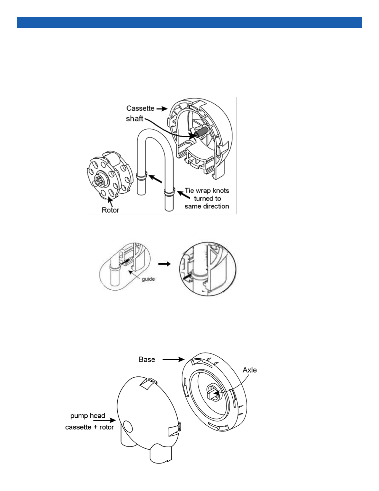
1. Assemble the pump head assembly
− Remove rotor from cassette (see gure below). Add grease to pump Shaft and pump Tubing.
(Tubing comes pre-cut with Quick-Disconnect ttings and tie-wraps spaced 5 3/8” apart.)
− Place tubing into the guide of the cassette, tie wrap knots facing cassette. This will be a tight t
and will NOT snap into place.
− Tuck the edge of the rotor under the center of tubbing, so the tubbing is resting between the yel
low wheels of the rotor.
− Push the rotor onto the shaft. Note that the rotor has two sides: one with a circle and one with a
cross. Only the circle side will t onto the shaft.
− Install the pump head onto base by rst lining up rotor and driving axle, then applying forward
pressure and rotating cassette clockwise until it enters its groove. Continue turning until it stops.

8
2. Prepare pump for operation
− Plug in the pump. Use appropriate power supply. (220V power supply is available. Please contact CIRS.)
− Press the power switch on the back of the pump to turn on power.
− Press any key to stop the display from blinking.
3. Setup Pump for Continuous Flow:
− Display the pumping rate by momentarily pressing the ‘Rate’ key.
− Momentarily press the ‘Rate’ key again. The display will show:
− Press any up arrow key to select the rate units until the “mL” and “min” indicators are lit.
− Press ‘rate’ key, or wait for the time out to set the rate units.
− Set the pumping rate using the arrow keys. If the pumping rate is out of range, the display will show:
− Display the volume by momentarily pressing the ‘Volume’ key. ‘Dispensed’ LED should be off. Press the up arrow
keys to change the display to 0; once entered the display will show which means the pump is set for con-
tinuous pumping.
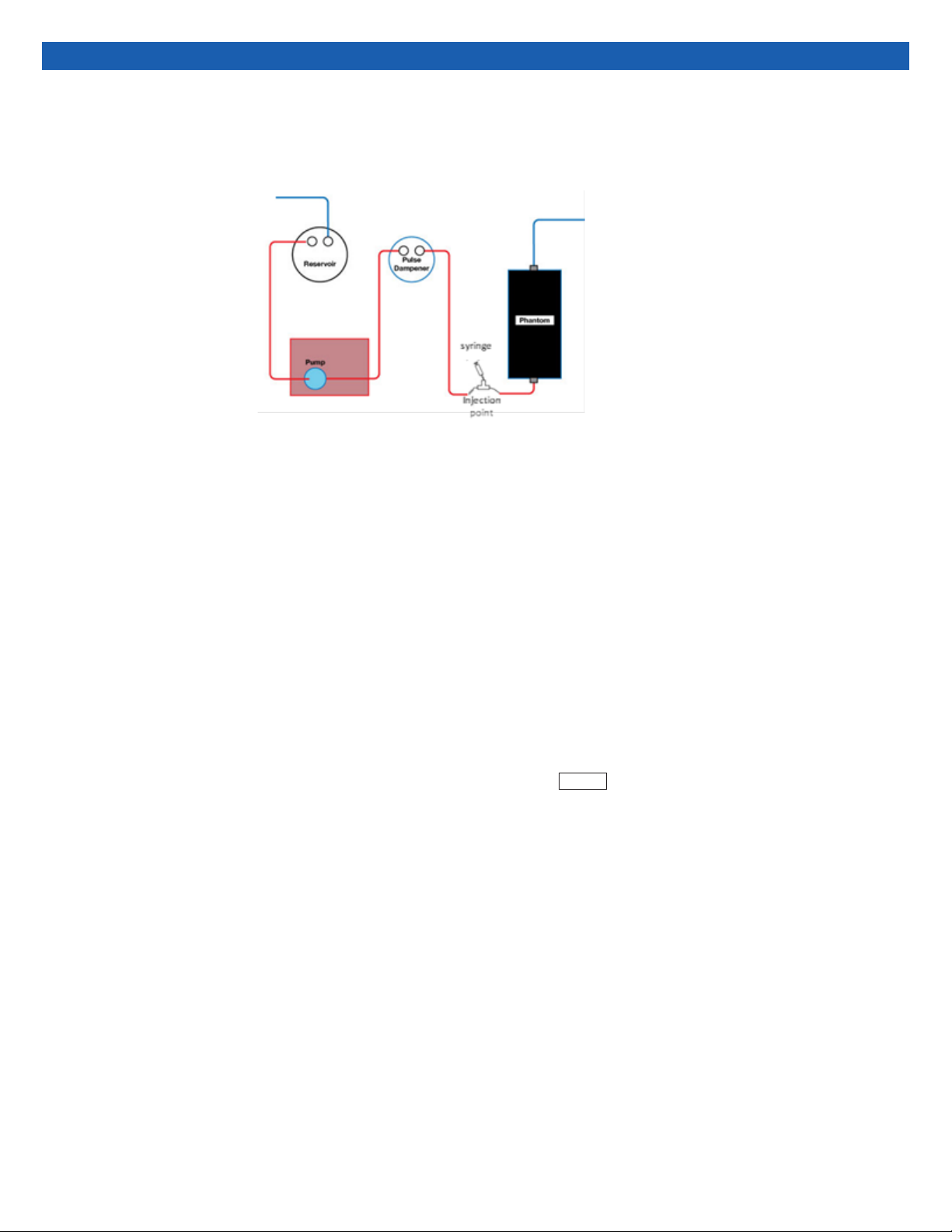
4. Construct the ow circuit
− Use the tubing pack and pulse dampener to construct a ow circuit with a Doppler phantom.
− For constant velocity ow, direct ow through the pulse dampener. (Setup 1)
− For pulsatile ow, remove the pulse dampener. (Setup 2)
5. Start the pump
− Momentarily press the ‘start/stop’ key to start the pump.
− The pumping rate can be changed by pressing the up-arrow keys, even while the pump is running. Note the pump
can make a loud noise at some ow settings. A small change in pump speed will eliminate this noise.
6. Stop the pump
− Momentarily press the ‘start/stop’ key to stop the pump.
Unt 5
or:01
OFF
9
1. Press the ‘diameter’/’setup’ key while turning on power to the pump. The display shows
2. Use the up-arrow keys to scroll through to
3. Press ‘rate’ or ‘volume’ or wait for the time out to select.
4. The display shows: where ‘n’ is the setting: ‘0’ = disabled, ‘1’ = enabled.
5. Use the up arrow to disable dispense mode. The display shows
6. Press ‘rate’ or ‘volume’ or wait for the time out to select.
The pump has a dispense mode that is useful for lling up bottles. But before programming the pump, the dispense mode must be disabled.
1. Go to http://www.syringepump.com
2. Under “Accessories”, click on “Pump Software.”
3. Scroll down to PumpTerm. Download for free.
4. Follow the installation instructions included in the download
Program Pulsitile Flow
To program pulsatile ow, you must rst download and install the PumpTerm program.
diA
disP
dis:n
dis:0
The pump is ready for programing.
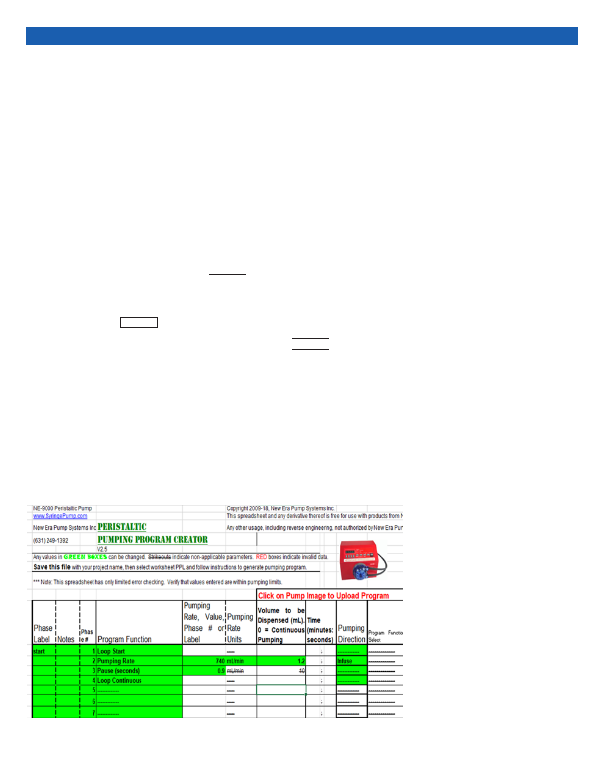
For a 60 beats-per-minute pulse, open the PPL Creator excel spreadsheet. Using the drop-down menu in each cell, set
− Phase 1 to Loop Start
− Phase 2 to Pumping Rate 740 ml/min for 1.2ml
− Phase 3 to Pause (seconds) 0.9
− Phase 4 to loop continuously.
− Leave other phases blank
The excel page will look like this:
Upload the program to the pump by
clicking on the pump picture in the Excel
le. The pump will beep twice to indicate
successful program upload.
10
Contrast Injection Setup
The model 769 can be used for contrast injection studies. See Setup 3 below. The outlet from the phantom is collected in a separate container.
The injection (not included with 769) is put between the pulse dampener and phantom.
The ow rate generated in a peristaltic pump depends on the inside diameter of the tubing used, the amount of occlusive force generated by
the pump head rollers and the pump head speed (revolutions per minute, or RPM). The control indicator for the pump is calibrated to the pump
RPM setting speed and converted to ow rate for a given tube diameter. However, the actual ow rate may vary from the value indicated if the
tubing stretches or deforms over time, causing the amount of occlusive force to change over time. Differing viscosities will also affect pumping
speed.
The pump has a built-in calibration setting, in which the pump operates in the dispense mode to deliver 250 mL of uid at a ow rate of 500 mL/
min. To calibrate the pump, you will need a graduated cylinder or similar calibrated measuring cup to verify the actual dispense volume.
NOTE: The graduated cylinder provided with the Model 769 is not calibrated & is provided for convenience. Users needing to perform calibra-
tion measurement as part of a quality process may want to obtain a calibrated cylinder.
cAlr
Calibration and Resetting
Pump calibration
1. Turn off power to the pump.
2. Press the ‘rate’ key while turning on power to the pump. The display will show:
3. Press the ‘start’ key to begin the dispense.
4. When the pump has dispensed 250 ml of uid it will stop, and the dispensed volume will be displayed with the volume units LED
blinking.
5. Use the up-arrow keys to enter the actual volume measured by the graduated cylinder.
6. Press the ‘rate’ key.
The pump uses the entered volume to recalibrate the pumping rate and dispense volume. Calibration may need to be repeated multiple times for
the best results.
Changing the tubing diameter or resetting the pump will cancel the entered calibration. The pump will use the tube diameter as the calibration
value.

11
Care and Handling
When the pump is not in use, remove the black tubing from the pump head. If the tubing is left in the pump head while the rotor is stationary, the
tubing will become stretched out. Failure to remove the tubing from the pump head will result in premature wear of the tubing, which
could aect pump calibration.
1. Disconnect the reservoir outlet from the pump and leave the tube in air.
2. Run the pump until all remaining uid is returned to the reservoir. Some uid will remain in the pulse dampener. This is by design. The
pulse dampener can be stored with uid inside. The uid will not leak out of the pulse dampener.
3. Turn off the pump. Remove the reservoir adaptor tubing from the Doppler uid. Replace the standard cap on the Doppler uid
4. Fill graduated cylinder with water and place the reservoir adapter in the cylinder. Remove the pulse dampener.
5. Re-attach reservoir outlet to the pump and circulate water through the phantom to clean any remaining Doppler uid from the circuit.
When complete, turn off the pump, disconnect the tubing from the phantom and return accessories to the pump storage drawer.
Storage conditions vary for each phantom. In general, urethane-based phantoms can be stored empty, while Zerdine-based phantoms
should remain lled with water to prevent the tube from collapsing. For more information, see the User Guide for the phantom.
4. Remove the black tubing from the circuit as described above. Place the pump head and black tubing in the pump storage drawer.
This pump is programable, so it can behave in unexpected ways if programmed incorrectly. If your pump is acting strange, resetting the pump
will clear the programs memory and return the pump to a continuous ow mode.
The pump has a built-in calibration setting, in which the pump operates in the dispense mode to deliver 250 mL of uid at a ow rate of 500 mL/
min. To calibrate the pump, you will need a graduated cylinder or similar calibrated measuring cup to verify the actual dispense volume.
Resetting the pump
Calibration and Resetting (Cont)
1. Press the right-most up arrow key while turning on power to the pump.
2. The display will show rEST
Pressing any key will clear the display.
After each use
1. Remove the pump head from the pump by turning the cassette counterclockwise
2. Remove the black tubing from between the cassette and rotor.
Doppler uid will not affect the tubes in the pumping system. However, particle agglomeration can occur if the Doppler uid remains stationary in
a tight space for too long. Particle agglomeration may cause the tubes to become clogged if the pump is not run for an extended period of time.
Purging the circuit of Doppler uid with water will ensure the tubes do not become clogged. To purge the circuit, follow the steps below:
Preparing for storage
12
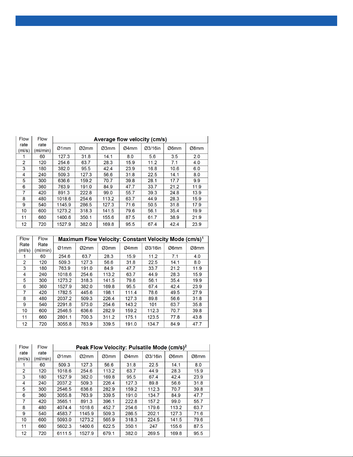
Appendix 1: Conversion of Flow
Rate to Flow Velocity
The conversion from ow rate to average ow velocity is made by dividing the ow rate by the cross-sectional area of the tubing.
For laminar ow, the ow velocity at the center of the tube is double the average ow velocity. In constant velocity mode, the maximum ow
velocity is double the average ow velocity. In pulsatile mode, the maximum ow velocity depends on the shape of the pulse prole. Assuming a
simple sine wave, the peak ow velocity will be double the maximum ow velocity in constant velocity mode.
CIRS doppler phantoms often have multiple ow tubing of different diameters by design. The following table have ow rates calculated using the
most common tubing diameters found in CIRS doppler phantoms.
Conversion Chart for Flow Velocities
1maximum ow velocity is given for laminar ow, in which the ow velocity at the center of the tube is
twice the average ow velocity.
2assumes simple sine wave pulse.

13
All standard CIRS products and accessories are warranted by CIRS
against defects in material and workmanship for a period as speci-
ed below. During the warranty period, the manufacturer will repair
or, at its option, replace, at no charge, a product containing such
defect provided it is returned, transportation prepaid, to the manu-
facturer. Products repaired in warranty will be returned transportation
prepaid.
There are no warranties, expressed or implied, including without
limitation any implied warranty of merchantability or tness, which
extend beyond the description on the face hereof. This expressed
warranty excludes coverage of, and does not provide relief for,
incidental or consequential damages of any kind or nature, includ-
ing but not limited to loss of use, loss of sales or inconvenience. The
exclusive remedy of the purchaser is limited to repair, recalibration,
or replacement of the product at manufacturer’s option.
This warranty does not apply if the product, as determined by the
manufacturer, is defective because of normal wear, accident, mis-
use, or modication.
NON-WARRANTY SERVICE
If repairs or replacement not covered by this warranty are required, a
repair estimate will be submitted for approval before proceeding with
said repair or replacement.
PRODUCT WARRANTY PERIOD
Model 769- Doppler Flow
Pump 24 Months
Warranty
RETURNS
If you are not satised with your purchase for any reason, please
contact Customer Service or your local distributor prior to returning
the product. Visit https://www.cirsinc.com/distributors/ to nd your
local distributor. Call 800-617-1177, email [email protected], or fax
an RMA request form to 757-857-0523. CIRS staff will attempt to
remedy the issue via phone or email as soon as possible. If unable
to correct the problem, a return material authorization (RMA) number
will be issued. Non-standard or “customized” products may not be
returned for refund or exchange unless such product is deemed by
CIRS not to comply with documented order specications. You must
return the product to CIRS within 30 calendar days of the issu-
ance of the RMA. All returns should be packed in the original cases
and or packaging and must include any accessories, manuals and
documentation that shipped with the product. The RMA number
must be clearly indicated on the outside of each returned pack-
age. CIRS recommends that you use a carrier that offers shipment
tracking for all returns and insure the full value of your package so
that you are completely protected if the shipment is lost or damaged
in transit. If you choose not to use a carrier that offers tracking or
insure the product, you will be responsible for any loss or damage
to the product during shipping. CIRS will not be responsible for lost
or damaged return shipments. Return freight and insurance is to be
pre-paid.
With RMA number, items may be returned to:
CIRS
Receiving
900 Asbury Ave,
Norfolk, Virginia, 23513 USA

14


16
©2016 Computerized Imaging Reference Systems, Inc. All rights
reserved.
All brand names, product names or trademarks belong to
their respective holders.
Specications subject to change without notice.
Publication: Doppler 769 UG 110920
Computerized Imaging Reference Systems, Inc. has
been certied by UL DQS Inc. to (ISO) 13485:2016.
Certicate Registration No.10000905-MP2016.
COMPUTERIZED IMAGING
REFERENCE SYSTEMS, INC.
900 Asbury Ave
Norfolk, Virginia 23513 USA
Toll Free: 800.617.1177
Tel: 757.855.2765
Fax: 757.857.0523
Email [email protected]
www.cirsinc.com
Technical Assistance
1.800.617.1177
Table of contents
Popular Water Pump manuals by other brands

WITA
WITA Delta Plus UE 65A Series TRANSLATION OF THE ORIGINAL INSTALLATION AND OPERATING INSTRUCTIONS

Anest Iwata
Anest Iwata ISP-1000 instruction manual

Rheem
Rheem Classic Plus Series manual

Aussie Pumps
Aussie Pumps Eco-Clean AB Scud Cadet Series Operator's instruction manual

North Ridge Pumps
North Ridge Pumps DM troubleshooting guide

Grundfos
Grundfos TPE 2 Series Installation and operating instructions

Edwards
Edwards STP-iXR1606 instruction manual

Bosch
Bosch Universal Pump 18V Original instructions

Grundfos
Grundfos MSS Series Installation and operating instructions

Liberty Pumps
Liberty Pumps 2LE Series installation manual

ABNOX
ABNOX Standard operating manual

Graco
Graco 210-208 Instructions and parts list


