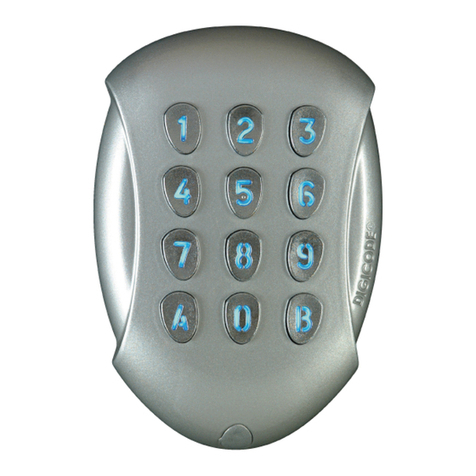
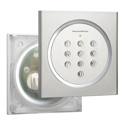
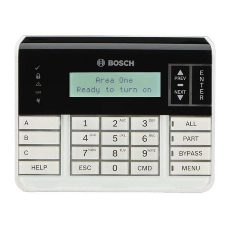
CISA 06525-75 User manual

Manuale Tastiera Digitale
art. 06525-75
IT
cisa.com
Digital Keypad Manual
item 06525-75
EN

IT
- 2 -
INTRODUZIONE
Questo manuale, che è parte integrante dell’apparecchiatura, è stato realizzato dal costruttore
per fornire le informazioni necessarie a coloro che sono autorizzati ad interagire con l’apparec-
chiatura stessa. Conservare questo manuale per tutta la durata di vita dell’apparecchiatura in un
luogo noto e facilmente accessibile. Il costruttore si riserva il diritto di apportare modiche senza
l’obbligo di fornire preventivamente alcuna comunicazione.
Per evidenziare alcune parti di testo di rilevante importanza, sono stati adottati alcuni simboli il
cui signicato viene di seguito descritto.
Importante: indica informazioni tecniche di particolare importanza da non tras-
curare.
Indicazioni per riciclo / ricaricabile.
NORME PER LA SICUREZZA
Leggere attentamente le istruzioni riportate nel manuale di installazione.
Tutti gli interventi di installazione e manutenzione che richiedono una precisa competenza tec-
nica o particolari capacità, devono essere eseguiti esclusivamente da personale qualicato, con
esperienza riconosciuta e acquisita nel settore specico di intervento.
SOMMARIO
CONTENUTO 3
DIMENSIONI 3
INSTALLAZIONE 4
Schema generale 4
Montaggio 4
Dati tecnici 5
Collegamenti 6
FUNZIONAMENTO 8
Uso tastiera 8
Programmazione Tastiera 9
PULIZIA 11
CERTIFICAZIONI 11

IT
- 3 -
CONTENUTO
n. 1 Tastiera
n. 1 Supporto a muro tastiera
n. 4 Tassello per ssaggio tastiera
n. 1 Centralina
n. 1 Supporto a muro centralina
n. 2 Tassello per ssaggio centralina
n. 1 Cavo C1
DIMENSIONI
25,55
59.3
13.5
61.7
77.6
75
5.5
19.3
61
15.7
71
48
22
47.5
48
48
61
71
48
22
15.7
37
150
139
41
127
12
4.2
150
41
1.5
76,5
59.3
13.5
61.7
77.6
75
5.5
99
83
58
59
122
88

IT
- 4 -
INSTALLAZIONE
SCHEMA GENERALE
MONTAGGIO
• Fissare le piastre di supporto della tastiera (2) e della centralina (6)
• Collegare il cavo di alimentazione (C2) e il cavo relè (C3) (vedi schema pag 6)
• Connettere il cavo tastiera (C1) dalla centralina alla tastiera (max lunghezza cavo 80 cm)
• Fissare la tastiera al relativo supporto
• Fissare la centralina al relativo supporto
Vista tastiera
3
421
C1
N° 4 Ø4
Ø10
42
42
5
C1
6
78
Vista centralina
C2
C3
N° 2 Ø4
Ø10
60
100
1 Tastiera
2 Supporto tastiera
3 Viti ssaggio tastiera
4 Tasselli ssaggio
tastiera
5 Centralina
6 Supporto centralina
7 Viti ssaggio centralina
8 Tasselli ssaggio
centralina
C1 Cavo tastiera
C2 Cavo di alimentazione
(non fornito)
C3 Cavo relè (non fornito)

IT
- 5 -
DATI TECNICI
PXR Tensione di funzionamento 12/24 VDC
Corrente assorbita <100 mA
IN Tensione apertura da remoto 5/24 V AC/DC
OUT Contatto normalmente aperto max 60 V DC
max 100 mA
Temperatura di utilizzo -20 / +80 °C
Umidità di utilizzo <90%

IT
- 6 -
COLLEGAMENTI
Congurazione generale
Importante: Il relè di uscita OUT supporta tensione max 60V e corrente 100 mA
Per comandare serrature o incontri elettrici a bobina è necessario un relè ripeti-
tore (art. 07022200)
IMPIANTO ELETTRICO
• Realizzare l’impianto elettrico conformemente alle norme vigenti.
• Effettuare l’operazione di collegamento dei cavi e successivi interventi alla centralina con
impianto elettrico non alimentato.
• Non alimentare la centralina direttamente da rete, ma attraverso l’alimentatore consigliato dal
costruttore.
• Proteggere adeguatamente l’impianto dai corto circuiti.
CISA non si assume responsabilità per i danni causati da un mancato rispetto
delle avvertenze suddette o da un utilizzo di accessori non previsti dal presente
manuale.
PWR
12/24 VDC
IN
5/24 VAC
5/24 VDC
OUT
max 60 VAC
max 100 mA
remote
OUTPUT
max 100 mA - 60 V
remote
INPUT
(optional)
12/24 VDC

IT
- 7 -
PWR
12/24 VDC
IN
5/24 VAC
5/24 VDC
OUT
max 60 VAC
max 100 mA
eFAST cable
YELLOW
BROWN
PINK
12/24 VDC
Congurazione per maniglione motorizzato CISA eFAST
12/24 VDC
Congurazione per serratuta CISA Elettrika con Booster PLUS
Maniglione motorizzato CISA eFAST
Elettrika con CISA Booster PLUS

IT
- 8 -
FUNZIONAMENTO
La tastiera digitale può funzionare in 2 diverse modalità:
Automatico: Inserendo un codice valido, l’uscita della centralina viene attivata per 500ms.
È la congurazione base di fabbrica.
Fermo a giorno: Inserendo un codice valido, l’uscita della centralina viene attivata/disattivata
alternativamente
USO TASTIERA
AZIONE SEGNALE
Apertura porta - Modalità automatica
1 Premere il tasto CISA per attivare la tastiera; Viene attivata la retroilluminazione.
2 Digitare il codice utente; Viene emesso un lampeggio verde sulla e un avviso
sonoro breve. La centralina attiva l’uscita OUT per 500 ms.
Apertura porta - Modalità automatica “Scramble Code”
1 Premere il tasto CISA per attivare la tastiera; Viene attivata la retroilluminazione.
2 Digitare il codice 0000 per attivare la modalità
“Scramble Code”.; Viene emesso un avviso sonoro lungo.
3 Inserire il codice utente preceduto da
un numero arbitrario di cifre; il numero
complessivo di cifre deve essere inferiore o
uguale a 12.
Viene emesso un lampeggio verde sulla e un avviso
sonoro breve. La centralina attiva l’uscita OUT per 500 ms.
Apertura porta - Modalità Fermo a giorno
Assicurarsi che la serratura collegata possa funzionare
in modalità fermo a giorno
1 Premere la scritta CISA per attivare la
tastiera; Viene attivata la retroilluminazione.
2 Digitare il codice 9999 per attivare la modalità
“Fermo a giorno” Viene emesso un avviso sonoro lungo.
3 Inserire il codice utente. Viene emesso un lampeggio verde sulla e un avviso
sonoro breve. La centralina attiva o disattiva l’uscita OUT.
4. Ripetere l’operazione per disattivare l’uscita
Tasto CISA
Led rosso
ERRORE
Led giallo
programmazione
Led verde
Operazione andata
a buon ne

IT
- 9 -
PROGRAMMAZIONE TASTIERA
La modalità di programmazione rimane attiva no a che l’azione dell’amministra-
tore è completata o per 15 secondi.
AZIONE SEGNALE
1. Aggiunta del codice utente
I codici che come prime cifre presentano 0000 sono riservati.
È possibile memorizzare no a 30 codici utente.
1.1. Premere la scritta CISA per attivare la tastiera; Viene attivata la retroilluminazione.
1.2. Digitare il codice Master di 8 cifre
(codice di fabbrica 12345678) Viene emesso 1 lampeggio verde sulla e un avviso
sonoro breve. Viene attivato il LED giallo di programmazione.
1.3. Premere il tasto 1; Viene emesso 1 lampeggio verde sulla e un avviso
sonoro breve.
1.4. Inserire il codice utente (da 4 a 8 cifre); Viene emesso 1 lampeggio verde sulla e 1 avviso
sonoro lungo
1.5. Re-Inserire il codice utente. Vengono emessi 2 lampeggi verdi sulla e 2 avvisi sonori
brevi a conclusione dell’operazione
2. Cancellazione del codice utente
2.1. Premere la scritta CISA per attivare la tastiera; Viene attivata la retroilluminazione.
2.2. Digitare il codice Master di 8 cifre; Viene emesso 1 lampeggio verde sulla e un avviso
sonoro breve. Viene attivato il LED giallo di programmazione.
2.3. Premere il tasto 2; Viene emesso 1 lampeggio verde sulla e un avviso
sonoro breve.
2.4. Inserire il codice utente; Se il codice inserito è valido, viene emesso 1 lampeggio
verde sulla e 1 avviso sonoro lungo
2.5. Re-Inserire il codice utente. Vengono emessi 2 lampeggi verdi sulla e 2 avvisi sonori
brevi a conclusione dell’operazione
3. Cancellazione di tutti i codici utente
3.1. Premere la scritta CISA per attivare la tastiera; Viene attivata la retroilluminazione.
3.2. Digitare il codice Master di 8 cifre; Viene emesso 1 avviso sonori breve e 1 lampeggi verde sulla
.
3.3. Premere il tasto 3; Viene emesso 1 lampeggio verde sulla e un avviso
sonoro breve.
3.4. Re-Inserire il codice Master; Vengono emessi 2 lampeggi verdi sulla e 2 avvisi sonori
brevi a conclusione dell’operazione

IT
- 10 -
AZIONE SEGNALE
4. Cambio della lunghezza del codice utente
È possibile cambiare la lunghezza del codice utente solo se non ci sono codici registrati. Nel caso siano già
presenti codici registrati, ripetere la procedura del punto 3. “Cancellazione di tutti i codici utente”.
4.1. Premere la scritta CISA per attivare la tastiera; Viene attivata la retroilluminazione.
4.2. Digitare il codice Master di 8 cifre; Viene emesso un avviso sonori breve e un lampeggio verde
sulla . Viene attivato il LED giallo di programmazione
4.3. Premere il tasto 4; Viene emesso un lampeggio verde sulla e un avviso
sonoro breve.
4.4. Digitale il numero di cifre desiderate
(da 4 a 8). Vengono emessi 2 lampeggi verdi sulla e 2 avvisi sonori
brevi a conclusione dell’operazione.
5. Cambio del codice Master
5.1. Premere la scritta CISA per attivare la tastiera; Viene attivata la retroilluminazione.
5.2. Digitare il codice Master di 8 cifre; Viene emesso un avviso sonori breve e un lampeggio verde
sulla . Viene attivato il LED giallo di programmazione
5.3. Premere il tasto 5; Viene emesso un lampeggio verde sulla e un avviso
sonoro breve.
5.4. Inserire il nuovo codice Master; Viene emesso un lampeggio verde sulla e un avviso
sonoro lungo.
5.5. Re-Inserire il codice Master. Vengono emessi 2 lampeggi verdi sulla e 2 avvisi sonori
brevi a conclusione dell’operazione.
6. Inibizione/abilitazione del Contatto Remoto
6.1. Premere la scritta CISA per attivare la tastiera; Viene attivata la retroilluminazione.
6.2. Digitare il codice Master di 8 cifre; Viene emesso un avviso sonori breve e un lampeggio verde
sulla . Viene attivato il LED giallo di programmazione
6.3. Premere il tasto 6. Vengono emessi 2 lampeggi verdi sulla e 2 avvisi sonori
brevi a conclusione dell’operazione.
7. Selezionare la modalità Automatica
7.1. Premere la scritta CISA per attivare la tastiera; Viene attivata la retroilluminazione.
7.2. Digitare il codice Master di 8 cifre; Viene emesso un avviso sonori breve e un lampeggio verde
sulla . Viene attivato il LED giallo di programmazione
7.3. Premere il tasto 7. Vengono emessi 2 lampeggi verdi sulla e 2 avvisi sonori
brevi a conclusione dell’operazione.
8. Cambio del codice Fermo a giorno
8.1. Premere la scritta CISA per attivare la tastiera; Viene attivata la retroilluminazione.
8.2. Digitare il codice Master di 8 cifre; Viene emesso un avviso sonori breve e un lampeggio verde
sulla . Viene attivato il LED giallo di programmazione
8.3. Premere il tasto 8. Viene emesso un lampeggio verde sulla e un avviso
sonoro breve.
8.4. Inserire il nuovo codice Fermo a giorno; Viene emesso un lampeggio verde sulla e un avviso
sonoro lungo.
8.5. Re-Inserire il codice Fermo a giorno. Vengono emessi 2 lampeggi verdi sulla e 2 avvisi sonori
brevi a conclusione dell’operazione.

IT
- 11 -
PULIZIA
Non utilizzare solventi chimici per la pulizia della tastiera.
CERTIFICAZIONI
Il prodotto è conforme alle Direttive Europee 2011/65/UE per la restrizione delle sostanze perico-
lose e alla 2014/30/06 per la compatibilità elettromagnetica.
I prodotti qui evidenziati sono dotati di tutte le caratteristiche indicate nella descrizione tecnica dei
cataloghi CISA S.p.A. e sono consigliati solamente per gli scopi ivi precisati.
La società CISA non garantisce nessuna prestazione o caratteristica tecnica che non sia espres-
samente indicata. Per particolari esigenze di sicurezza si invita l’utente a rivolgersi al rivenditore
o installatore di questi prodotti o direttamente alla CISA, i quali potranno meglio consigliare il
modello più appropriato alle speciche esigenze del Cliente.
Per le condizioni di vendita fare riferimento al listino CISA in vigore.
AZIONE SEGNALE
9. Selezionare la modalità Fermo a giorno
9.1. Premere la scritta CISA per attivare la tastiera; Viene emesso un avviso sonori breve e un lampeggio verde
sulla . Viene attivato il LED giallo di programmazione
9.2. Digitare il codice Master di 8 cifre; Viene emesso un lampeggio verde sulla e un avviso
sonoro breve.
9.3. Premere il tasto 9. Vengono emessi 2 lampeggi verdi sulla e 2 avvisi sonori
brevi a conclusione dell’operazione.
10. Congurazione del costruttore (Factory Setup)
10.1. Premere la scritta CISA per attivare la tastiera; Viene attivata la retroilluminazione.
10.2. Digitare il codice Master di 8 cifre; Viene emesso un avviso sonori breve e un lampeggio verde
sulla . Viene attivato il LED giallo di programmazione
10.3. Premere il tasto 0; Viene emesso un lampeggio verde sulla e un avviso
sonoro breve.
10.4. Re-inserire il codice Master. Vengono emessi 2 lampeggi verdi sulla e 2 avvisi sonori
brevi a conclusione dell’operazione.

EN
- 12 -
INTRODUCTION
This manual is an integral part of the product and has been compiled by the manufacturer to
provide everyone authorised to interact with it with the information they may need. Keep this
manual in an easily accessible place for the working life of the product and make sure everyone
knows where it is. The manufacturer reserves the right to make changes to this manual without
prior notice.
Different symbols are used to indicate parts of the manual of particular importance and their
meaning is explained below.
Important: indicates extremely important technical information which must not
be ignored.
Instructions about recycling / recharging.
SAFETY REGULATIONS
Read the instructions in the installation manual carefully.
All installation and maintenance operations which require precise technical expertise or particular
skills must be carried out exclusively by qualied personnel with the relevant qualications and
experience in the sector.
CONTENTS
KEYPAD PARTS 13
DIMENSIONS 13
INSTALLATION 14
General overview 14
Installation 14
Technical data 15
Wiring 16
OPERATION 18
How to use the keypad 18
How to programme the keypad 19
CLEANING 21
CERTIFICATIONS 21

EN
- 13 -
CONTENTS
1 Keypad
1 Keypad wall support plate
4 Keypad screws and plugs
1 Control unit
1 Control unit wall support plate
2 Control unit screws and plugs
1 Cable C1
DIMENSIONS
25,55
59.3
13.5
61.7
77.6
75
5.5
19.3
61
15.7
71
48
22
47.5
48
48
61
71
48
22
15.7
37
150
139
41
127
12
4.2
150
41
1.5
76,5
59.3
13.5
61.7
77.6
75
5.5
99
83
58
59
122
88

EN
- 14 -
INSTALLATION
GENERAL OVERVIEW
INSTALLATION
• Fix the support plates of the keypad (2) and the control unit (6)
• Connect the power supply cable (C2) and relay cable (C3) (see diagram on page 16)
• Connect the keypad cable (C1) from the control unit to the keypad (cable length 80 cm)
• Fix the keypad to its support
• Fix the control unit to its support
Keypad view
3
421
C1
N° 4 Ø4
Ø10
42
42
5
C1
6
78
Control unit view
C2
C3
N° 2 Ø4
Ø10
60
100
1 Keypad
2 Keypad support plate
3 Keypad xing screws
4 Keypad plugs
5 Control unit
6 Control unit support plate
7 Control unit xing screws
8 Control unit plugs
C1 Keypad cable
C2 Power supply cable
(not supplied)
C3 Relay cable (not supplied)

EN
- 15 -
TECHNICAL DATA
PWR Opeating voltage 12/24 VDC
Corrente assorbita <100 mA
IN Remote Input voltage 5/24 V AC/DC
OUT Remote output normaly open max 60 V DC
max 100 mA
Operating temperature -20 / +80 °C
Operating temperature <90%

EN
- 16 -
WIRING
General conguration
PWR
12/24 VDC
IN
5/24 VAC
5/24 VDC
OUT
max 60 VAC
max 100 mA
remote
OUTPUT
max 100 mA - 60 V
remote
INPUT
(optional)
12/24 VDC
Important: The OUT relay can withstand a maximum voltage of 60V and 100 mA
current
A repeater relay (item 07022200) is needed to control locks or electric strike coils
ELECTRIC SYSTEM
• The electric system must comply with regulations in force.
• Always disconnect the electric system from the mains when connecting the cables or
performing any later work on the control unit.
• Do not power the control unit directly from the mains but use a power supply recommended
by the manufacturer.
• Protect the system appropriately against short circuits.
CISA declines all responsibility for damage resulting from the failure to observe the
above warnings or when accessories are not used as described in this manual.

EN
- 17 -
PWR
12/24 VDC
IN
5/24 VAC
5/24 VDC
OUT
max 60 VAC
max 100 mA
eFAST cable
YELLOW
BROWN
PINK
12/24 VDC
Conguration for eFAST motorised panic exit device
12/24 VDC
Conguration for CISA Elettrika lock with Booster PLUS
CISA eFAST motorised panic exit device
CISA Elettrika with Booster PLUS

EN
- 18 -
OPERATION
The digital keypad has 2 different operating modes:
Automatic: When a valid code is entered, control unit output is activated for 500ms.
This is the factory setup.
Hold open: When a valid code is entered, control unit output is automatically activated/
deactivated.
HOW TO USE THE KEYPAD
PROCEDURE SIGNAL
To open the door - Automatic mode
1 Press the CISA key to activate the keypad; It is automatically backlit.
2 Enter the user code; The symbol will ash green once and a short beep will
be heard. The control unit activates output for 500 ms.
To open the door - Automatic mode “Scramble Code”
1 Press the CISA key to activate the keypad; It is automatically backlit.
2 Enter the code 0000 to activate the “Scramble
Code” mode; A long beep will be heard.
3 Enter the user code preceded by an arbitrary
number of gures; the total number of gures
must be 12 or less.
The symbol will ash green once and a short beep will
be heard. The control unit activates output for 500 ms.
To open the door - Passage mode
Make sure the connected lock can operate in hold open mode
1 Press the CISA key to activate the keypad; It is automatically backlit.
2 Enter the code 9999 to activate the “Passage
Code” mode; A long beep will be heard.
3 Enter the user code; The symbol will ash green once and a short beep
will be heard. The control unit activates or deactivates the
OUTPUT.
4 Repeat the procedure to deactivate output
CISA key
Red LED
ERROR
Yellow LED
Programming
Green LED
Operation successfully
completed

EN
- 19 -
HOW TO PROGRAMME THE KEYPAD
Programming mode remains active until the administrator has completed the
procedure or for 15 seconds
PROCEDURE SIGNAL
1. Adding a user code
Codes preceded by 0000 are not allowed.
Up to 30 user codes can be stored.
1.1. Press the CISA key to activate the keypad; It is automatically backlit.
1.2. Enter the 8-digit Master Code;
(Factory code 12345678) The symbol will ash green once and a short beep will
be heard. The yellow programming LED will come on.
1.3. Press 1; The symbol will ash green once and a short beep will
be heard.
1.4. Enter the user code (from 4 to 8 digits); The symbol will ash green once and a short beep will be
heard.
1.5. Re-enter the user code. The symbol will ash green twice and two short beeps
will be heard if the operation is successfully completed
2. Deleting the user code
2.1. Press the CISA key to activate the keypad; It is automatically backlit.
2.2. Enter the 8-digit Master Code; The symbol will ash green once and a short beep will
be heard. The yellow programming LED will come on.
2.3. Press 2; The symbol will ash green once and a short beep will
be heard.
2.4. Enter the user code; If the code is valid, the symbol will ash green once and
and a long beep will be heard.
2.5. Re-enter the user code. The symbol will ash green twice and two short beeps
will be heard if the operation is successfully completed
3. Deleting all user codes
3.1. Press the CISA key to activate the keypad; It is automatically backlit.
3.2. Enter the 8-digit Master Code; A short beep will be heard and the symbol will ash
green once.
3.3. Press 3; The symbol will ash green once and a short beep will
be heard.
3.4. Re-enter the Master Code; The symbol will ash green twice and two short beeps
will be heard if the operation is successfully completed

EN
- 20 -
PROCEDURE SIGNAL
4 Changing the length of the user code
It is possible to change the length of the user code only if no codes have been set. If codes have already
been set, repeat the procedure described in point 3. “Deleting all user codes”.
4.1. Press the CISA key to activate the keypad; It is automatically backlit.
4.2. Enter the 8-digit Master Code; A short beep will be heard and the symbol will ash
green once. The yellow programming LED will come on.
4.3. Press 4; The symbol will ash green once and a short beep will
be heard.
4.4. Enter the desired numbers (from 4 to 8). The symbol will ash green twice and two short beeps
will be heard if the operation is successfully completed.
5 Changing the Master Code
5.1. Press the CISA key to activate the keypad; It is automatically backlit.
5.2. Enter the 8-digit Master Code; A short beep will be heard and the symbol will ash
green once. The yellow programming LED will come on.
5.3. Press 5; The symbol will ash green once and a short beep will
be heard.
5.4. Enter the new Master Code; The symbol will ash green once and a long beep will
be heard.
5.5. Re-enter the Master Code; The symbol will ash green twice and two short beeps
will be heard if the operation is successfully completed.
6 Disabling/enabling the remote control
6.1. Press the CISA key to activate the keypad; It is automatically backlit.
6.2. Enter the 8-digit Master Code; A short beep will be heard and the symbol will ash
green once. The yellow programming LED will come on.
6.3. Press 6. The symbol will ash green twice and two short beeps
will be heard if the operation is successfully completed.
7 Selecting automatic mode
7.1. Press the CISA key to activate the keypad; It is automatically backlit.
7.2. Enter the 8-digit Master Code; A short beep will be heard and the symbol will ash
green once. The yellow programming LED will come on.
7.3. Press 7. The symbol will ash green twice and two short beeps
will be heard if the operation is successfully completed.
8 Changing the Passage code
8.1. Press the CISA key to activate the keypad; It is automatically backlit.
8.2. Enter the 8-digit Master Code; A short beep will be heard and the symbol will ash
green once. The yellow programming LED will come on.
8.3. Press 8. The symbol will ash green once and a short beep will
be heard.
8.4. Enter the new Passage Code; The symbol will ash green once and a long beep will
be heard.
8.5. Re-enter the Passage Code; The symbol will ash green twice and two short beeps
will be heard if the operation is successfully completed.
Table of contents
Languages:
